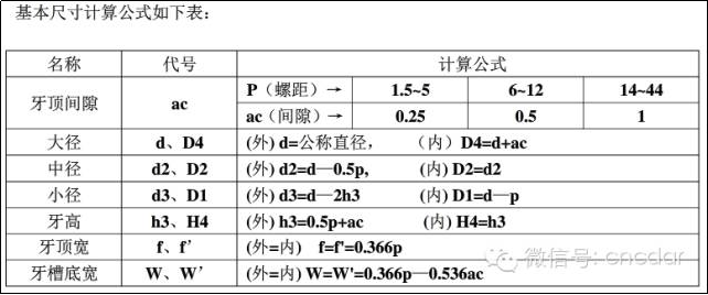

1. Trapezoidal thread size
Calculation: (Calculation table based on basic dimensions)
Unilateral tooth height: h3=0.5p+ac=0.5×6+0.5=3.5 mm
Place the trapezoidal thread at the small diameter: d3=d—2h3=36—2×3.5=29mm
Upper width: f=f’=0.366×P=0.366×6=2.196≈2.2
Honeycomb base width (sharpening width): W=W’=0.366×P—0.536×ac=1.928≈1.93 mm
Therefore, let the width of the sword be 2mm (a few inches larger than 1.93 due to wear)
If the material is hard, such as steel, etc., two knives are usually required;
1. ① The first tool is a rough turning tool. (Grind the tool coarsely) To set the tool normally, the key is to leave a margin for the fine turning tool to be repaired.
② The second tool is a precision turning tool (the tool needs to be precisely ground, 0.1 too large, due to wear, and it cannot be sized, and it has a clearance margin “ac “). The tool should be adjusted normally). (Z0 position), it is essential to adjust the “Z” offset (-0.15~-0.2mm) in the wear column at the same time, so that both sides of the knife can be polished during finishing .
2. ① Generally, if you have higher requirements, just use G92 to follow the size.
② Pay attention to higher requirements. First of all, you should separate the coarse and fine turning, and pay attention to the cutting margin, for example, leave a margin of 0.1 outside the car and inside the bore. , (because there are burrs), then use a turning tool or boring tool to cut it to the right size, and finally use a trapezoidal wire cutter to smooth it again, so that once The trapezoidal thread placed, it is more pleasant to the touch and appearance.
As shown below

Macro-program layered processing of large-pitch trapezoidal threads
1. Parameter table: variables and meanings used in the macro program[2, 3]are presented in Table 1.
Table 1 Variables and their meanings

Figure 1 External trapezoidal thread
Trapezoidal thread fittings

2. Analysis of trapezoidal thread turning process
There are many ways to process trapezoidal threads: straight feed method, oblique feed method, left and right cutting method, straight groove turning method, layered method, etc. Since the trapezoidal thread has a larger pitch and tooth profile than the triangular thread, and it has high precision, and the surface roughness value on both sides of the tooth profile is smaller, the The result is that when rotating the trapezoidal thread, the cutting tool is deep, the cutting speed is fast, and the cutting margin is large. Using macro programs for layering can effectively resolve problems that arise.
The layered method for turning trapezoidal threads is actually a complete application of the simple method and the left-right cutting method. When turning trapezoidal threads with extremely large pitches, the “layer method” generally does not cut the trapezoidal groove in one go, but divides the groove into several layers, and the depth of each layer is determined according to the real situation. Converting it to several shallower trapezoidal grooves for cutting can reduce the difficulty of turning. The cutting of each layer adopts the left and right alternating rotation method. The amount of cutting at the back is very small. The tool only needs to cut along the left and right profile lines. The trapezoidal wire cutter always has only one side edge. participating in the cut (Figure 2), thus making chip removal more efficient. Smoothly, the strength and heat of the tool tip have been improved, so that higher quality trapezoidal threads can be processed, and the procedure is easy to master. short and easy to use.
Figure 2 Layered cutting method

2. Size calculation (omitted)
3. Program: Taking the FanucOi mate TC system as an example, the trapezoidal thread processing program shown in Figure 1 is as follows:
O0001 (grooving, etc. omitted)
T0101 M03 S300; Replace with trapezoidal wire cutter, spindle speed 300 rpm.
G00 X38 Z5; walk quickly to the starting point;
M08; activate cooling
#101=36; Nominal thread diameter
#102=0; Initial value of the amount borrowed on the right
#103=-1.876; Initial value of the amount borrowed on the left (tg15×3.5×2 or 0.938×2)
#104=0.2; The depth of each knife attack, initial value
N1 IF[#101 LT 29] GOTO2; treatment until the end of the small cycle
G00Z[5+#102]; Quickly walk to the right to deal with the starting point
G92X[#101] Z—30 F6; Treat a cut on the right side.
G00Z[5+#103];(walk quickly to the left processing starting point Z5)+(initial value of left tool borrowing amount -1.876)
G92X[#101] Z—30 F6; deal with a knife left.
#101=#101-#104; Change the thread processing diameter (the outer circle of the shaft should become smaller and smaller, so use the “-” value)
#102=#102-0.134×#104; Calculate the loan amount on the right side after changing the cutting depth (tg15∕2=0.134)
#103=#103+0.134×#104; Calculate the remaining loan amount after changing the cutting depth (tg15∕2=0.134)
IF[#101 LT 34] THEN#104=0.15; When below 34, the depth of each knife attack is 0.15;
IF[#101 LT 32] THEN#104=0.1; When less than 32, the depth of each knife attack is 0.1;
IF[#101 LT 30] THEN#104=0.05; When less than 32, the depth of each knife attack is 0.05;
GO TO 1;
N2 G92 X29 Z-30 F6; finishing two cuts at the lower diameter.
G92 X29 Z-30 F6;
GOO X100 Z200 M09; tool holder retracts quickly, turns off cooling
M05;
M30; End of program
Internal trapezoidal thread (Tr36×6) Figure 2 Internal trapezoidal thread (for reference)
Size calculation:
Find the small diameter: D1=dp=36-6=30
Find the large diameter: D4=d+ac=36+0.5=36.5
4. Program: Taking Fanuc Oi mateTC system as an example, the trapezoidal thread processing program shown in Figure 1 is as follows:
O0002;(boring, etc. omitted)
T0101 M03 S300; Replace with trapezoidal wire cutter, spindle speed 300 rpm.
G00 X27 Z5; walk quickly to the starting point;
M08; activate cooling
#101=30; Nominal thread diameter
#102=0; Initial value of the amount borrowed on the right
#103=-1.876; Initial value of the amount borrowed on the left (tg15×3.5×2 or 0.938×2)
#104=0.2; The depth of each knife attack, initial value
N1 IF[#101 GT 36.5] GOTO2; treatment until the end of the large cycle
G00Z[5+#102];Walk quickly to the starting point on the right (Z5 is the starting point)
G92X[#101] Z-30 F6; A cut on the right side
G00Z[5+#103];(Walk quickly to the left processing starting point Z5)+(Initial value of left tool borrowing amount -1.876)
G92X[#101] Z-30 F6; Deal with a knife left.
#101=#101+#104; Change the thread processing diameter (the inner hole should be larger and larger, so use the “+” value)
#102=#102-0.134×#104; Calculate the loan amount on the right side after changing the cutting depth (tg15∕2=0.134)
#103=#103+0.134×#104; Calculate the loan amount on the left side after changing the cutting depth (tg15∕2=0.134)
IF[#101GT 32] THEN #104=0.15 When greater than 34, the depth of each knife attack is 0.15;
IF[#101GT 34] THEN #104=0.1 When greater than 34, the depth of each knife attack is 0.1;
IF[#101GT 36] THEN #104=0.05 When greater than 34, the depth of each knife attack is 0.05;
GO TO 1;
N2 G92 X36.5 Z-30 F6; processes two knives with a smaller diameter.
G92 X36.5 Z-30 F6;
G00 X100 Z200 M09; The tool holder returns quickly and cuts off the cooling
M05; The spindle stops
M30; End of program
Note: ① Compare the two macro programs: the difference between shaft and hole (bold red)
② When finishing with 45 steel, S300 cannot be used too quickly.
③There is a famous phenomenon during trial processing, such as the length of the wire is 30mm; when the wire is processed to about 25mm long and the tail is removed, it still moves 4-5mm in the negative Z direction before returning to the positioning point; I don’t know why and I don’t understand. At present, the processing can only be solved by lengthening the width of the undercut groove.
Daguang focuses on providing solutions such as precision CNC machining services (3-axis, 4-axis, 5-axis machining), CNC milling, 3D printing and rapid prototyping services.


