When programming a CNC, the programmer must determine the amount of cut for each process and write it into the program as instructions. Cutting usage includes cutting speed, reverse cutting amount and feed speed, etc. For different processing methods, different cutting quantities should be selected.
1. Principle of selection of cutting amount
When drafting, the focus is usually on improving productivity, but saving and processing costs must also be considered; during semi-finishing and finishing, cutting efficiency, economy and processing costs should be considered while ensuring processing quality. The specific values should be determined based on the machine tool manual, cutting operation manual and experience.
Starting from the durability of the tool, the order of selecting the cutting amount is as follows: first determine the back cutting amount, then determine the feed amount, and finally determine the cutting speed.
2. Determining the amount of knife on the back
The amount of back cut is determined by the rigidity of the machine tool, workpiece and tool. If rigidity allows, the amount of back cut should be as much as possible equal to the machining allowance of the part. This can reduce the number of back cuts. tool passes and improve production efficiency.[Groupe de l’industrie des machines, rejoignez-nous maintenant]
Principles of determining the amount of knife on the back:
(1) When the surface roughness value of the workpiece needs to be Ra12.5μm~25μm, if the machining allowance of CNC machining is less than 5mm~6mm, rough machining feed can meet the requirements. However, when the margin is large, the rigidity of the processing system is poor or the power of the machine tool is insufficient, it can be carried out in several feeds.
(2) When the surface roughness value of the workpiece needs to be Ra3.2μm~12.5μm, it can be divided into two stages: roughing and semi-finishing. The selection of the back cutting amount when rough machining is the same as before. Leave a margin of 0.5mm to 1.0mm after rough machining and remove it during semi-finishing.
(3) When the surface roughness value of the workpiece needs to be Ra0.8μm~3.2μm, it can be divided into three stages: roughing, semi-finishing and finishing. The amount of back cutting during semi-finishing is 1.5mm to 2mm. During finishing, the back cutting quantity should be 0.3mm to 0.5mm.
3. Determination of the quantity of food
The feed quantity is mainly based on the requirements of machining accuracy and surface roughness of the workpiece as well as the selection of tool and workpiece material. The maximum feed is limited by the rigidity of the machine tool and the performance of the feed system.
Principles of determining the feed rate:
1) When the quality requirements of the workpiece can be guaranteed, in order to improve production efficiency, a higher feed speed can be selected. Usually selected in the range of 100-200 m/min.
2) When cutting, deep hole processing or processing with high speed steel tools, it is advisable to choose a lower feed speed, generally between 20-50m/min.
3) When the requirements for machining accuracy and surface roughness are high, the feed speed should be selected smaller, generally between 20-50m/min.
4) When the tool is in idle stroke, especially when “returning to zero” for a long distance, you can select the maximum feed speed set by the CNC system of the machine tool.
4. Determination of spindle speed
The spindle speed should be selected based on the allowable cutting speed and the diameter of the workpiece (or tool). The calculation formula is:
n=1000v/πD
v—-cutting speed, the unit is m/min, determined by the durability of the tool;
n—Spindle speed, the unit is r/min;
D—-Part diameter or tool diameter, the unit is mm.
The calculated spindle speed n should ultimately be selected based on the machine tool manual or a speed close to the machine tool.
In short, the specific value of cutting quantity should be determined by analogy according to the performance of the machine tool, relevant manuals and actual experience. At the same time, the spindle speed, cutting depth and feed speed can adapt to each other to form the optimal cutting amount.
Reference formula:
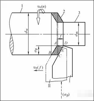
1) Back cutting quantity (cutting depth) ap
The vertical distance between the machined surface of the workpiece and the surface to be machined is called the back cut quantity. The amount of back engagement is the amount of tool engagement measured through the base point of the cutting edge and perpendicular to the work plane. This is the depth of the turning tool cutting the workpiece during each feed, so it is also called depth of cut. . According to this definition, when the outer circle is rotated longitudinally, the amount of cut on the back can be calculated according to the following formula:
ap = ( dw — dm ) /2
In the formula, ap——the amount of knife on the back (mm);
dw – diameter of the workpiece surface (mm);
dm – diameter of the machined surface of the part (mm).
Example 1: We know that the diameter of the surface of the part to be treated is Φ95 mm; Now the machine is fed up to a diameter of Φ90mm at one time, and the amount of backcut is found.
Size:ap = (dw — dm ) /2= (95 —90) /2=2.5 mm
2) Quantity of food f
The relative displacement of the tool and workpiece in the direction of feed movement for each revolution of the workpiece or tool.
According to different feeding directions, it is divided into longitudinal feed quantity and transverse feed quantity. The longitudinal feed amount refers to the feed amount along the direction of the guide rail of the lathe bed, and the transverse feed amount refers to the direction perpendicular to the guide rail of the lathe bed. guide rail of the lathe bed.
(Note) The feed rate vf refers to the instantaneous speed of the feed movement of the selected point on the cutting edge relative to the workpiece.
vf=fn
where vf——feed rate (mm/s);
n——Spindle speed (r/s);
f——feed amount (mm/s).
3) Cutting speed vc
The instantaneous speed of the main movement of a selected point on the cutting edge relative to the workpiece. The calculation formula is as follows
vc=(πdwn)/1000
In the formula, vc——cutting speed (m/min);
dw – diameter of the workpiece surface (mm);
n——Rotation speed of the part (r/min).
The calculation should be based on the maximum cutting speed. For example, when turning, the calculation should be based on the diameter of the surface to be machined, because this is where the speed is highest and tool wear is fastest.
Example 2: Turning the outer circle of a workpiece with a diameter of Φ60 mm, the selected lathe spindle speed is 600 rpm, find vc.
Solution: vc=(π dwn)/1000 = 3.14x60x600/1000 = 113 m/min
In actual production, the part diameter is often known. The cutting speed is selected based on factors such as workpiece material, tool material and processing requirements. The cutting speed is then converted to the spindle speed of the lathe in order to adjust the speed. round. We obtain the following formula:
n=(1000v c)/ πdw
Example 3: Turning the outer circle of the Φ260 mm pulley on the CA6140 horizontal lathe, select vc as 90 m/min and find n.
Solution: n=(1000v c)/ π dw=(1000×90)/ (3.14×260) =110r/min
After calculating the spindle speed of the lathe, a value close to the nameplate should be selected, i.e. n = 100 rpm should be selected as the actual speed of the lathe.
3. Summary:
cutting quantity
1. Back knife quantity ap (mm) ap= (dw – dm) / 2 (mm)
2. Feed quantity f(mm/r)
3. Cutting speed vc(m/min) Vc=∏dn/1000(m/min)
n=1000vc/∏d(r/min)
Daguang focuses on providing solutions such as precision CNC machining services (3-axis, 4-axis, 5-axis machining), CNC milling, 3D printing and rapid prototyping services.


