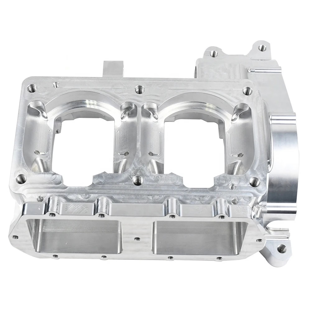
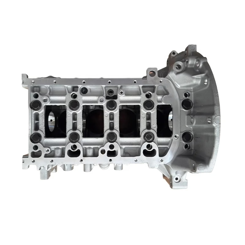
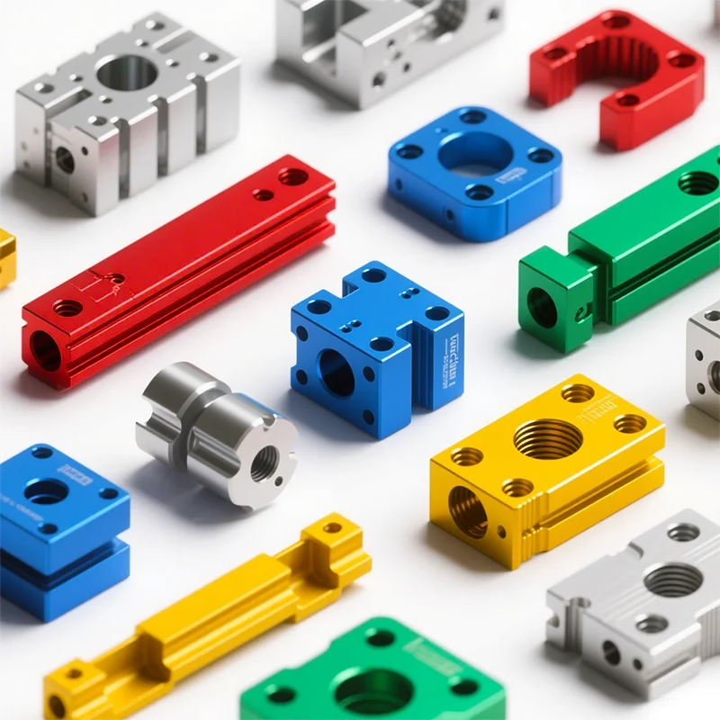
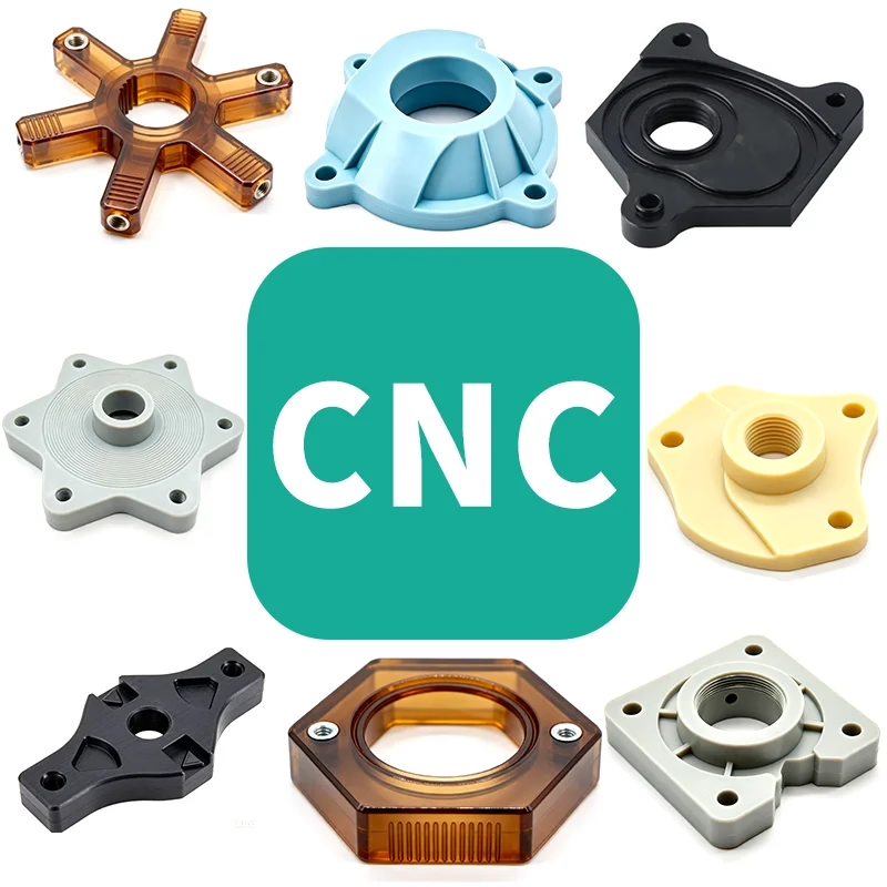
In mold factories, CNC machining centers are mainly used to process key mold parts such as mold cores and inserts, as well as copper pins. The quality of the mold core and inserts directly determines the quality of the part forming the mold. Tonggong’s processing quality directly limits the impact of EDM processing. The key to ensuring quality in CNC machining lies in preparation before processing. For this position, in addition to having rich processing experience and mold knowledge, you also need to pay attention to good communication at work, especially with the production team and colleagues. .
▌CNC machining process
1) Read the drawings and program sheets
2) Transfer the corresponding program to the machine tool
3) Check the program header, cutting parameters, etc.
4) Determination of process dimensions and tolerances on the part
5) Reasonable tightening of parts
6) Precise alignment of parts
7) Accurate establishment of room coordinates
8) Reasonable selection of tools and cutting parameters
9) Reasonable tool tightening
10) Safe trial cutting method
11) Observation of the treatment process
12) Adjustment of cutting parameters
13) Problems during processing and timely feedback from corresponding personnel
14) Part quality inspection after processing
▌ Precautions before treatment
1) For new molds, the processing drawings must meet the requirements and the data must be clear; Processing drawings for new molds must be signed by the supervisor and all columns of the processing drawings must be completed.
2) The part bears the quality department qualification mark.
3) After receiving the program sheet, check whether the reference position of the part is consistent with the reference position of the drawing.
4) Read each requirement clearly on the program sheet and confirm whether the program conforms to the requirements on the drawings. If there are any problems, you must work with the programmer and production team to resolve the problem.
5) Based on the material and size of the workpiece, judge the rationality of the programmer’s tool selection for roughing or smooth cutting programs. If the application of the tool proves unreasonable, the programmer must be immediately informed to make corresponding changes. improve processing efficiency and processing precision of parts.
▌Precautions for tightening parts
1) When tightening the workpiece, pay attention to the code position and appropriate extension length of nuts and bolts on the pressure plate. Also, when locking the corners, the screws should not be pushed down.
2) Tonggong is usually processed for lock plates. Before getting on the machine, the number of cutting materials on the program sheet should be checked to ensure compliance. At the same time, check whether the closing screws are tight.
3) In case several pieces of copper are collected on one board, check whether the direction is correct and whether there is any interference during the processing of each copper material.
4) Tighten the workpiece according to the shape of the program sheet and the size data of the workpiece. It should be noted that the part size data is written as if it matches, pay attention to the direction that comes out and how to rotate the X. and Y axes.
5) When clamping the workpiece, it is necessary to check whether the size of the workpiece meets the size requirements of the program sheet. If there is a spare part drawing, it is necessary to check whether the program sheet size and size. of the drawing of the spare parts are the same.
6) The workbench and bottom of the workpiece must be cleaned before placing the workpiece on the machine. Use a sharpening stone to remove burrs and damaged areas on the machine table and workpiece surface.
7) When coding the encoder, make sure that the encoder will not be injured by a knife, and communicate with the programmer if necessary. At the same time, if the bottom pad is square, the yard must be aligned with the square position of the pad to achieve balanced force.
8) When using a vise for clamping, you should know the processing depth of the tool to prevent the clamped position from being too long or too short.
9) The screws should be placed in the T-shaped block and only part of the threads should be used. If the screws are to be connected, half of the joint threads should be used for the upper and lower threads. The nut on the pressure plate should be fully used and only a few threads should be used.
10) When setting the Z depth number, you should clearly see the position of the program one-touch number and the data of the highest Z point. After entering the data into the machine tool, you need to check it again.
▌ Precautions for tightening tools
1) The tool should be securely clamped and should not be too short in the handle.
2) Check whether the tool meets the requirements before each cut. The length of the cutting tool should be determined based on the processing depth indicated in the program sheet. Generally, it should be slightly longer than the processing depth value of 2mm and take into account. if the tool handle collides.
3) If you encounter a situation where the processing depth is very deep, you can communicate with the programmer and use the method of pressing the knife twice as appropriate, that is, roll up half first 2/3 of the length, then roll up longer when the treatment reaches a deeper position. This improves the effectiveness of the treatment.
4) When using an extended cable nozzle, you especially need to understand the cutting depth, required knife length and other data.
5) Before installing the cutting head on the machine, its conical mating position should be wiped with a cleaning cloth. The corresponding position of the machine tool sleeve should also be cleaned to avoid iron filings on the mating surface which would affect the precision and. damage the machine tool.
6) Usually, the tool length is measured by the tool tip setting method (in special cases, the tool setting method is used when setting the tool, instructions on the program sheet should be carefully checked).
7) When the program is interrupted or the tool needs to be recalibrated, care should be taken to ensure that the depth can be connected to the front. Under normal circumstances, the depth can be increased by 0.1mm first and then adjusted accordingly. situation.
8) If water-soluble cutting fluid is used for the retractable rotary cutter head, it should be soaked in lubricating oil for several hours every half month for maintenance, so that the internal parts of the cutting head can be lubricated and prevent wear.
▌ Precautions for correcting and aligning parts
1) When you slide the piece to the table, you need to pay attention to the verticality, slide it flat on one side, then slide the vertical side.
2) When the part is divided, it should be divided into two parts for checking.
3) Once the number of strokes is determined, the center position should be checked based on the outline dimensions provided in the program sheet and the dimensions on the parts drawing.
4) All parts must be centered using the centering method. The zero position on the side of the part must also be centered using the centering method and then moved to the side. You need to make sure that the margins on both sides are consistent. If it is necessary to take the number unilaterally in special circumstances, it must be confirmed again by the production team before it can be transmitted. After counting on one side, remember to compensate for the radius of the center of gravity rod.
5) The workpiece center zero position input must be the same as the three-axis center of the workstation computer diagram.
▌ Precautions during treatment
1) When the margin on the top surface of the workpiece is too large and you use a large knife to manually remove the margin, be careful not to go deep.
2) The most important thing in machining is the first cut, because if you operate and check carefully, you can know whether the cutter length compensation, cutter radius compensation, program, speed , etc. are incorrect, in order to avoid damage to the workpiece, tool and machine tool.
3) Follow the trial cutting procedure as follows:
a) The height of the first point is a maximum elevation of 100 mm. Use your eyes to feel if it is correct;
b) Control the “rapid traverse” at 25% and the feed at 0%;
c) When the tool is close (approximately 10 mm) to the treatment surface, stop the machine;
d) Check if the remaining stroke and the program are correct;
e) After turning the machine back on, place one hand on the pause switch to be ready to stop the machine at any time and control the feed speed with the other hand;
f) The tool may stop when it is very close to the workpiece surface and the remaining travel of the Z axis should be checked.
g) After processing and cutting is smooth and stable, return each control to normal status.
4) After entering the program name, use a pen to copy the program name on the screen, then check it with the program sheet. When opening the program, pay attention to check whether the tool diameter size in the program matches the program sheet. , and sign it on the program sheet by the processor. The file name and tool radius size are filled immediately in the column. It is prohibited to complete it later or in advance.
5) In principle, NC technicians are not allowed to leave when the part is roughened. If they need to leave to change tools or help adjust other machine tools, etc., they should ask other NC team members or return regularly to check.
6) When center polishing, NC technicians should pay special attention to the areas not reached during rough cutting to avoid the tool hitting that area.
7) Program cut. If the program is interrupted during processing and it takes too long to run through it from the beginning, the team leader and programmer should be notified to modify the program and cut the parts that have been run.
8) Exception to the program. If there is an abnormal situation in the program and you are not sure, you can hang up and observe the process, then decide the next step.
9) During the processing process, the NC technician can adjust the moving speed and rotating speed provided by the programmer according to the situation. However, special attention should be paid not to open the small copper workpiece at a rapid speed when roughing, so as to avoid loosening of the workpiece due to vibration.
10) During part processing, the NC technician should check with the part drawing to see if there are any abnormalities. Once the two are found to be inconsistent, the machine should be stopped immediately and the team leader should be informed to check. if there are any errors.
11) When using a tool with a length of more than 200mm for processing, attention should be paid to issues such as margin, feed depth, rotation speed and travel speed to avoid swinging of the tool. control.
12) If the program sheet requires the tool diameter to be tested, the operator must be responsible and record the tested diameter at the same time. If it exceeds the tolerance range, it should be reported to the team leader immediately or the tool should be tested. amended.
13) When the machine tool is running automatically or free, the operator should go to the workstation to understand the remaining situation of the processing scheduling, prepare and grind the appropriate tools for the next processing, so as to avoid the downtime.
14) Process errors are the main reasons for wasting time: incorrect use of inappropriate tools, errors in the processing sequence, wasting time in positions not requiring processing or non-computer processing, use of processing conditions improper processing (speed too slow, tool empty), tool path is too dense, feed is too slow, etc.), when the above events occur, you can contact the programmer.
15) During the machining process, attention should be paid to the wear of cutting tools, and the cutting grains or cutting tools should be replaced appropriately. After replacing the cutting grains, ensure that the processing limit is consistent.
▌ Precautions after treatment
1) Confirm that each procedure and instruction required in the procedure sheet has been completed.
2) After processing is completed, it is necessary to check whether the appearance of the part meets the requirements. At the same time, self-inspection of the part size should be carried out based on the part drawing or process drawing. detect errors in time.
3) Check if there are any abnormalities in different positions of the part. If you have any questions, please let the NC Team Leader know.
4) When larger parts are removed from the machine, the shift leader, programmer and production shift leader should be informed.
5) Pay attention to safety when the workpiece is removed from the machine, especially when the larger workpiece is removed from the machine, the workpiece and the NC machine should be protected.
▌ Differentiated treatment of processing precision requirements
Smooth surface quality:
1) Mold core and inserts
2) Tong Gong
3) Avoid empty spaces at the ejector plate support head hole, etc.
4) Eliminate the phenomenon of vibration marks
Fine size:
1) Measurable dimensions should be strictly inspected after processing.
2) During long-term machining, tool loss must be taken into account, especially at the sealing position and in other front areas.
3) New carbide tools should be used as much as possible for finishing
4) Determine the modulus after polishing according to the processing requirements.
5) Confirmation of production and quality after processing
6) Control tool loss during processing of sealing position according to processing requirements.
▌Taking back the baton
1) Confirm the team’s working status, including processing status, mold status, etc.
2) Confirm whether the equipment operates normally during the shift.
3) Other discounts and confirmations, including drawings, program sheets, tools, measuring tools, fixtures, etc.
▌ Organization of the workplace
1) Execute in accordance with 5S requirements.
2) Milling cutters, measuring tools, fixtures, workpieces, tools, etc. are carefully classified into categories.
3) Cleaning of machine tools.
4) Cleaning of workplace floors.
5) Return of processed tools, unused tools and measuring tools.
6) Send the processed parts to quality control or corresponding departments.
Daguang focuses on providing solutions such as precision CNC machining services (3-axis, 4-axis, 5-axis machining), CNC milling, 3D printing and rapid prototyping services.


