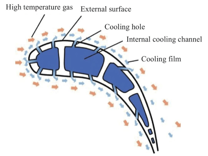
Film cooling technology is a key core technology that supports the improvement of the temperature resistance capability of hot aircraft engine components. It allows the flow of cooling air to be ejected through cooling structures such as film holes to form a film of cooling air covering the surface thereof. hot components to protect them from high temperatures. Taking turbine blades as an example, the principle of film cooling is shown in Figure 1. The processing precision and hole quality of the air film determine the reliability of turbine blades, which in turn affects the safety of the entire aircraft engine. Therefore, extremely strict acceptance requirements are imposed on air film holes, and their manufacturing technology is also questioned. In terms of machining accuracy, the main evaluation factors include hole diameter, hole position, roundness, cylindricity, axis vector angle, roughness and wall integrity of the hole, etc., which determine the cooling air flow, outlet position and angle, jet speed, etc. ., and thus affects the effectiveness of the cooling air film coverage. In terms of processing quality, we mainly focus on the shape and depth of defects in the hole wall/orifice formed by different hole making processes. Excessive defects can cause the blade to break when subjected to complex alternating loads. According to incomplete statistics, more than half of engine failures are related to damage and breakage of engine blades.
Figure 1 Block diagram of the film cooling principle of turbine blades
Figure 1. Schematic illustration of film cooling technology of a turbine blade
The base material of turbine blades is generally made of high temperature alloy materials that are difficult to process. The diameter of air film holes is generally 0.3-0.6mm, especially for large angle oblique holes, depth to diameter ratio. can reach 13:1. Therefore, special processing methods are generally used to process air film holes, including electric discharge machining (EDM), electrochemical machining (ECM) and laser processing.[3-4]. With the diversified development of blade structures and drilling needs, different drilling processes have also developed rapidly, showing a situation in which a hundred schools of thought compete. However, the development of air film hole detection technology is slightly slow.[5]. The reason is on the one hand related to the difficulty of collecting data on the geometric size and metallurgical quality of small holes, and on the other hand it is also related to the large number of air film holes in a single blade and difficulty in matching the production rate of hole making. In fact, it is not realistic to detect all characteristic elements from all holes in the air film. The high-pressure turbine blades of high-performance aero engines alone contain tens of thousands of air film holes. It therefore depends on the precision and quality of the holes made. depends more on the maturity of the manufacturing process and stability. In addition, as the performance requirements of aero engines increase, the gas turbine inlet temperature continues to increase, placing higher requirements on air coverage efficiency. cooling. Hole design has also evolved from early simple straight round holes to complex special-shaped holes, such as dustpan holes, cone holes, teardrop holes, cat ears holes , etc.[6-7]which poses a double challenge in terms of method of hole making process and assessment of manufacturing conformity.
In recent years, the field of aviation has developed vigorously, and the technology of manufacturing and detecting holes in air film has also triggered a research boom. This article reviews the advanced progress and application of typical hole making processes, and conducts trend analysis and summary. on the development of design requirements, further emphasizing that the manufacturing and air film hole detection technology The development direction of film cooling related technologies.

1. Air film hole manufacturing process
1.1 Making EDM holes
EDM hole making is currently the most mature and widely used process method in the field of turbine blade hole making. It has high processing efficiency and good stability. Based on the pulsed spark discharge between the tool and the workpiece (positive and negative electrodes), the material to be processed is engraved to achieve the processing effect of size, shape and surface quality specific to the part.[8]. The current and pulse width in the EDM holemaking parameters determine the size of the single pulse energy, which has a significant impact on the processing quality. The pulse stop (i.e. pulse interval time), internal flush fluid pressure, and discharge product output (i.e. residual ). The transportation process is closely related, so it also has a great impact on the quality of the hole wall and the processing efficiency. In fact, EDM machining technology can show its talents in the field of hole making, through the mature application of hollow tubular electrodes, which solves the problem of slag removal in the processing of small holes with large aspect ratios.
Figure 2 is a schematic diagram of the high-speed EDM small hole machining process. The discharge at the electrode tip continuously erodes the metal matrix material at the bottom of the hole. The hollow tubular electrode allows high pressure internal flushing fluid to circulate. and transport the residue generated by the landfill to prevent it from settling in the hole. Accumulation occurs at the bottom of the hole, thereby advancing the pulse discharge process steadily and continuously downward. Since EDM machining mainly removes material by hot melting, thermally induced defects, such as remelt layers, inevitably form on the hole walls. Some researchers previously believed that thermal defects could cause cracks to appear in the blade hole walls after long-term service, which could further expand under alternating loads, causing the blade to break .[9]. However, although the recast layer on the hole wall formed by different EDM holemaking equipment and processes can only be distinguished by the thickness of the recast layer on the mesoscopic scale, the microstructural morphology can vary significantly.
Dong Tao et al.[10]It has been reported that the recast layer formed by EDM of high-temperature alloys contains a large number of micropores, cracks and other defects, as well as cellular dendrite interfaces formed between different melt pools. However, this research group developed low temperature and high pressure internal fluid and narrow pulse width high frequency power supply, and, on the basis of high temperature single crystal alloy epitaxial growth technology, formed a recast layer of single crystal pore wall. , which is supersaturated and fully consistent with the orientation of the solid solution matrix with FCC network structure (Figure 3, Figure 4). Heat treatment is further used to control the precipitation of the γ’ phase inside the single-crystal recast layer, forming a pore wall fully consistent with the structure of the single-crystal matrix and completely eliminating the recast layer.[11]. However, it is undeniable that the microscopic holes and rough surfaces of the hole walls inside the recast layer cannot be removed by heat treatment and structural control. Compared to the existence of these geometric defects in the recast layer, these factors are more likely to be related to. failure. It is necessary to attract deeper attention.

Figure 2 Schematic diagram of the high-speed EDM small-hole machining process based on hollow tubular electrodes[2]
Figure 2. Schematic illustration of EDM drilling via tubular electrode[2]

Figure 3 Diffraction points of a single crystal superalloy epitaxial growth matrix and a recast layer
Figure 3. Diffraction pattern of single-crystal superalloy matrix and adjacent single-crystal recast layer formed by epitaxial growth

Figure 4 Microscopic morphology of the recast layer of the hole wall controlled by heat treatment
Figure 4. Microstructure of the hole wall of the recast layer formed by heat treatment
1.2 Production of electrochemical holes
At present, the electrochemical machining processes that can be relatively maturely applied to blade hole manufacturing include electrohydraulic beam (Fig. 5) and electrolysis EDM (Fig. 6) composite processing. Electrohydraulic beam treatment involves inserting an electrode wire into a hollow glass tube. The acidic electrolyte flows from the tip of the glass tube under pressure to form circulation, and then removes the treated material according to the principle of electrochemical corrosion. The advantage of electrochemical treatment lies in controlling thermally induced defects, but in acidic electrolytes, the γ phase of single crystal superalloys will be preferentially corroded compared to the γ’ phase, causing the hole wall to inevitably form a layer electrochemical corrosion. EDM-electrolysis hybrid machining replaces the high-pressure internal flushing fluid of the EDM hole machine from deionized water with saline solution, and then removes the recast layer from the hole wall by the electrolysis reaction on the side wall while discharging onto the EDM. advice.
Since the entrance section of the hole undergoes electrolytic corrosion for a longer period of time than the exit section, the removal effect of the recast layer in the entrance section is generally better, while the recast layer which has not been completely eliminated remains in the output section. Another advantage of electrochemical treatment is the blunting effect on the sharp corners of the orifice. If the intersecting lines formed by the air film hole wall and the inner and outer surfaces of the blade are not chamfered, they may be damaged after long-term service. Stresses are concentrated at the sharp corners of the hole and cracks appear particularly severe for the sharp edges of large inclined holes. However, it is undeniable that the rupture of the glass tube processed by the electro-hydraulic beam can make the air film hole too large; EDM-electrolysis composite processing cannot yet be applied to industrial production in terms of quality and technological control. maturity At the same time, the treatment of electrochemical waste is also an issue that needs to be considered comprehensively.

Figure 5 Schematic diagram of the production of electrohydraulic beam holes[12]
Figure 5. Schematic illustration of electro-flux machining[12]

Figure 6 Schematic diagram of composite EDM-electrolysis machining[13]
Figure 6. Schematic illustration of hybrid EDM and ECM process[13]
From the perspective of manufacturing capabilities, the glass tube electrodes involved in electrohydraulic beam hole manufacturing and the hollow tube electrodes used in electrolysis composite EDM machining are only suitable for processing simple straight round holes . As mentioned before, the blade orifice expansion section is designed into special-shaped complex structures such as dustpan shape, water drop shape, water drop shape, etc. a cat’s ear, etc., in order to better cover the surface of the blade after emitting cold air. and electrochemical treatment is not suitable for special-shaped holes and is destined to be unable to adapt to the inevitable trend of increasing gas turbine inlet temperature.
1.3 Making laser holes
In order to improve the thermal carrying capacity of the blades, high-pressure turbine guide blades and working blades of high-performance aerospace engines need to be covered with thermal barrier coatings. The surface material is usually zirconia ceramic, while traditional EDM and EDM. Electrochemical treatment is only suitable for processing conductive metal materials, the process is formulated as: “first make a hole, then coat”. Using the electron beam physical vapor deposition (EB-PVD) process to coat the surface thermal barrier coating will cause the coating to build up at the orifice, causing problems such as shrinkage and clogging, and the airflow direction will deviate from the design requirements, affecting the effectiveness of the cooling air film coverage[14](Figure 7).
The laser is not selective to the material being processed, allowing it to make single holes on high-temperature alloys with thermal barrier coatings, thereby realizing a new processing method of “coat first then make holes”, which effectively improves the conformity of air film hole design and manufacturing for blades with thermal barrier coating[15-16]. Additionally, the blades after service are affected by impurities such as volcanic ash inhaled through the engine inlet, forming a layer of spinel deposits (CMAS for short) composed of oxides of Ca, Mg, Al and Si at the surface of the blades. In severe cases, it may cause shrinkage holes and clogged holes, and laser treatment can also solve the problem of removing non-conductive CMAS deposits, which is of irreplaceable importance.

Figure 7 Schematic diagram of deviation in airflow injection direction caused by shrinkage cavities in thermal barrier coating
Figure 7. Schematic illustration of jet path deviation induced by hole removal during thermal barrier coating
The quality of the hole production is inseparable from the pulse width of the laser. Nanosecond, picosecond and femtosecond lasers are generally suitable for processing blade air film holes. The duration of a single nanosecond laser pulse is longer than the relaxation time of the electronic lattice. After absorbing laser energy, the electrons transfer more heat to the lattice, resulting in thermally induced defects such as reflow layers on the hole walls. The single pulse duration of the femtosecond laser and narrow pulse width picosecond laser is shorter than the relaxation time of the electronic grating. The electrons absorb the energy and then cannot transfer it to the lattice. Under the action of auxiliary air blowing, the material is peeled off. die to achieve high precision, The effect of “cold working”[17-18]. However, under ultra-strong laser irradiation, the high-density plasma agglomerates in the hole, forming a strong shielding and scattering effect on subsequent lasers, seriously limiting the processing efficiency of small holes with d-ratios. ‘appearance high, and the walls of the hole also tend to form. Wavy, ridge-shaped structure (Figure 8). By adding cutting holes after laser punching, the ridge structure can be eliminated to a certain extent and the roughness of the hole wall can be improved, but this will undoubtedly reduce production efficiency. In contrast, the femtosecond laser and galvanometric system that controls the movement of the light plate are relatively expensive and sensitive to environmental fluctuations in the workplace. We still need to continue working on the equipment and technology to make it suitable for batch processing. manufacturing of blade holes in a factory environment.

Figure 8 Wall profile of precision femtosecond laser cutting hole
Figure 8. Hole wall surface profile by femtosecond laser drilling and finishing
Regardless of the drilling method, some form of energy is applied to the material being processed, so that the material is excited to a higher energy state and then combined with the fluid to transport and remove residue at high energy. the hole. Matching energy application and transportation is the ideal state for making holes. If the transport is stronger than the energy application, the energy must be increased to improve the treatment efficiency; if the energy application is stronger than the transport, energy will accumulate in the hole and thermal defects will inevitably form. For small holes with a high depth-to-diameter ratio, the deeper the hole, the more difficult it is to ensure the above two processes, especially the ability to transport tailings outward. In treatment methods such as electric spark and electrohydraulic beam, it is the use of hollow tubular electrodes that ensures the circulation characteristics of the liquid medium.[19]While laser holemaking uses auxiliary air blowing, the ability to transport residue into the hole decreases rapidly with the increase of holemaking depth, which fundamentally limits the application of laser holemaking. laser holes in small holes with high aspect ratios. The advent of water-guided lasers has solved this bottleneck problem to some extent. The laser propagates by total reflection in the micro-water jet, similar to an optical fiber. The powerful water jet strengthens the circulation flow of the medium in the hole, thus improving the depth to diameter ratio of the hole. It should be noted that water-guided lasers generally use nanosecond light sources, and there is always a recast layer on the hole wall of the treated air film.
In summary, different drilling methods have their own advantages and disadvantages in terms of precision, quality, cost and processing efficiency. Therefore, domestic and foreign researchers have triggered a research boom in composite processing. Long and short pulse laser composite processing is based on two sets of nanosecond and femtosecond laser light sources. The two laser beams share the optical path and coaxial output. In the punching stage, the nanosecond laser is used to achieve rapid perforation. hole repair stage, the femtosecond laser makes it possible to drill holes containing defects. The walls are refined, thus considerably reducing production costs while guaranteeing quality. Laser-EDM hybrid processing also uses the technical route of rapid EDM perforation and fine hole wall repair with femtosecond laser. However, due to differences in processing methods, it is difficult to hold the blades in place for processing, requiring repeated high-precision positioning. to resolve. Zero point positioning tooling is used to avoid positioning errors caused by secondary clamping of blades. Combined with the auxiliary blade posture confirmation system, the repeated positioning accuracy can only be achieved by 0.01mm. In addition, laser drilling can also be used to remove the ceramic coating accumulated on the blade holes from “coating first then making holes”, thus avoiding the problems of removal and hole blocking caused by the processes. traditional, but the principle is that the hole making machine tool has a sufficiently high level of spatial positioning accuracy and accurately transmits the hole coordinates and workpiece posture to the laser equipment.
2. Air film hole post-processing
As mentioned before, the sharp corners of the air film holes form local stress concentrations, which can easily cause the holes to crack during service. Therefore, removing sharp angles from the ports is particularly important to improve blade reliability. External port chamfering can be processed by EDM milling, laser spot path planning, magnetic grinding, abrasive flow, etc. The choice of magnetic needles for magnetic grinding is very important. If the diameter of the needle is too large, the chamfering effect will not be obvious, while if the diameter is too small, it may penetrate the hole or even fall into the internal cavity of the needle. Therefore, the optimization of the magnetic grinding process not only includes the motor speed and processing time, the size and shape of the magnetic needle also have a significant impact on the chamfering effect.[20-21]. Abrasive flow processing is not only suitable for chamfering the outer hole, but also can be used to chamfer the hole on the inner cavity side of the blade, while polishing the surface of the hole wall.[22](Figure 9) However, care must be taken in how to remove the abrasive after processing so that it does not block the internal cavity of the blade and does not form excess material. Therefore, liquid abrasive is more suitable for hollow blades with complex cooling; channels.
The abrasive flow processing process parameters mainly include pressure and time (number of cycles), while the factors that affect the chamfer size also include abrasive viscosity, abrasive particle size and concentration.[23]Since the abrasive flow removes the material in the form of plowing, it has higher requirements on the initial hole opening and hole wall condition. If there are geometric defects such as opening gaps, hole wall edges, steps, etc., the size of the defects can be further enlarged after grinding processing. Additionally, in response to the need to remove the recast layer from the hole wall, chemical grinding can also be used for post-processing.[24]。

Figure 9 Morphology of chamfering of the hole before and after abrasive flow treatment of the hole with air film
Figure 9. Abrasive flow processed hole orifice contour profile comparison
3. Detection of holes in the air film
Air film hole inspection includes two aspects: hole wall quality and geometric size. Hole wall quality inspection mainly relies on cutting metallography method. Generally, the air film hole processing process is defined as a special process, and special process confirmation of the hole making process parameters is required. Metallographic inspection includes recast layer of hole wall, microcracks, heat affected zone, intermittent beads, corrosion/oxide layer, ridges/steps of hole wall, roughness of the wall of the hole, etc.[25]. The geometric dimensions of air film holes include pore diameter, hole position, hole shape, etc. Among them, the diameter of the hole is generally detected using the pass stop method of the pin gauge, but the pin gauge measures the length of the minor axis of the minimum cross section of the hole, which is greatly affected by the roundness and taper of the hole; the hole position is usually detected using the standard prototype visual comparison method, but for blades with high acceptance requirements for hole position accuracy, a five-axis measuring machine equipped An optical imaging probe can be used for inspection.[26]Hole size conformity detection is difficult because the metallographic method is only suitable for observing the profile of a certain cut section, while laser confocal detection is difficult for completely scanning the wall profile, so inspection Small focal length industrial CT becomes the important technical evaluation hole in the manufacturing conformity processes of shaped elements[27]. Additionally, industrial CT is also suitable for wall damage detection. Wall damage includes not only protection against surface damage of the hollow blade sidewall, but also protection of cooling structures such as interior cavity partitions, ribs, and spoiler columns (Figure 10).

Figure 10 The hole wall profile of the special-shaped air film obtained by industrial CT scanning
Figure 10. Contour profile of a shaped hole measured by an industrial CT system
The development of sensing technology provides an important basis for realizing adaptive blade processing. Only by accurately collecting the characteristic elements of air film holes can an adjustment processing strategy be formed, thereby compensating for individual differences. There is a casting gap in the turbine blade profile when formulating the adjustment processing strategy, the air film hole jet angle (the angle between the axis of the hole and blade profile) and the relative position between the holes of the air film must be completely. taken into account. The side hole of the inner cavity after adjustment should also be provided. The exit position should avoid cross holes, cross holes, etc. Digital twins provide a technical method for predicting treatment status. The effect of adaptive processing can be checked in the virtual world and then returned to the real world to complete processing after confirmation. This will become an important technology development trend in deep integration. blade manufacturing and inspection in the future.[28]。
4. Conclusion
EDM hole making has low cost and high efficiency, and will long be used as the basic process method for making holes in high temperature alloy blades. Further development includes EDM milling, combination with other process methods and the construction of intelligent systems. electrical machining production lines. Electrochemical hole fabrication is difficult to keep up with the trend of developing special-shaped hole patterns, and its manufacturing capabilities need to be further explored and developed. However, it will still play a decisive role in treating small holes in other areas. With the demand for coated blades, repairing clogged blades after service, and making holes for ceramic-based composite blades, laser processing has become an inevitable choice due to its non-selective nature of the material to be processed. large depth-to-diameter ratios and small Hole processing capacity is insufficient and systematic and in-depth process research needs to be carried out.
Air film hole chamfering has a great impact on the vibration fatigue performance of blades and has good prospects for promotion and application. However, air film hole detection should form a complete standard method system to promote adaptive processing and intelligent manufacturing. technology in the field of blade hole manufacturing.
Daguang focuses on providing solutions such as precision CNC machining services (3-axis, 4-axis, 5-axis machining), CNC milling, 3D printing and rapid prototyping services.


