Skip to content
Image WeChat_20230726165631.png

CNC Knowledge: Skills in machining worm gears on CNC lathes, this type of programming is very practical

Worm screws generally have a large pitch. Due to the characteristics of their tooth profile, the contact surface between the cutting edge and the workpiece is large. During processing, it is very easy to damage the cutting tool due to the extrusion of iron filings in between. the workpiece and the cutting tool. Although the […]

Content Navigation

Worm screws generally have a large pitch. Due to the characteristics of their tooth profile, the contact surface between the cutting edge and the workpiece is large. During processing, it is very easy to damage the cutting tool due to the extrusion of iron filings in between. the workpiece and the cutting tool. Although the operator can use tools with flexible tool shanks and feed with small cutting depth, the above problems cannot be fundamentally solved.

The same problem arises when machining worm gears on CNC lathes. The machine tool will never automatically stop due to tool chipping, so this problem is even more difficult to solve. Ordinary horizontal hand-operated lathes can be flexibly controlled by the operator according to the cutting situation, and can even retract the tool halfway during processing, avoiding a worse situation.

A method given below is to use the rigid processing method of CNC lathes and its precise positioning function to synthesize the two side lines of the trapezoid using the method of “connecting points to form a line”, thus effectively solving this issue.

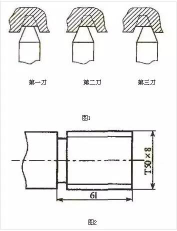
Cutting tools can be made of carbide forming tools. This cutting method turns one knife into three, reducing cutting resistance. The schematic diagram is shown in Figure 1. This method is actually a flexible use of the left and right cutting method. The author changed it to “center, left, right” cut, because if you don’t make a cut from the middle first, the iron filings will still grip the surface. cutter. This is derived from reality in conclusion.

Different from the left and right cutting method of non-CNC lathes, “center, left and right” cutting on CNC lathes requires precise calculations. This calculation takes a little time, but it results in improved processing efficiency and peace of mind during. work. The cutting speed can be selected between 70 and 90 m/min and the cutting depth ap=0.1 to 0.15 mm (depending on the performance of the machine tool, its suitability depends on the thickness and the color of iron shavings).

The coordinate calculation method is shown below, see Figure 2.
cot=20°=1:0.364, i.e. when feeding 0.1 mm in Z direction decreases and increases by 0.0364 mm. You can first list the values ​​as shown in the following table for easier programming.
Photo WeChat_20230726165632.jpg

Cutting left and right on the CNC actually means changing the Z coordinate of the starting point when threading. This must be kept in mind. The following takes Figure 2 as an example to give a program and corresponding instructions. The thread order is G92, the end face of the workpiece is the zero position in the Z direction, and the thread pitch is 8mm.

N110 GOO X55 Z10 quickly locates the thread starting point
First car cut N120 G92 X49.8 Z-60 F8 to X49.8
N130 GO1 W-1.42 F1 Change thread starting point
N140 G92 X49.8 Z-60 F8 left car
N150 G01 Z10 F1 Return to starting point
N160 W1.42 Change thread starting point
N170 G92 X49.8 Z-60 F8 right side of car
N180 G01 Z10 F1 Return to starting point in Z direction
First car cut N190 G92 X49.6 Z-60 F8 to X49.6

As shown in the example above, “middle, left and right” turning is carried out several times, cutting is easy, and chip evacuation is smooth. The goal of “connecting the dots to form a line” was achieved, transforming the limitations of the CNC into strengths. If coolant is added to remove iron shavings during cutting, the effect will be better.

Additionally, when processing parts such as square threads, you can also use turning tools narrower than the width of the groove and program using the above method. However, the program is much simpler and does not require a lot of calculations. is also very satisfying.

Daguang focuses on providing solutions such as precision CNC machining services (3-axis, 4-axis, 5-axis machining), CNC milling, 3D printing and rapid prototyping services.

Welcome to GreatLight Metal,Maximum Processing Size 4,000 mm

Precision Machining CNC Quote Online

Loading file

Upload Click here to upload or drag and drop your model to the canvas.

The model is too large and has been resized to fit in the printer's build tray. [Hide]

The model is too large to fit in the printer's build tray. [Hide]

The model is too large, a fitting printer is selected. [Hide]

The model is too small and has been upscaled. [Hide]

Warning: The selected printer can not print in full color [Hide]

Warning: obj models with multiple meshes are not yet supported [Hide]

Warning: Unsupported DXF entity  [Hide]

Warning: could not arrange models [Hide]


File Unit:      
Scale:
%
L × W × H:
X: × Y: × Z:  cm 
Rotation:
X: ° Y: °  

Model Stats:

Material Volume: cm3
Support Material Volume: cm3
Box Volume: cm3
Surface Area: cm2
Model Weight: g
Model Dimensions:
x x cm
Number of Polygons:
Number of Shapes:
Total Path: cm
⚡ Instant Quote for Precision Manufacturing

Submit your design files (STEP/IGES/DWG) and receive a competitive quote within 1 hour, backed by ISO 9001-certified quality assurance.

📋 How It Works

  1. Upload & SpecifyShare your 3D model and select materials (Aluminum/Stainless Steel/Titanium/PEEK), tolerances (±0.002mm), and surface treatments.

  2. AI-Powered AnalysisOur system calculates optimal machining strategy and cost based on 10+ years of automotive/aerospace data.

  3. Review & ConfirmGet a detailed breakdown including:
    - Volume pricing tiers (1-10,000+ units)
    - Lead time (3-7 days standard)
    - DFM feedback for cost optimization

Unit Price: 

Loading price
5 Axis CNC Machining Equipment
4 Axis CNC Machining Equipment
3 Axis CNC Machining Equipment
CNC Milling & Turning Equipment
Prototype and Short-Run Injection Moldings Exact plastic material as final design
Volume Metal Die Casting Services - Precision Cast Parts
Bridge the Gap From Prototype to Production – Global delivery in 10 days or less
Custom high-precision sheet metal prototypes and parts, as fast as 5 days.
Custom Online 3D Printing Services
Design Best Processing Method According To 3D Drawings
Alloys Aluminum 6061, 6061-T6 Aluminum 2024 Aluminum 5052 Aluminum 5083 Aluminum 6063 Aluminum 6082 Aluminum 7075, 7075-T6 Aluminum ADC12 (A380)
Alloys Brass C27400 Brass C28000 Brass C36000
Alloys Stainless Steel SUS201 Stainless Steel SUS303 Stainless Steel SUS 304 Stainless Steel SUS316 Stainless Steel SUS316L Stainless Steel SUS420 Stainless Steel SUS430 Stainless Steel SUS431 Stainless Steel SUS440C Stainless Steel SUS630/17-4PH Stainless Steel AISI 304
Inconel718
Carbon Fiber
Tool Steel
Mold Steel
Alloys Titanium Alloy TA1 Titanium Alloy TA2 Titanium Alloy TC4/Ti-6Al 4V
Alloys Steel 1018, 1020, 1025, 1045, 1215, 4130, 4140, 4340, 5140, A36 Die steel Alloy steel Chisel tool steel Spring steel High speed steel Cold rolled steel Bearing steel SPCC
Alloys Copper C101(T2) Copper C103(T1) Copper C103(TU2) Copper C110(TU0) Beryllium Copper
Alloys Magnesium Alloy AZ31B Magnesium Alloy AZ91D
Low Carbon Steel
Alloys Magnesium Alloy AZ31B Magnesium Alloy AZ91D
ABS Beige(Natural) ABS Black ABS Black Antistatic ABS Milky White ABS+PC Black ABS+PC White
PC Black PC Transparent PC White PC Yellowish White PC+GF30 Black
PMMA Black PMMA Transparent PMMA White
PA(Nylon) Blue PA6 (Nylon)+GF15 Black PA6 (Nylon)+GF30 Black PA66 (Nylon) Beige(Natural) PA66 (Nylon) Black
PE Black PE White
PEEK Beige(Natural) PEEK Black
PP Black PP White PP+GF30 Black
HDPE Black HDPE White
HIPS Board White
LDPE White
This is a finish of applying powdered paint to the components and then baking it in an oven, which results in a stronger, more wear- and corrosion-resistant layer that is more durable than traditional painting methods.
No coating required, product’s natural color!
This is a finish of applying powdered paint to the components and then baking it in an oven, which results in a stronger, more wear- and corrosion-resistant layer that is more durable than traditional painting methods.
This finishing option with the shortest turnaround time. Parts have visible tool marks and potentially sharp edges and burrs, which can be removed upon request.
Sand blasting uses pressurized sand or other media to clean and texture the surface, creating a uniform, matte finish.
Polishing is the process of creating a smooth and shiny surface by rubbing it or by applying a chemical treatmen
A brushed finish creates a unidirectional satin texture, reducing the visibility of marks and scratches on the surface.
Anodizing increases corrosion resistance and wear properties, while allowing for color dyeing, ideal for aluminum parts.
Black oxide is a conversion coating that is used on steels to improve corrosion resistance and minimize light reflection.
Electroplating bonds a thin metal layer onto parts, improving wear resistance, corrosion resistance, and surface conductivity.
This is a finish of applying powdered paint to the components and then baking it in an oven, which results in a stronger, more wear- and corrosion-resistant layer that is more durable than traditional painting methods.
Please provide additional text description for other surface treatment requirements!
Material
Material
  • CNC Metals
    • Aluminum
    • Brass
    • Stainless steel
    • Inconel718
    • Carbon Fiber
    • Tool Steel
    • Mold Steel
    • Titanium
    • Alloy Steel
    • Copper
    • Bronze
    • Low Carbon Steel
    • Magnesium
  • CNC Plastics
    • ABS
    • PC
    • PMMA (Acrylic)
    • PA (Nylon)
    • PE
    • PEEK
    • PP
    • HDPE
    • HIPS
    • LDPE
Printer
Printer
  • CNC Metals
    • 5 Axis CNC Machining
    • 4 Axis CNC Machining
    • 3 Axis CNC Machining
    • CNC Milling & Turning
    • Rapid Tooling
    • Metal Die Casting
    • Vacuum Casting
    • Sheet Metal Fabrication
    • SLA 3D Printing
    • SLS 3D Printing
    • SLM 3D Printing
  • Rapid Prototyping
    • Design Best Processing Method According To 3D Drawings
Post-processing
Post-processing
Finalize
The world's first CNC machining center that dares to provide free samples!

Free for first product valued at less than $200. (Background check required)

Precision Machining CNC Quote Online

15 Years CNC Machining Services

When you’re ready to start your next project, simply upload your 3D CAD design files, and our engineers will get back to you with a quote as soon as possible.
Scroll to Top

Get The Best Price

Send drawings and detailed requirements via Email:info@glcncmachining.com
Or Fill Out The Contact Form Below:

All uploads are secure and confidential.