With the rapid development of the automobile transmission industry, the requirements for gears as essential components are also increasing. Requirements such as light weight, low cost, low energy consumption and new materials have become new challenges in its development. It was decided to try to make involute helical gears using powder metallurgy technology.
Powder metallurgy technology has the potential to reduce the weight of gear parts by 8-20% and can also reduce the inertia of synchronous mechanisms in gearboxes such as MT, AMT and DCT. At the same time, the product processing line will be shortened, and the workshop area, equipment investment and energy consumption required for gear manufacturing will all be saved compared with traditional gear processing processes in steel. This technology could bring huge changes to the gear manufacturing industry in the future.
Advantages of powder metallurgy gear technology: ① The overall material utilization rate can reach more than 95%; ② No or very little cutting processing is required; ③ The parts have stable dimensions, good consistency and high precision; efficiency, suitable for mass production, the required cost is lower than that of cutting machining.
01
Application Analysis of Powder Metallurgy Gears
Since the mechanical properties of powder metallurgy materials may be lower than those of steel parts under the same conditions, the “fourth input gear” in a mature front-wheel drive six-speed manual transmission was selected (number of teeth: 31, modulus 1.85, pressure angle 15°, helix angle 34°), processed into powder metallurgy gears, and its process and performance were studied and analyzed, and a brief comparative analysis was conducted with case-hardened steel gears.
Material selection
Since the selected iron-based powder needs to be compacted, sintered and surface densified, it must meet the following requirements.
(1) It has good fluidity and pressability, ensuring that all parts of the pressed gear can achieve the density required by the design.
(2) After the powder blank is sintered, its size change should be as close to zero as possible, and the hardness should be between 100-170 HV10 to prevent the parts from cracking due to excessive hardness .
(3) After the material is densified and laminated, a theoretical non-porous layer can be formed on the tooth surface.
(4) The selected material should have a certain degree of hardenability to ensure that the tooth surface can reach the required design hardness after heat treatment, and the core of the workpiece should have high toughness.
(5) The selected iron-based powder must meet the requirements of surface heat treatment.
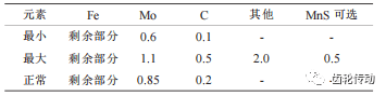
Based on the above factors, Astaloy 85 Mo+C pre-alloyed iron powder was selected and its material composition is shown in Table 1.
Table 1 Powder metallurgy Material composition Astaloy 85 Mo+C w (%)
Material performance analysis
In terms of material properties, in order to improve the Young’s modulus E, Poisson’s ratio ν and fatigue performance of powder metallurgy parts, powder metallurgy gears need to use special processes to obtain a surface sufficiently tight on the tooth surface and the tooth root surface. contours, then moves towards the core. There is a dense layer approximately 1 mm deep with gradually decreasing density in the central direction (as shown in Figure 1).

Figure 1 Dense layer of powder metallurgy gears
After analysis and testing, the dense layer can be roughly divided into five layers, with each layer measuring approximately 0.2mm. Using formulas (1) and (2), important parameters that can be used for analysis and simulation calculation are obtained, as shown in. Table 2:

In the formula, ρ is the density of the powder part; E0, ρ0 and ν0 are respectively the Young’s modulus, density and Poisson’s ratio of the steel part.
Table 2 Young’s modulus and Poisson’s ratio in different density zones

structural design
Powder metallurgy manufacturing uses integrated casting technology to pour metal powder into a special rigid closed mold. Therefore, redesigning the part structure can eliminate some empty grooves on steel parts and make the structure more compact.
At the same time, the following issues should be considered when designing the structure.
(1) Avoid local thin-walled materials to facilitate powder loading and compaction and avoid cracking.
(2) Try to avoid designing grooves and counterbores on the sidewalls, because smooth sidewalls promote compaction or reduction of residual materials.
(3) Try to design a relatively simple and symmetrical shape structure to avoid excessive changes in cross section, narrow grooves, spherical surfaces, etc., to facilitate mold manufacturing and compaction.
(4) Transition joints on each sidewall shall be designed with rounded corners to avoid sharp edges and prevent stress concentration in the mold and compaction.
Calculation of fatigue resistance by simulation
Due to the presence of pores inside traditional powder metallurgy parts, the material property parameters of traditional powder metallurgy parts should be lower than those of steel parts under the same conditions, that is- that is, surface flexural fatigue resistance and contact fatigue resistance are often worse. than those of case-hardened steel gears. After the surface densification treatment, the surface of the workpiece in contact with the rolling die is almost completely dense. After reasonable heat treatment and gear parameter design optimization, its bending fatigue resistance and contact fatigue resistance can fully meet the relevant service life requirements. close to the level of case-hardened steel parts.
Referring to the GB/T 14230 gear bending fatigue strength test method, the powder metallurgy bending fatigue SN curve was obtained and compared with ISO6336 16Mn-Cr5 ( MQ), the comparison results of the bending resistance of gears were obtained, as shown in Figure 2. Judging from the results, the resistance to the bending fatigue of powder metallurgy gears is close to that of case-hardened steel.

Figure 2 Fatigue and bending resistance of gears
02
Research on powder metallurgy gear process
Usually, the density of components produced by ordinary powder metallurgy processes that use only one pressing and one sintering is basically less than 7.2 g/cm3. For example, in applications such as shift drum gears and timing hubs in transmissions, their surfaces and there is a. large number of pores inside, which significantly reduces its fatigue resistance. Transmission gears must withstand high loads at high speeds and are prone to failures such as broken teeth and pitting corrosion on the tooth surface. For the above reasons, powder metallurgy transmission gears need to properly select materials, then undergo surface densification treatment after pressing and sintering processes, and finally heat treatment and subsequent machining to obtain excellent mechanical properties.
The new four-speed input gear, after combining the powder metallurgy process with the traditional gear processing process, the process is shown in Figure 3. It can be seen from this process route that the process route is significantly shortened, processing complexity is reduced and significant savings can be achieved.

Figure 3 Powder metallurgy gear processing technology
“Surface densification treatment”
This process is completed by a special gear rolling machine, as shown in Figure 4. Two specially designed active rolling gears, based on the involute geometry of the gear, clamp the “pre-machined gear” in the middle . The rolling gear rotates at high speed, and at the same time applies pressure to the tooth surface and tooth root surface of the “pre-gear”, resulting in a dense surface rolling effect.

Figure 4 Gear surface densification treatment
“Thermal treatment”
The gear after surface densification must be carburized to improve its mechanical properties. The process parameters are shown in Figure 5.

Figure 5 Heat treatment process
After heat treatment, the surface hardness of parts can reach 560~660 HV10 and the central hardness will reach 250~320 HV10. The comprehensive performance basically meets the usage requirements.
“Car hard after hot”
First of all, sharp burrs must be removed. Since powder metallurgy technology is powder casting technology, there is a fit gap between the molds. Therefore, when the powder is pressed and molded, the molded part will have a filling effect at the mold fitting gap, resulting in a small amount of burr. . Suitable machining methods such as roller grinding and sandblasting can be considered to remove these burrs.
“Sharpening teeth”
When powder metallurgy gears undergo surface densification treatment, due to the elasticity and stress release of the material, bending deformation will occur after rolling, resulting in tooth profile alignment errors on the tooth surface. High temperature deformation during heat treatment further increases the corresponding error. The gear honing process is used to eliminate these errors, so that the tooth surface accuracy of powder metallurgy-processed gears is at the same level as that of similar steel gears.
03
Quality Benchmarking
Select and enter a fourth gear steel gear and a powder metallurgy gear (the actual gears are shown in Figures 6 and 7) to compare the quality.

Figure 6 Steel gear

Figure 7 Powder metallurgy gear
quality
The steel part is 0.110 kg, the powder metallurgy part is 0.082 kg, and the mass of the powder metallurgy gear is reduced by 25%;
Tooth root roughness
Since the tool marks of traditional cutting processes are eliminated, the tooth root roughness of powder metallurgy gears after rolling is very good, which is better than that of steel gears processed by hobbing, such as shown in Figure 8.

Figure 8 Tooth Root Roughness Report
Steel gear: Ra=0.445 Rz=2.429
Rmax=3.216
Powder metallurgy gear: Ra=0.349 Rz=2.433
Rmax=2.761
Finished product accuracy of gear teeth
Steel gears and powder metallurgy gears both adopt heat treatment and sharpening process. After testing, the accuracy of the finished tooth surfaces of the two is equivalent and both can reach level 8 of DIN 3961.
Precision of the flower key
The tooth shape and precision of powder metallurgy gears are better than those of steel gears. As shown in Figure 9.

Figure 9 Splined tooth shape
density
Compared with the tight internal structure of steel parts, there are pores inside powder metallurgy parts. The tooth density of each batch of powder metallurgy gears should be inspected and targeted randomly.
Based on Archimedes’ method, it is possible to find a way to analyze and calculate the density of powder metallurgy parts. The steps and principles are summarized as follows.
(1) First prepare cutting equipment, tool accessories, grinding and polishing equipment, optical microscopes and professional cameras.
(2) Cut a standard test block with a mass greater than 5 grams from the tooth and detect the density gradient in the two areas of the index circle and the normal direction of the straight line 30° tangent to the thread root of the tooth. as shown in Figure 10.

Figure 10 Schematic diagram of tooth detection area
(3) Use a light microscope to magnify the affected area 200 times, then use a professional camera to take pictures at an equal distance from the outside (image 1) to the inside (image 5). Figure 11 (Note: Number and size of photos may vary depending on condition of parts).

Figure 11 Partial magnification ×200
(4) The black dots in Figure 11 are pores. Specific software is used to analyze the percentage of area occupied by pores on the unit size photo, and the true density value is calculated according to formula (3).
ρ = 7.83/100% × (100% pore proportion) (3)
Among them, 7.83 g/cm3 is the theoretical maximum density of this powder material.
After analyzing and calculating the spectrum of each zone one by one, the density gradient in the different zones of the room can finally be summarized using graphs. And compare it with the design requirements.
04
Test results
The powder metallurgy input fourth gear gear was assembled into the transmission of the corresponding model and tested on a professional experimental bench according to the durability load spectrum generated by the corresponding vehicle roadmap. Three consecutive transmissions have passed the endurance cycle test twice the operating time of the endurance load spectrum, meeting the service life requirements of this transmission.
05
in conclusion
(1) As a green and environmentally friendly sustainable technology, powder metallurgy gears will achieve higher raw material utilization and lower energy loss. The reduced number of processing steps also means less equipment investment and smaller factory area planning, and its production efficiency is higher and cost-effectiveness is obvious.
(2) Through reasonable design, powder metallurgy gears have sufficient design margin, weight reduction, stress reduction, noise suppression, shock absorption and other capabilities. During the gear design and development phase, engineers have a new choice.
(3) Powder metallurgy gears require the investment of a large number of molds. During the unfrozen design phase, the financial risk of making mold design changes is greater since producing mid- and low-volume parts using the powder metallurgy process is not economical; , it is recommended for large volume demand when used.
Daguang focuses on providing solutions such as precision CNC machining services (3-axis, 4-axis, 5-axis machining), CNC milling, 3D printing and rapid prototyping services.


