A new type of ejector pin device is designed to process thin shafts with small diameter. It can intelligently transform the tailstock into a central frame and change the axial clamping of the tailstock to radial clamping, thereby eliminating the stress on the thin shaft during processing. , deformation and thermal elongation caused by cutting heat to ensure product quality.
PART 1Preface
Small diameter thin shafts are widely used in nuclear power, internal combustion engines, thermal turbines and aerospace manufacturing. Thin shaft turning technology has always been a difficult point in turning processing. After long-term practice accumulation, there are now more and more processing solutions for thin shaft parts. Common methods are to use special equipment, such as tie rod lathes, double turret turning and milling combinations (the upper and lower turrets are turned simultaneously or to use advanced processes, such as auxiliary support, segmented turning, multi-pass turning and); vibration control, etc., according to the slender shaft Choose the appropriate solution according to the requirements of shape, material and processing precision of parts.[1]. However, in actual processing, this is sometimes subject to production conditions and it is necessary to develop a processing plan based on existing conditions. The following is a processing method subject to existing production conditions. Based on a new type of core device, the tailstock is intelligently transformed into a center frame, and the axial clamping force of the tailstock is transformed into the radial clamping force, thereby eliminating the axial clamping force of the tailstock . the need for momentum. The axial force of the shaft eliminates its deformation and thermal elongation caused by cutting force and heat, thereby better guaranteeing product quality.
PART 2 Difficulties of the process
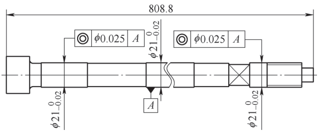
The structure of a new valve stem is shown in Figure 1. It is the company’s valve stem with the largest length-to-diameter ratio. The success of its trial production is related to the future direction of valve stem modification and upgrade. as well as the company’s ultra-supercritical steam turbine[2]Market utilization rate of 660 MW. The length of the valve stem is 808.8mm, the average diameter is about 20mm, the aspect ratio is 40, and the coaxiality is 0.025mm. The valve stem is an ultra thin long stem.[3]Made from high temperature nickel base alloy[4]turning is extremely difficult, it is easy to bend and deform and requires nitriding, and the high temperature environment will increase the degree of bending and deformation of the valve stem. Due to the high requirements for geometric accuracy for part processing, manufacturing is difficult.
Figure 1 Structure of the valve stem
PART 3 Causes of machining deformation of thin shafts
During the machining process of thin shafts, many factors cause the workpiece to deform, including the following aspects.
(1) The influence of the tightening method and the use of tooling Since the rigidity of thin shaft parts is generally poor, the selection of the tightening method and the use of tooling are crucial. Improper clamping, incorrect positioning reference selection, and inappropriate clamping force will result in overpositioning and distortion of the part. At the same time, incorrect use of tool accessories can also cause various forms of deformation, such as “bamboo shape”. “Saddle shape” and “diamond shape”, etc. These problems may result in the part being scrapped.
(2) Influence of material properties and internal residual stresses. The processability of thin shaft parts is largely affected by the material properties. Since a large amount of material must be removed when processing ultra-thin shafts, residual stresses are released when the raw material is removed, destroying the structural balance of the part, thereby causing significant deformation during processing. treatment.
(3) Processing methods and force effects during processing Due to the different structures and shapes of thin shaft parts, different processing methods are used. However, these parts all face common problems during processing, that is, unreasonable processing methods may cause cutting forces to increase, which may cause the workpiece to vibrate.[5]and bending deformation. In addition, because workpieces can automatically vibrate under the action of centrifugal force, cutting forces can also cause bending deformation and vibration. Therefore, determining a reasonable processing method to reduce stress and vibration is the key to improving the quality of turning.
PART 4 Measures to control deformation by machining thin shafts
In order to control deformation when machining thin shafts, the following measures are often taken.
(1) It is very important to use tools to improve the workpiece clamping method. It is very important to choose the appropriate clamping method, such as double top with chicken heart clamp, clamp with one top, clamp with one top. and a holder, a clamp with a holder and a clamp with several clamps. Please wait. Select the appropriate clamping method according to the structure and shape characteristics of the workpiece to improve the rigidity of the workpiece, reduce the stress on the workpiece, eliminate vibration, and minimize and avoid deformation caused by clamping the workpiece, thus ensuring quality treatment of the workpiece.
(2) Reduce the residual stresses of the material step by step. Residual stresses will affect the deformation of the part during the entire processing process. Step-by-step machining can be used, including roughing, semi-finishing and finishing, to gradually reduce the residual stress of the material. In addition, the deformation caused by stress release can also be reduced through heat treatment and aging.[6]。
(3) Optimizing the machining process to reduce stress is the key to reducing the machining deformation of thin shaft parts. To this end, it is necessary to adopt reasonable processing technological methods, including rationally arranging processing procedures, selecting appropriate tool geometry angles, setting appropriate cutting parameters and designing trajectories. tools conducive to reducing deformation. These measures can ensure that the workpiece is less affected by cutting forces and avoid vibration during processing.
PART 5 Process Plan
According to the characteristics of the ultra-thin long shank product, when the parameters of the machine tool, tool and cutting are certain, the most important factor affecting the turning quality is the clamping method, it Therefore the following solutions are proposed from the point of view of the tightening method. . According to the company’s existing equipment, the Mazak QTN200 multi-function CNC lathe with a tailstock and a single center frame was selected. He was inspired by the traditional method of processing thin stems and adopted the “one clamp, one holder and one top” method. treatment (see Figure 2).

Figure 2 Processing diagram of the “one clamp, one holder and one top” method
Through production testing, it was found that high-precision thin shafts need to be processed on general-purpose equipment using the “clamp, support and eject” method, which requires high skills from the the operator, including the skill of using the ejector pin. is very critical. Since thin shafts are easily deformed by axial force and it is difficult to guarantee dimensional and geometric tolerances, which seriously affects product quality, so the focus is on how to eliminate deformation by axial force of thin shafts.
After viewing the information, I found that there is a CNC lathe specializing in processing ultra-thin shafts. This machine tool does not feature a tailstock but comes with numerous center frames. The central frame only has radial clamping force but no axial force. Inspired by this, we came up with the “one clamp, two holders” solution (see Figure 3) to convert the existing tailstock thimble into a center frame function.

Figure 3 Processing diagram of the “one pliers, two paddles” method
After analysis and practice, a new type of adjustable tailstock ejector device was designed. Its structure is shown in Figure 4, which can intelligently transform the tailstock into a central frame and change the axial clamping of the tailstock to radial clamping, eliminating the need for The thin shaft is deformed due to the strength. By controlling the clamping force of the ejector pin, the thermal elongation and deformation caused by stress and cutting heat of the thin shaft during the machining process can be eliminated.

Figure 4 Structure of the new ejection device
1—Socket 2—Ejector pin body 3—Resilient boot 4—Hex socket flat end set screw 5—Lock nut
The bushing is used to stabilize parts extending from the tail of the ejector pin and can be replaced depending on the size of the parts; the main body of the ejector pin is used to match the inner cone of the tailstock;[7]The outer conical surface of the elastic sheath is used to cooperate with the inner cone of the ejector pin body. The elastic sheath can be selected and replaced according to the size of the product. The lock nut is used to achieve axial movement via a threaded connection. the ejector pin body, causing the elastic sheath to deform, causing the workpiece to be clamped; Flat end hexagon socket set screws are used to prevent the lock nut from loosening during machining.
The new ejector pin device allows radial clamping while covering conventional core functions (see Figure 5). The replaceable center is used for tight machining of products using a central hole or an outer dome, and is equivalent to the function of a conventional center. For parts with different specifications, only the sheath or elastic tip needs to be replaced, which improves the utilization rate of the ejector and reduces product manufacturing costs.

Figure 5: The new ejector device is equivalent to the conventional top function
PART 6 Implementation of the process plan
Unscrew the valve stem from φ21 using the “pliers and bracket (center frame)” method![]() mm tightening standard, select an elastic sleeve with an inner hole size of φ21mm. Install each component according to the ejection device diagram. In combination with the movement of the central frame, turn each outer circle separately according to the drawing.[8]。
mm tightening standard, select an elastic sleeve with an inner hole size of φ21mm. Install each component according to the ejection device diagram. In combination with the movement of the central frame, turn each outer circle separately according to the drawing.[8]。
The specific installation steps for the ejection device are as follows.
1) Turn the clamping reference φ21mm via “one clamp and one bracket (middle frame)” method.
2) Select an elastic sheath with an inner hole size of φ21mm according to the outer tightening reference circle rotated by φ21mm.
3) Insert the main body of the ejector pin into the taper hole of the machine tool tailstock to fit it tightly.
4) Referring to the structure diagram of the ejector device (see Figure 4), install the elastic chuck, lock nut, workpiece (adjust the position by moving the tailstock) and adjusting screw flat end hexagonal screw in place in order, and use a wrench to tighten the lock nut, pay attention to the intensity. Use the Allen key to tighten the screw.
5) Use a dial indicator to check the workpiece runout at the ejector pin clamping position to ensure that the ejector pin is installed in place.
The actual installation of the ejector pin on the machine tool tailstock is shown in Figure 6.

Figure 6 The actual installation of the ejector pin on the machine tool tailstock
The new valve stem turning process is as follows.
1) Use the cylindrical turning tool to coordinate the movement of the center frame, and turn the center frame to maintain the reference outer circle in three sections from the end of the chuck to the end of the ejector pin.[9]that is, the reference is tightened by rotating the chuck center frame to the end of the tailstock. After tightening the center frame, the second section of the center frame is rotated in the same manner to maintain the reference by rotating the center frame. of the reference frame, the movement of the central frame is completed. Rotation of the tight reference of the scope to the desired position. Leave a margin for the outer tightening reference circle.
2) Use a dial indicator to detect the runout of the rotated outer reference circle.
3) Move the center frame to the reference outer circle to clamp the workpiece, use a dial gauge to check the runout of the center frame clamping position, and ensure that the runout of the dial gauge is within 0.005 mm before and after tightening.
4) Use a cylindrical turning tool to semi-finish the front and rear parts of the valve stem with the center frame as the boundary, check whether there is a change in the runout of the center frame clamping part and finish turning the front and rear parts of the valve stem to the finished size.
5) Move the middle frame to the processed outer circle, tighten the processed outer circle, and rotate the reference outer circle to the finished product size, then recheck the size.
With the new adjustable tailstock ejector pin, the “one frame and two brackets” processing plan for the valve stem is shown in Figure 7, and the actual trial processing application of the new pin ejection is shown in Figure 8.

Figure 7 Schematic diagram of using the new ejector device to process the valve stem using “one clamp and two holders”

Figure 8 Actual application of trial processing of new ejector pin
PART 7 Effects and benefits of treatment
Three pieces of test valve stems were treated using this solution. Through self-inspection and special supervision, the cylindricity, coaxiality and roughness of the outer surface were inspected. All three pieces were qualified, with a 100% success rate. At the same time, the new ejection device also has the following advantages.
1) The ejector pin is relatively versatile. It not only can realize radial tightening, but also has the function of conventional upper axial tightening and has high versatility.
2) For parts with different specifications, only the elastic sheath or tip needs to be replaced, which improves the utilization rate of the ejector and the applicability of the device.
3) When the tip is worn out, you only need to replace the tip, and the ejector pin body and other components can be reused, thereby shortening the ejector pin manufacturing cycle and reducing costs .
4) Realization of “ingenious change of thimble on the middle frame”, “one clamp, one bracket and one ejection” to “one clamp, two brackets”, changing the axial force to radial clamping, eliminating the axial force of the thin shaft, so as to eliminate stress deformation of the thin shaft and ensure its dimensional and geometric accuracy.
5) By controlling the clamping force of the ejector pin, it can eliminate the thermal elongation of the thin shaft caused by cutting force and heat during processing, eliminate deformation and guarantee quality.
6) Simple structure, practical, safe and high reliability.
7) This processing method can be extended to turning small diameter and thin shaft parts. The ejector pin can be applied to the tailstock of all lathes, which has certain promotion potential and economic benefits.
PART 8Conclusion
Based on the new small diameter thin shaft machining method of ejector pin, the tailstock can be intelligently transformed into a central frame, and the axial clamping of the tailstock can be changed to radial clamping when It is applied to the treatment of thin shafts, thanks to the control of. The clamping force of the ejector can eliminate the thermal elongation and deformation caused by the cutting force and heat of the thin shaft during processing, and find a scientific and reasonable processing solution for shaft processing similar thin. The new ejection device covers the conventional central functions. For parts with different specifications, only the elastic sheath or self-made center head needs to be replaced, which improves the utilization rate of the ejector and reduces costs. The new tailstock ejector device which changes the tailstock of general machine tools from axial clamping to radial clamping has good versatility and promotion value.
Daguang focuses on providing solutions such as precision CNC machining services (3-axis, 4-axis, 5-axis machining), CNC milling, 3D printing and rapid prototyping services.


