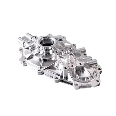
The gasket face is not flat
A cover machined on a 3-axis mill in two setups often comes off the fixture with 0.05 mm of twist. The gasket cannot absorb that. Oil weeps at the corner nearest the last clamp, and the leak returns after every re-torque.

We machine valve covers from 6061-T6 and 7075 billet on 5-axis centers. Gasket faces stay flat, bolt holes line up, and wall thickness holds through the whole run.

Most valve cover failures are not design failures. They are process failures that only appear once the part is torqued down and hot.
A cover machined on a 3-axis mill in two setups often comes off the fixture with 0.05 mm of twist. The gasket cannot absorb that. Oil weeps at the corner nearest the last clamp, and the leak returns after every re-torque.
When the cover is flipped between operations, hole position depends on how well the operator re-datums the part. Two holes end up 0.15 mm apart from the mating flange, and the cover fights the studs during install.
Thin walls are where heat cycles do their damage. If the as-cast or as-machined wall swings between 2 mm and 4 mm, the cover moves differently than the head it sits on. Cracks start at the thinnest section.
A brushed finish with no sealing traps road salt and coolant residue. Within a season the surface pits, and the customer blames the casting rather than the surface prep.
Valve covers are flatness problems first and machining problems second. The process is built around that.

We start by establishing the head-side gasket face as the primary datum. That face gets machined in the first operation while the part still sits on the raw stock, so there is no re-clamping error carried into the critical surfaces.
From that datum, the bolt pattern, the rail faces and the internal baffle pockets are cut in the same or the next setup. Hole-to-hole position stays inside ±0.05 mm across the pattern, which is what lets the cover drop onto the studs without prying.

A valve cover is rarely a box. There are sloped end rails, oil filler necks, PCV ports and internal baffle plates that sit at angles a 3-axis machine reaches only with custom fixtures.
Our 16 simultaneous 5-axis centers cut those features in one continuous setup. The tool reaches the underside of the baffle and the sloped rail without the part ever leaving the vise. Fewer setups means fewer chances for a datum to move.
Alloy choice drives weight, weldability and how the cover behaves under heat cycling.
| Alloy | Best for | Trade-off |
|---|---|---|
| 6061-T6 | General covers, good strength and finish | Not the lightest option |
| 7075 | Thin-wall race covers, high load | Harder to weld, higher cost |
| 6082 | Structural covers, anodizes well | Slightly lower strength than 7075 |
| ADC12 | Die-cast production volumes | Porosity risk in thin walls |
| 5052 / 5083 | Fabricated covers, welded seams | Lower machined finish quality |
A cover project rarely needs only one process. These are the ones we run in-house.
Simultaneous 5-axis cutting for sloped rails, baffles and complex internal pockets in one setup.
Cost-effective routes for flat covers, simple bolt patterns and low-volume runs.
Filler necks, breather fittings and threaded ports turned to spec on mill-turn centers.
Fit-check covers in days before committing to a billet or casting run.
Anodizing, bead blasting, powder coating and laser marking for engine-bay durability.
ADC12 covers for higher volumes when the wall thickness allows it.
Numbers we work to on aluminum engine covers and related housings.
| Parameter | Value | Notes |
|---|---|---|
| Standard tolerance | ±0.005 mm | On critical fits, per drawing |
| Surface finish | Ra 0.8–1.6 μm | Typical machined cover surface |
| Fine finish | Ra 0.2–0.8 μm | Sealing faces on request |
| Max part size | 4,000 mm | Longest travel on large mills |
| Large travel | 4,000 × 400 × 150 mm | Inline and industrial covers |
| Rotary work | Ø400 mm table | Angled faces on 5-axis |
| Inspection | 100% before shipment | Reports on request |
| Runs | 1 to 10,000+ | No minimum order quantity |
Six things that decide whether your cover run goes smoothly. Each one is a number, not a promise.
15 years of aluminum and steel work in Dongguan, with a second plant in Singapore.
±0.005 mm on critical features, verified on the CMM before the run is released.
16 five-axis centers, 12 four-axis mills, 27 three-axis machines and 16 mill-turn centers.
Quotation and free DFM analysis within 12 hours of receiving your files.
Production can begin within 24 hours once the drawing and material are confirmed.
Parts that pass final inspection across production runs.

Covers and housings built to IATF 16949 process controls, with gasket-face flatness verified before shipment.

Thin-wall 7075 covers machined on 5-axis to cut weight while keeping the bolt pattern stable.

Single covers and short runs machined from billet when no casting exists and the original is out of production.

Large covers up to 4,000 mm handled on long-travel mills with the same flatness controls.
On production covers we work to 0.05 mm flatness across the full gasket face, measured on a granite plate or CMM. Tighter values are possible on shorter covers, but they usually need a stress-relief step between roughing and finishing.
If your drawing calls out flatness, send it with the model. We will tell you in the DFM review whether the geometry and alloy support it.
Billet makes sense for one to a few hundred parts, for thin walls, and when the design may still change. It gives you full density and a clean machined surface with no porosity.
Die casting in ADC12 makes sense when volumes are high enough to justify tooling and the wall sections are thick enough to fill reliably. Below that, tooling cost usually outweighs the per-part saving.
6061-T6 is the default. It machines cleanly, anodizes well and has enough strength for most covers.
Choose 7075 when weight matters more than weldability, for example a thin-wall race cover. Choose 6082 when you want good anodizing plus slightly better strength than 6061.
We rough to leave stock, then let the part sit or stress-relieve it before finishing. Light finishing passes with sharp tooling keep cutting forces low.
Fixtures are built to support the wall from behind rather than clamping across it. That is the main reason a 2 mm wall comes out straight.
Yes. STEP and IGES are the formats we prefer. If you have a 2D drawing with tolerances, flatness callouts and surface finish notes, send it alongside.
We return a DFM analysis within 12 hours that flags features we would change before cutting metal.
Anodizing in clear, colour and hardcoat, plus bead blasting, brushing, polishing, powder coating and black oxide. Laser marking is available with a minimum character height of 1.5 mm.
For engine bays, hardcoat anodizing or powder coating holds up better than a bare brushed finish against salt and coolant.
Yes. Every part goes through raw material check, in-process monitoring and final inspection before shipment. Inspection reports are available on request.
We hold ISO 9001:2015, IATF 16949:2016, ISO 13485:2016 and ISO 27001:2022.
Yes. Uploads are handled as secure and confidential, and we can sign a non-disclosure agreement before you release files.
Tell us at first contact and we will send the NDA for signature.
Upload your STEP file and 2D drawing. We reply with pricing, DFM notes and a machining plan within 12 hours.
12-hour quote100% inspectionNo MOQNDA on request
Trusted by engineers and manufacturers worldwide
Upload your 3D model or 2D drawing and get a quotation with a free DFM analysis. Maximum processing size 4,000 mm.
CNC Metals 13 grades
CNC Plastics 10 grades
Machines & processes 12 options
Surface & post-processing 10 options
Material: not selected Machine: not selected Post-process: not selected