
ODM Rapid Tooling Fabrication Process: 7 Steps From CAD to First Article
This guide walks through the ODM rapid tooling fabrication process in the order it actually happens on the floor, from the first DFM pass to first-article inspection. It is written for design engineers and sourcing leads who own the design and need tooling that fits their production intent. You will be able to judge which stage is likely to slip, which parameters to hold, and when rapid tooling is the wrong route.
In this article
- 1
- 2
- 3
- 4
- 5
- 6
- 7
- 8
- 9
Key takeaways
What the ODM rapid tooling fabrication process has to deliver
In an ODM arrangement the customer keeps the design and the brand; the manufacturing partner owns how the part is made. That split is what makes the ODM rapid tooling fabrication process different from a plain mold build. You are not handing over a frozen drawing and waiting eight weeks. You are handing over intent, and the supplier has to translate that intent into inserts, fixtures and a first-article report fast.
The practical target is a batch of parts that fits the design within days, not months, and that can be re-cut when the design moves. Tool life is secondary. What matters is whether the cavity geometry, the datum scheme and the process window can survive two or three design revisions without a full rebuild.
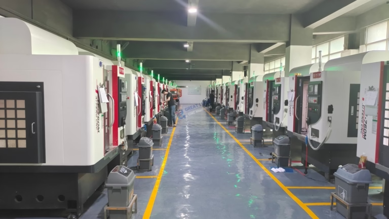
GreatLight has run this pattern since 2011 across three plants and 127 CNC machines, including 16 simultaneous 5-axis centers. The work is mostly aluminum and steel inserts, plus plastic parts where the tool is cut rather than molded. The same sequence applies either way.
- 1Owner of the designCustomer keeps CAD and IP; supplier keeps the method.
- 2Primary outputFunctional parts for test, not a tool with a long life target.
- 3Primary riskGeometry that cannot be cut or released cleanly from the tool.
Start with DFM, not with a steel block
The process begins the moment a 3D model arrives. A useful DFM review is not a wall-thickness check. It predicts fill, weld-line location, sink and where the tool will need a slide or a lifter. For a machined insert, it predicts whether a corner radius can be reached with the available tool shank and whether an undercut needs a separate piece.
Two numbers drive most of the early decisions. Minimum internal radius should be at least one third of the cavity depth, or you pay for long reach tools and slow feed rates. Draft on molded faces should sit between 1° and 2° for most thermoplastics; below 1° you will scuff on ejection.
At GreatLight the DFM analysis and quotation come back within 12 hours, and production can start within 24 hours of approval. That speed only holds if the model is clean. Open surfaces, unsewn solids and mixed units are the usual reasons a first review stalls.
Fix the model before you send it. A half-hour of cleanup on your side saves a day on ours.
- 1Check radius to depthInternal radius ≥ one third of cavity depth.
- 2Check draft1°–2° on molded faces; more on textured walls.
- 3Check units and solidsOne unit system, watertight bodies, no stray surfaces.
Pick the material and the tooling route together
Material and route are one decision. For functional prototypes and bridge production under roughly 500 parts, cutting the part directly from aluminum or engineering plastic is usually faster and cheaper than building a mold. Above that quantity, a steel insert set starts to pay back.
For the tool itself, P20 and 718H cover most low-volume plastic work. For abrasive filled resins, glass-filled PA or PEEK, go to a hardened insert at 48–52 HRC. Aluminum inserts are fine for a few hundred shots of unfilled ABS or PC, and they cut in a fraction of the time.
On the part side, 6061-T6 and 7075 machine cleanly and hold ±0.005 mm well. 316L and 17-4PH move more during cutting, so rough, stress-relieve, then finish. Titanium TC4 needs slower surface speeds and more coolant; do not treat it like aluminum.
If the part will later be molded, cut the tool in the same material family you intend to mold. Shrinkage and flow behavior differ, and a tool cut for the wrong resin will not transfer.
- 1Under ~50 partsMachine the part directly, no tool.
- 250–500 partsAluminum or soft steel insert, or vacuum casting.
- 3Over 500 partsHardened steel insert set with a real cooling layout.
Set the machining strategy before the first cut
Roughing removes the bulk and locks in the stress state. Leave 0.3–0.5 mm on finishing faces for aluminum and 0.4–0.6 mm for stainless. Then let the part rest before finishing; a 12-hour gap on thin walls is cheap insurance against movement.
Finishing passes should be light and consistent. A 0.1–0.2 mm stepover with a 6 mm ball nose gives a predictable surface and lets you plan the finish. If the drawing calls for Ra 0.8–1.6 μm, plan a separate finishing operation rather than trying to get there in one pass.
Fixturing matters more than most people expect on a tool insert. Clamp on a face that will be machined away later, or use a soft jaw matched to the insert profile. Do not clamp across a finished sealing surface; you will dent it and see it in the first-article report.
For deep cavities, use a 5-axis center with a stubby tool and a tilted approach. Long reach tools chatter, and chatter shows up as a witness mark on the molded part.
- 1Roughing stock0.3–0.5 mm aluminum, 0.4–0.6 mm stainless.
- 2Finishing stepover0.1–0.2 mm with a 6 mm ball nose.
- 3Clamp locationOn a face that will be cut away, not on a seal face.
Fit, assemble and check the tool before you run it
A tool is not finished when the last insert comes off the machine. Insert fit should be a light press or a close sliding fit, typically 0.01–0.02 mm clearance on locating faces. If a slide or lifter binds, it will gall within the first hundred cycles.
Check the parting line with blue or shim stock before you close the tool. A 0.02 mm shim should not pass on a sealing face. Any gap shows up as flash, and flash on a cosmetic part is a reject.
For molded work, run a short sample and measure the first parts against the critical dimensions. For machined tooling, run a first-article inspection on the insert and on the parts it produces. At GreatLight inspection runs at 100% before shipment, with raw material check, in-process monitoring and a final report on request.
Write the process window down. Injection pressure, hold time, mold temperature, coolant flow. A tool that only runs at one setting is not production-ready.
- 1Insert fit0.01–0.02 mm on locating faces.
- 2Parting line0.02 mm shim must not pass on a seal face.
- 3Record the windowPressure, hold, temperature, coolant flow.
When rapid tooling is the wrong choice
Rapid tooling is a bridge, not a destination. If the part geometry needs a 0.3 mm rib, a 0.05 mm texture or a 3° undercut on every wall, the tool will cost close to a conventional one and take nearly as long. Say so early and pick a different route.
Thin walls under 0.8 mm are a common failure point. They cool unevenly, warp, and force the tool to run at a narrow window. If the design needs that wall, plan for a longer cycle and a slower ramp.
Optical parts are another boundary. If the surface has to read as a class A finish, the tool needs polishing by hand, and that work does not compress into a two-day tool build.
Finally, if the annual volume is known and stable, build the production tool now and skip the bridge. Two builds cost more than one.
- 1Fine textureHand polish time kills the schedule advantage.
- 2Walls under 0.8 mmWarp and narrow process windows.
- 3Stable high volumeGo straight to the production tool.
Step-by-step process on the floor
Seven stages, in order. Skipping stage 2 or 6 is where most jobs go wrong.
- 11. Receive CAD and run DFMCheck solids, units and draft. Flag internal radii under one third of depth, undercuts and textured faces. Return a written DFM note with the quote, within 12 hours.
- 22. Lock the datum and fixture planChoose the datum from a functional face, not a convenient one. Pick the clamp location on a face that will be machined later. Write the fixture plan down before cutting.
- 33. Select material and routeP20 or 718H for standard plastic work, 48–52 HRC inserts for filled resins. 6061-T6 or 7075 for machined parts. Confirm the route against the planned quantity.
- 44. Rough, rest, finishLeave 0.3–0.5 mm on aluminum and 0.4–0.6 mm on stainless. Rest 12 hours on thin walls. Finish with 0.1–0.2 mm stepover to reach Ra 0.8–1.6 μm.
- 55. Cut critical features on 5-axisUse a stubby tool and a tilted approach on deep cavities. Hold ±0.005 mm on locating features. Keep the tool overhang under 4× diameter.
- 66. Fit inserts and check the parting lineTarget 0.01–0.02 mm on locating faces. Blue or shim the seal face; a 0.02 mm shim must not pass. Fix galling before the first run.
- 77. Sample, inspect, documentRun a short sample, measure critical dimensions, record the process window. Ship with first-article data and the inspection report attached.
Which rapid route fits your quantity and geometry
Use this as a first filter. Final choice follows the DFM note.
| Route | Typical quantity | Best geometry | Watch out for |
|---|---|---|---|
| Direct CNC part | 1–50 | Tight tolerance, thick walls | Cost per part stays high |
| Aluminum insert tool | 50–500 | Simple, shallow, unfilled resin | Low shot life, soft edges |
| Hardened steel insert | 500+ | Filled resin, long runs | Longer lead time, higher cost |
| Vacuum casting | 10–100 | Fine texture, cosmetic surfaces | Silicone mold wears fast |
| Sheet metal | 1–10,000+ | Flat parts, bends, enclosures | Not for complex 3D shapes |
The process is only as fast as its slowest stage
Send a clean model and lock the datum early. Most schedule loss happens before the first cut, not at the machine. If quantity is stable and high, skip the bridge and build the production tool.
Questions engineers ask before a tool build
How long does the ODM rapid tooling fabrication process take?
DFM analysis and quotation come back within 12 hours, and production can start within 24 hours of approval. Machined parts typically ship in 3–5 days.
A tool build runs longer than that. The schedule depends on cavity depth, the number of slides, and whether the design is frozen. Freeze the CAD before you commit to a date.
Can you hold ±0.005 mm on a tool insert?
Yes, on locating features and critical dimensions, when the geometry allows a stiff setup. Long reach features and thin walls move more, so we quote those separately.
We inspect 100% before shipment, with raw material, in-process and final checks.
What is the minimum order quantity?
There is no minimum. We run from one prototype to 10,000+ part runs.
For a single part, machining it directly is usually cheaper than building a tool. We will say so in the DFM note.
Which materials do you cut for tooling?
P20, 718H, tool steel at 48–52 HRC, plus aluminum inserts in 6061, 7075 and ADC12.
For direct parts we run stainless 303, 304, 316L, 17-4PH, titanium TC4, Inconel, and engineering plastics including PEEK and glass-filled PA.
How do you protect our design?
Uploads are secure and confidential. An NDA is available on request, and we hold ISO 27001:2022 for information security.
We do not share customer files outside the project team.
What certifications cover this work?
ISO 9001:2015, IATF 16949:2016, ISO 13485:2016 and ISO 27001:2022.
Inspection reports are available on request with each shipment.
Send your CAD and get a DFM note back within 12 hours
Upload the model, tell us the target quantity and material, and we return a written DFM review with a quote. No minimum order, and uploads stay confidential.
12-hour DFM + quoteProduction in 24 hours100% inspectionNo MOQ
More from GreatLight
We publish setup notes, tooling trials and inspection data from the factory floor.











