Parts can take three different paths before being injection molded:Some parts come first3DPrint and make prototypes, yesManufacturability considerations for injection molding are limited. Others take more traditional machining routes,Generally better in terms of manufacturability becauseCNCThe design requirements for machining and injection molding are similar, if not identical, and many others have not undergone prototype iteration testing.Go straight to injection molding.
Before production begins, there are some important design elements to consider that can improve the manufacturability (plasticity) of the part and reduce the chance of surprises, cosmetic defects, and other issues that may arise during production.
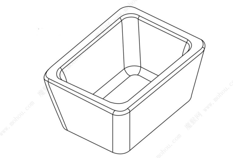
1.Draft angle
Injection molded parts must be removed from the mold after injection molding is completed. However, without proper design, it will be difficult to remove the parts. For example, if a part has deep, straight walls, it will easily stick to the mold as the material cools and shrinks against the mold core, making it difficult to remove. The ice cube box used to freeze ice cubes in our daily life is also a kind of mold. If you look closely, you will find that the frozen ice cubes are not really straight up and down ice cubes, but have a slight up and down angle. at the bottom, with the top slightly larger, slightly smaller on the smaller side. If it is a straight top to bottom design, it will be difficult for us to remove the ice cubes from the ice cube tray. In the same way, if we want the injection molded parts to be removed from the mold smoothly, we need to give them a tapered angle on the side, which we call draft angle or undercut angle.
The draft angle isCNCSimilar concepts exist in machining, but are more important for injection molding,A limited draft angle can place excessive stress on the injection system, potentially causing part damage or even damage to the mold. Especially for parts that want to use a stripping pin to automatically strip, the draft angle is even more necessary.

Figure: An example of a draft angle
There is no fixed value for draft angle, which is determined by factors such as the specific part material, surface finish, part depth, etc. A part with a smooth surface requires a smaller draft angle than a part with a heavily textured surface.a comparisonA good rule of thumb is every 1 inchofCorresponding depth of mold cavity1degree of draftslopebut it is not absolute. At Mohou, we will perform a detailed analysis and review of each part feature to predict which parts require increased draft angle for protrusion.
2.chamfer
Chamfering is not a necessary condition for injection molding;But we should use chamfers in some parts as much as possible to eliminatesharp corners on parts This will improve material flow and part integrity。
Plastic filled in mold cavity exhibits curvatureThe corners flow better, like the flow of a river. The river does not90degrees of corners, because the flow of water creates internal and external corners, so it is easy to move towardsdownstream final destination flow. Likewise, molten plastic wants to take the path of least resistance to minimize stress on the material and mold. Similar to draft, chamfers also make parts easier to unmold because fillets reduce the risk of the part getting stuck in the mold, causing it to warp or even break.

Figure: Sharp corners have high stress concentrations and plastic flow is impeded. Chamfering reduces stress concentrations and improves plastic flow.
3.wall thickness
Controlling wall thickness during part design helps manage the aesthetics, weight and strength of the part. Parts that are too thick can cause unsightly dents, warping, and internal voids (air pockets). In order to avoid this situation, our magic monkey has summarized a recommended wall thickness for different materials.–But this is only a general rule, because not all parts are suitable for the wall thicknesses recommended in the table. Also,The connection between two different wall thicknesses must have an arc or slope transition.which promotes the fluidity of the plastic resin in the mold cavity and reduces the stress concentration of the finished product (as shown in the figure)

Figure: There should be a slope transition at the connection of different wall thicknesses
Table: Recommended thicknesses for different plastics
Material | Recommended wall thickness(MM) |
ABS | 1-3.5 |
P.O.M.(polyoxymethylene) | 0.75-3 |
PMMA(acrylic plexiglass) | 0.6-13 |
Liquid crystal resin | 0.75-3 |
long fiber reinforced plastic | 2-25 |
nylon | 0.75-3 |
PC | 1-4 |
Polyester | 0.6-3.2 |
PE | 0.75-5 |
P.P.S. | 0.5-4.5 |
PP | 0.6-4 |
P.S. | 0.9-3.8 |
Central unit | 2-19 |
4. Lose weight and strengthen your muscles
In addition to using appropriate wall thickness, other factors must be considered to ensure the design integrity of the part. One might think,The thicker the part, the stronger it is—This is a false assumption. A properly designed structural part should contain stiffeners and sandwich ribs, which add strength and help eliminate cosmetic defects such as warps, dents and voids.
For thicker part sections, by reducing weight and using appropriate stiffeners, you will have the ability to maintain the height and overall diameter of your part without necessarily sacrificing performance, and will also most likely improve performance and length. appearance of the room.
The general rule for stiffener thickness is to use the thickness of the adjacent surfaces.40%has60%As shown in the figure, the ratio of the wall thickness of the part to the thickness of the ribs supporting it is approximately2:1which helps prevent thick parts from cooling at different rates than thin parts. It also helps reduce settlement and stress, which can cause warping in your parts.

Figure: The thickness of the stiffener should be approximately half the thickness of the wall
Mezzanine railings and ribs are another design element that strengthens and enhances the appearance of the room. Likewise, plastic fluids prefer smooth transitions between geometric shapes, and a small slope helps the material slide between different levels. Sandwich triangles help support a wall or feature while reducing molding stress.
5. Core and cavity design
The core and cavity are often called theAMenwaBTop and bottom face or halves, using core–A cavity approach to part design can save time and money during manufacturing and improve the overall appearance of the part. Let’s say you are designing a simple box. If the moldAMenwaBIf you use the traditional method of stacking sides A and B directly, you will have a very deep groove, which is difficult to manufacture and increases the cost of the mold. In addition, the deep groove may cause insufficient filling (lack of material), difficulty in ejection and easy molding. Damage and other problems.
through the core–The cavity design helps minimize all of these problems. This design technique requires the exterior and interior walls to be designed parallel to each other with the same draft angle. This approach maintains a constant wall thickness, maintains part integrity, increases strength and plasticity, and reduces overall manufacturing costs.

Image: traditional design: The walls of the box will become deep grooves, and the cost of machining and polishing the walls is higher. Central cavity method. Box designed by central cavity method. Features can be handled with bigger and faster tools. Polishing is easier and faster.
6.undermine
Injection moldingnecessary partsdesignThe simpler the better,Is this true? it’s a mistakeAnswer,becauseIn the magic monkey,We take care of the design of complex parts,includeneedunderminevias and other features.
outsolecuttreatmentYesrelativelySimple and profitablehigherthis is because we are driving the side through the pinSliding core moldComeaccomplish. The cam moves along an inclined pin when the mold is opened and closed. When open, the cam retracts fully to allow easy ejection of the part without damaging the mold, and closes until the cam is in position to make the next part.
unable toUse side slider coreIn this case we can use manually removed inserts. these arethe smallest1cubic centimetersMold parts, loaded by the operator before stopping the press. Once the part is formed, the part is ejected with the insert. The operator then collects the part, manually removes the insert and puts it back into the mold for the next part.

picture:The image on the left shows a clip with an undercut feature. In the right image, under the undercutopeningallowinsertInsertsMoldand provide the required latchesto change。
7.Door and ejector design
Gates and topsstemIt’s plastic resineffectiveNecessary for smooth entry into the mold and efficient ejection of plastic parts from the mold. Before we prepare to make molds, we should considerDoor and ejectorLocation.
The most commonly used is the sheet metal gate because it is the moldengineersProvides optimal processing capabilities and the ability to increase size when the process requires it.FlakyThe size of the gate gradually decreases from the slider so that the smallest point is on the surface of the part. This creates a freezing point between the part and the channel, which removes heat from the surface of the part.,to minimize the risk of dents in the part. After molding, the label door must be removed manually, leaving0.15Door residue in mm. Underdoors are usually placed on the side or top of the room.stem(rear door) is used by adding a tunnel door. Both injection methods generally reduce the size of the residue left outside the part. Tunnel doors still enter the room from the outside, but are centered on the surface of the room, so they generally leave fewer door marks. Pillar doors leave no visible marks outside the room because the room passes through a roof close to the perimeter of the room.stemTo be completed. The risk is the appearance of a shadow on the other side of the room due to the heat and the thickness of the room. Therefore, on textured or highly polished heightsAppearance requiredBe careful when using this method with coins.
The Hot Head Door EffectAlsoveryGOODas they result in minimal waste of parts for gate and slide systems. Thermal doors are ideal for rooms that require even filling from the center to the outer edge.,heAny movement of the mold can be minimized becauseFlakyGates can create unbalanced pressures in the mold. Hot tip gates are generally the most aesthetically pleasing gates (diameter approx.1.27mm) and can often be hidden in niches or around logos or text.
The direct door is the leastEasy to usethe direct gate has a large diameter and is difficult to remove manually. In many cases it is necessary to remove the luminaire by milling.Generally onlyUsed for specific materials with high glass content or where secondary processing is required in the middle of parts.
Daguang focuses on providing solutions such as precision CNC machining services (3-axis, 4-axis, 5-axis machining), CNC milling, 3D printing and rapid prototyping services.


