1. Pneumatic system
(1) The pneumatic system includes triple combination, solenoid valve, throttle valve, muffler, cylinder, etc. This device mainly supplies air to the tool drive cylinder above the spindle, the spindle blower and the tool magazine pneumatic cylinder. (Note: the image below is a triple combination)
(2) The left side is the air pressure detection meter. When adjusting the air pressure, please gently pull the air pressure adjustment knob upwards and then turn it clockwise. When the pointer exceeds the 0.6 reading position indicated on the air pressure meter. when the air pressure reaches the required air pressure. (Note that the pressure increases when the adjustment valve is turned clockwise and the pressure decreases counterclockwise. After adjusting the air pressure, lightly press on the adjustment knob Remember not to set the pressure too high, otherwise it will damage the components).
(3) On the right side is the air pressure sensing switch. This detection switch was set before leaving the factory and does not need to be adjusted. The position indicated by the pointer indicates that an abnormal alarm will occur when the inlet pressure is reached. lower than this pressure. If adjustment is needed, please use a flat blade screwdriver to turn the adjustment screw located on the top of the case.
(4) Normal pressure should be kept at 6-8 kg/cm2. If there are too many machines in the user’s factory that need to use air, it is recommended to install an air tank air and a check valve next to the machine. the air pressure should not be less than 6 kgf/cm2, otherwise the machine will stop immediately and an abnormal signal will be displayed on the screen.
(5) When the air compressor is not drained for a long time, water will enter the machine with the hose. When the booster filter device is filled with water, it is automatically discharged when the machine stops working. the steam inside can also be vented manually. Failure to drain the water will damage the pressurized air circulation system. (When manually draining, manually turn the knob on the bottom of the pressure relief filter to drain)
(6) When air enters the oil mist lubricator, it removes a small amount of oil. This oil can lubricate all sliding components to extend the life of components. This lubrication will reach the cylinder, solenoid valve and air pressure lock knife. , Spindle positioning, ATC mechanism. The amount of oil in the oil cup should not be too large, lest the air flow is too low and the nozzle flow is not enough to create a vacuum, so that the lubricating oil cannot be sucked out of the container. (Try to use pressure and wear resistant ISOVG32# hydraulic oil or VG20# spindle oil)
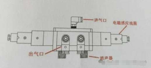
2. Solenoid valve
(1) The directional control valve provides the most basic loop control method, which can switch the fluid path or change the flow direction according to the action program requirements, and can control the start, stop, direction of movement of the actuator, etc.
(2) The breakdown is generally due to dust: this is the main cause of the breakdown. It is usually introduced through dirty external air intake pipes. Dust and other dust are mixed in the induction coil of the solenoid valve, resulting in poor contact and rust. or cylinder malfunction. Inappropriate lubricating oil: caused by the use of engine oil and other lubricating oils with too high viscosity.
(3) In case of malfunction, please check whether the oil in the oil storage container meets the requirements. At the same time, you should regularly check whether the company’s air compressor drains water and whether the filter element in the combined pressure of air pressure. The backup filter is clogged.
(4) Muffler: installed at the exhaust port to reduce the noise of gas leakage.
3. Lubrication system
The three-axis guide rails and ball screws of this machine are powered by an automatic lubrication device. When the automatic oiler works, the oil will be sent to the oil distributor (Oildistributor) of each axis via the oil outlet. The distributor will evenly distribute the oil to the guide rail, ball screw and bearings at both ends of the ball screw. for lubrication (so if oil is required, try to use wear-resistant ISOVG68# guide rail oil or equivalent type guide rail oil).
(1) Oil injector is a combination of timer, pump, liquid level detection device, oil tank and lubricating oil. It supplies lubricating oil and distributes it to the distributor (distributor) through pipelines. mechanical sliding surface and rotating mechanism. Pay attention to whether the oil is the guide oil used, otherwise the oil pump cannot pump the oil, which may damage the oil pump during load operation for a long time.

(2) When the quantity of oil in the tank is insufficient, or the pressure cannot be detected, or the oil pipe is broken, etc., the internal detection device will output a signal on the screen NC and an abnormal alarm (LUBEALARM) will appear on the screen. At this time, the buzzer is located on the left side of the oil injector. The buzzer will emit a high-pitched beep and the LUBE button on the control panel will illuminate to inform the operator that an alarm has been triggered. occurred.
(3) When the lubricator is damaged, you should contact the machine manufacturer to replace it, otherwise the machine will lack oil for a long time, resulting in wear and deformation of guide rails, ball screws , etc.
(4) Description of the action of the automatic lubricator:
There are two timers on the front of the automatic lubricator. They can adjust the action time and oil outlet time. The timer on the right allows you to set the action time. This scale is calculated in minutes. The left timer allows you to set the refueling time. This scale is calculated in seconds. Before the machine tool left the factory, we set the right timer to 30 minutes and the left timer to 15 seconds. The output pressure of each oil injection is 1.5kg/cm’, these two times are optimal, please do not adjust them arbitrarily. (Note: There is an oil key button right in front of the oiler. When this button is pressed, the oiler is forced to operate and produce oil. If you think there is a problem with the oiler, you can press this button and observe whether there is oil in the transparent oil pipe.
4. Electrical box heat exchanger
After long-term use, the electrical box cooling device will produce vibration, noise or accumulation of oil and dirt. In order to maintain the cooling efficiency of the electrical enclosure, a certain flow of cold air must be maintained. the exchanger will let outside air pass. The filter is sent to the electrical box, so the filter should be cleaned regularly every week to avoid clogging and reduce cooling efficiency. In order to achieve operating efficiency, although this heat exchanger is powered by a fan only, maintenance work has been kept to a minimum, so regular maintenance is necessary. (Note: the heat exchanger is located on the electrical box door)

5. Cutting pump/water tank
(1) Check the oil/water volume of the cutting fluid every week. The water tank should be kept at around 2/3 full. The current cutting fluid/oil volume can be seen on the fluid level gauge located on the edge of the cutting fluid water tank. .
(2) Clean the chip flute regularly. For example, the chips produced by drilling will be relatively long. Compared to the fine chips produced by milling, long chips require more frequent cleaning.
(3) The cutting fluid water tank should be cleaned at regular intervals. The duration of the interval depends on the use of the machine and the material to be processed. Dirt deposits will usually occur over a long period of time. cleaned about once a month. Thrown away. Please handle the cutting oil according to specifications. (4) The pump works for a long time in a high temperature or humid environment and is affected by the customer’s environment. This could damage the pump or cause abnormal conditions. Check the pump weekly for abnormal noises, low water flow, abnormal overload alarms, etc.
(5) Turn off the power, disconnect the quick connector between the pump and the electrical box, check whether oil or water has entered the pump junction box or the pipeline is damaged, remove the water tank pump and check if the filter is blocked. If so, please clean up in time.
6. Spindle oil cooler
In order to maintain the cooling efficiency of the spindle oil cooler, a fixed air flow must be maintained. Regular cleaning of the air filter is therefore very important. A clogged air filter will cause insufficient air flow and the machine to overheat. The regular cleaning schedule has different cycles depending on different factory processing environments. Dustier locations require more frequent cleaning of the filter. Generally speaking, the filter should be cleaned at least once a week. (Note: Please use ISOVG32# anti-wear hydraulic oil. Adding other oils will damage the spindle.)

7. Spindle cutting cylinder
When the machine tool is equipped with a tool magazine, the tool cylinder is used to provide the necessary power to the spindle to loosen the clamped tool during the tool changing process. When the cutting cylinder performs the clamping action, the air pipe carries a small amount of oil, which can lubricate all sliding components to extend the life of the components. (Note: The cutting cylinder is installed on the spindle head, and the upper sheet metal cover of the head must be opened when refueling.)
(1) Do not add too much oil each time into the lubricating oil cup, and maintain 2/3 of the oil volume. (Please add ISOVG32# anti-wear hydraulic oil or similar type oil)
(2) Stroke switch: It ensures that the tightening and loosening signal can be quickly detected when the tool cylinder moves, ensuring that no abnormal alarm will occur when changing tools.
(3) The spindle cannot loosen or tighten the tool.
Reasons: 1. The adjustment screw at the end of the cutting cylinder is loose. 2. The stroke switch located next to the cutting reel is loose or damaged. 3. The solenoid valve controlling the cutting cylinder is damaged.
Countermeasures: 1. Check whether there is oil in the oil bottle on the right side of the knife cylinder. 2. Readjust the screw to the appropriate position. 3. Use the manual movement of the cutting cylinder, readjust and fix the contact switch or replace the contact switch. 4. Replace the solenoid valve.
(4) The loosening and tightening devices have been tested before leaving the factory. Users are not allowed to disassemble or adjust this device without authorization if there is no defect.

Daguang focuses on providing solutions such as precision CNC machining services (3-axis, 4-axis, 5-axis machining), CNC milling, 3D printing and rapid prototyping services.


