The cylinder head is installed above the cylinder block, sealing the cylinder from above and forming the combustion chamber. It is often in contact with gases at high temperatures and high pressures, which allows it to withstand heavy thermal and mechanical loads. A water-cooled engine has a cooling water jacket inside the cylinder head, and the cooling water hole at the lower end of the cylinder head is connected to the cooling water hole in the block -cylinders. Use circulating water to cool high temperature parts such as the combustion chamber.
The cylinder head is also equipped with intake and exhaust valve seats and valve guide holes for installing intake and exhaust valves, as well as intake and exhaust runners. The cylinder head of a gasoline engine is machined with a hole for installing a spark plug, while the cylinder head of a diesel engine is machined with a hole for installing a fuel injector. The cylinder head of an overhead camshaft engine is also machined with a camshaft bearing hole to install the camshaft.
The cylinder head is generally made of gray cast iron or alloy cast iron. Aluminum alloy has good thermal conductivity, which is beneficial for improving the compression ratio.
The cylinder head is an integral part of the combustion chamber. The shape of the combustion chamber has a great influence on the operation of the engine. Due to the different combustion modes of gasoline engines and diesel engines, the parts that make up the cylinder head. in the combustion chamber are very different. The combustion chamber of a gasoline engine is located primarily in the cylinder head, while the combustion chamber of a diesel engine is located primarily in the pit at the top of the piston.
1
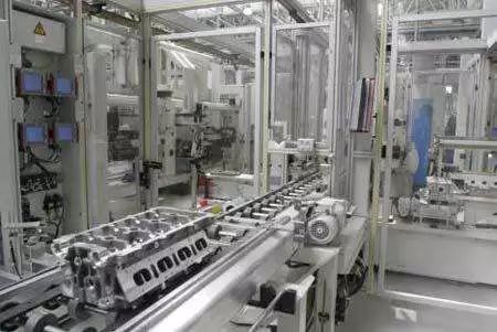
Production line layout
Engine cylinder head processing mainly uses flexible production lines. The production equipment mainly consists of machining centers, equipped with a small number of specialized machine tools providing flexibility and necessary auxiliary machines. The equipment is connected by conveyor rollers. From the perspective of flexibility, most of the processing content is completed by a vertical machining center. For some processing contents, a fourth rotary axis needs to be purchased in the vertical machining center. Compared with choosing a horizontal machining center, it not only meets the processing requirements, but also reduces equipment expenses.
The process flow of flexible processing lines is generally divided into: decentralized process type and centralized process type.
Type of decentralized process:
In a production line where processes are dispersed at the same time, processed parts must pass through all processing equipment before they can be processed. If one of the processing equipment breaks down, the entire production line will be shut down.
Type of centralized process:
The same machining center model should be used as much as possible on the processing line, and different process contents should be concentrated on a single machine tool to process the workpiece efficiently with the least clamping time. When processing equipment fails, the same type of equipment in the same process can be used to continue production. Although the production volume is reduced, the shutdown of the entire production line can be avoided. The centralized process can also be used to increase or decrease production or switch to processing equipment. Switching to equipment can avoid wear and tear on the machine tool during repeated use under fixed working conditions. On the contrary, the disadvantages are: poor part tracking ability, which is also the case. The parts processed by the equipment are not easy to trace, and the rotation of tools during production is relatively large.
2
Reference selection

Coarse data selection:
The raw data mainly considers the sufficient margin of each processed surface, and the size and position of the unprocessed surface are combined with the drawing requirements. To ensure the position of the cylinder seal surface and the rough surface in the combustion chamber, it is indeed necessary to choose a reasonable rough mark. There will be three steps of positioning the process in the direction of the cylinder seal surface of the cylinder head. For rough reference, this positioning step of the process is located in the same direction as the combustion chamber and is formed from the same profile of the casting mold. . There is no separation or other molding. The process error is relatively accurate, so the rough reference in the cylinder seal surface direction of the cylinder head should be used as the first positioning data to process the fine data for machining. Subsequent errors are all accumulated errors caused by repeated positioning using a machined precision reference. They are relatively weak and will not affect the compression ratio.
Fine selection of benchmarks:
Mainly considering the principles of “data coincidence” and “data unification”, in mass production, the reference generally uses the ground and two pinholes. The joint surface of the cylinder block and the joint surface of the cylinder head cover are relatively large and structurally matched to a fine reference. Therefore, the joint surface of the cylinder block and the two locating pin holes on this surface are selected as the first fine data of the cover. the joint surface constitutes the second reference point.
Briefly describe the process journey:

3
main processing location
Aircraft processing
The upper surface, lower surface and intake/exhaust surface of the cylinder head are all large-area flat surfaces with high precision requirements (flatness, verticality, positioning, etc.). This requires relatively high geometric precision of the machining center and tool setting precision.
As an automatic machine tool that eliminates human intervention during processing, the geometric precision control of the machining center must truly meet the requirements of smoothness of the movement trajectory of the tool tip forming the surface of contour of the part in relation to the part in its work area. Therefore, the inspection should focus on the accuracy of shape and position which affects the processing of the part.
The bottom of the cylinder head and the mating surface of the cylinder block, together with the piston, form the combustion chamber of the engine. The cylinder head resists the effects of gas and bolt pre-tightening force at high temperatures and high pressures. engine operation. Therefore, the bottom surface of the cylinder head is generally selected as a rough reference for surface treatment. According to this reference point, the position of the upper surface, sand outlet and airway plane is checked.
Cylinder Block Gasket Surface: Generally, the cylinder head combustion chamber is a blank surface and does not require machining. Therefore, the position accuracy requirements for the cylinder seal surface and the blank surface in the combustion chamber are relatively strict. In addition, this surface is closely linked to the sealing of the engine’s combustion chamber. Although there is a cylinder seal between the cylinder block and the cylinder head, the flatness of this surface must nevertheless be relatively high.
The cover surface matches the cam cover, which mainly plays the role of dustproof and noiseproof. There is also a cylinder seal in the middle. The intake/exhaust corresponds to the intake/exhaust manifold respectively. There are joints in the middle. some controllers are mainly installed on both sides and covers and other devices. These parts should be lower than the cylinder seal surface.
High precision hole processing
The valve seat, guide hole, tappet hole and camshaft hole system on the cylinder head have a matching relationship, and their requirements for dimensional accuracy, position accuracy and roughness of surface are extremely strict.
The function of the cylinder head requires that the valve seat hole after treatment and the untreated air passage have relatively precise position requirements to ensure that the cylinder head has a good gas distribution function under working conditions. Therefore, the rough reference for hole processing in general. selects the valve hole, checks the shape of the lower surface and the position of the strap according to the valve hole, draws the transverse center line of the lower surface, and leads to the upper surface.

1. Finishing of cylinder head valve seat and valve guide

Above: Valve seat and valve guide Bottom hole – finish
The cylinder head valve seat and valve guide cooperate with the engine valve at the same time, so the coaxiality requirements are relatively high. In addition, the sealing cooperation between the valve seat and the valve cone surface is also very high.
Positioning and processing the valve guide and the valve seat at the same time can reduce repeated positioning errors and improve the coaxiality of the valve guide and the valve seat.
When processing the valve seat, the cutting direction should be in the radial direction of the valve seat. This processing method is to “rotate” the valve seat, which can ensure processing accuracy. If the feed direction is in the axial direction of the valve seat, it becomes “milling” or “boring” of the valve seat.
2. Processing of cylinder head lift holes and valve guide lower holes

Above: Rough machining of the tappet hole

Above: Finishing the pusher hole
The valve lifter is assembled to drive the intake and exhaust valves with the power transmitted through the camshaft. There is a certain requirement for coaxiality between the tappet hole and the guide hole. But as long as the machining allowance, parameters and tools are selected, there is basically no problem in the machining process.

3. Cylinder head camshaft hole processing
A camshaft is installed in each of the intake and exhaust camshaft holes, and the camshaft rotates in the hole to drive the lifter. Therefore, the coaxiality of the camshaft holes in each gear is very high, otherwise early wear and camshaft jamming will occur. occur, or even unable to assemble and other problems.
The cylinder head camshaft hole is the longest hole of the cylinder head, if processed in sections, although the machining accuracy of the camshaft hole can be guaranteed, it cannot meet to the coaxiality requirements of the camshaft hole, so it only requires one time. finishing the treatment. For a tool holder with a length of about 500 mm, how can the influence of its own gravity be eliminated?
For automatic special machine lines, they are usually equipped with boring die frames to eliminate impact. For larger engines, there may be multiple bore die frames.
For machining centers, the boring die frame has been virtually eliminated and tool autoguidance is used to eliminate the influence of tool holder gravity. The structural characteristics of the tool holder are as follows: one blade and three guide strips are evenly arranged. arranged around the circumference of the tool holder. The number of toolbars is usually one long and one short.
4.Others
There is no close connection between the spark plug hole, spiral hole, threaded hole, water hole and oil hole and other components, and the location requirements are not are not high.
Summary:
The positional relationship between the stop holes of the camshaft hole system is particularly important.
The positional relationship between the valve seat guide hole system is particularly important.
The positional relationship between the cylinder seal surface and the blank surface in the combustion chamber is important.
The positional relationship between the tappet hole and the guide hole is important.
The position accuracy requirements for the remaining parts are average.
Other treatments
The distance between the cover surface and the cylinder seal surface does not need to be too strict. From the assembly point of view, the cover surface is assembled with a cover and does not have much relationship with other parts, so the position requirements of the cover surface do not need to be determined. ‘be too strict. In fact, the reason for this problem is that the cover surface and the center line of the camshaft hole are often located on the same plane, causing confusion between these two dimensions. There are requirements for the distance between the camshaft hole and the cylinder block mating surface, which is generally ±0.005mm. This is because in the valve mechanism, there are certain position requirements between the valve seat and the camshaft hole system, as well as the distance. between the two The distance affects parameters such as valve stroke and valve clearance, so it is larger, but it does not reach the single tightening level. The cylinder block joint surface is the process benchmark for Jiangrong’s camshaft hole and valve seat hole. Therefore, both have a requirement for the mating surface of the cylinder block.
In mass production, especially when there are many sub-sequences, there are a lot of movements between processes, which can easily cause too many parts collisions and affect product quality. In this regard, in addition to strengthening management, in terms of technology, we must do our best to eliminate important items, especially bumps and bruises. In this regard, in addition to strengthening management, in terms of technology, important parts, especially collision-prone parts, should be placed at the end of the production line for finishing processing. For example, the cylinder body and the seal surface. are very important for assembly. During processing, this is an important process reference and should be used for positioning. Additionally, the assembly process of parts such as conduits, valve seats and cable glands must be completed before finishing, which can cause surface damage. bumps. Therefore, in order to prevent this type of phenomenon from occurring, it is preferable to leave a small machining allowance on this surface at the start of the line and to carry out a finishing treatment at the end of the line, thus guaranteeing the better appearance quality. extent.
4
Specific layout of the process path
Cylinder head process route
AF10 loading, blank visual inspection and marking
Drilling and milling of intake and exhaust surfaces AF20
AF30-1 combustion chamber and front and rear drilling and milling
AF30-2 Drilling and milling of the control surface and the outlet surface of the combustion chamber
AF40 drilling and milling of roofing surfaces
AF50 valve seat guide bottom hole processing
AF60 medium cleaning
AF70 Seal Leak Test
AF80 valve seat guide, interference fit
AF90 precision milled combustion chamber surface
AF100 precision milling cover surface treatment injector hole
AF110 Valve Seat Guide and Hydraulic Lifter Hole Finisher
AF120 cover assembly
AF130 Precision Bore Hinge Cam Bearing Bore
AF140 Finishing Control Surface
AF150 Removing the cylinder head cover
Final cleaning AF160
AF170 cooler
AF180 Steel Ball Water Plug and Leak Test
The AF190 rolls off the production line for final inspection
5
Frequently asked questions during treatment
5.1 Mode of stomatal failure
Cause: A large amount of gas is generated in the casting mold cavity during the casting process of the casting blank, and casting defects are caused by poor exhaust in the casting system.
5.2 Camshaft hole roundness
Cause:
① The processing allocation left in the previous process is insufficient.
② The processing coordinates of the previous process are shifted.
③ The positioning surface of the luminaire is uneven (cuts or impurities).
④ The coordinate dimensions of the previous process and the next process do not coincide.
5.3 Scratches on the treated surface
Cause:
① Parts are produced during transportation.
② The clamp auxiliary positioning block has burrs or interference.
③ Caused by improper operation of hand tools during manual deburring.
5.4 Crushing on the treated surface
Cause:
① When the cutting machine tool clamps the workpiece, the positioning surface of the device is not cleaned cleanly, and the chip residue may crush the workpiece.
② During cleaning, chips remain in the water channel of the workpiece, causing the workpiece to be crushed when the pipe and seat are pressed.
5.5 Crack rupture mode
Cause:
① Caused by external force.
② Thermal stress generated during the casting process.
Seat ring is not depressed
Cause:
① There are impurities in the bottom hole of the seat ring.
② When the seat ring is pressed, the seat ring and the pressing head are not placed correctly.
③ The pressure of the machine tool is insufficient.
④ The outer diameter of the seat ring is large or the hole of the cylinder head seat ring is small and the interference is large, resulting in insufficient interference fit.
5.6 Treatment of valve belts
Cause:
① Tool adjustment fails.
② The specified feed depth setting is invalid.
③ Tool mode causes rough overshoot to fail.
Daguang focuses on providing solutions such as precision CNC machining services (3-axis, 4-axis, 5-axis machining), CNC milling, 3D printing and rapid prototyping services.


