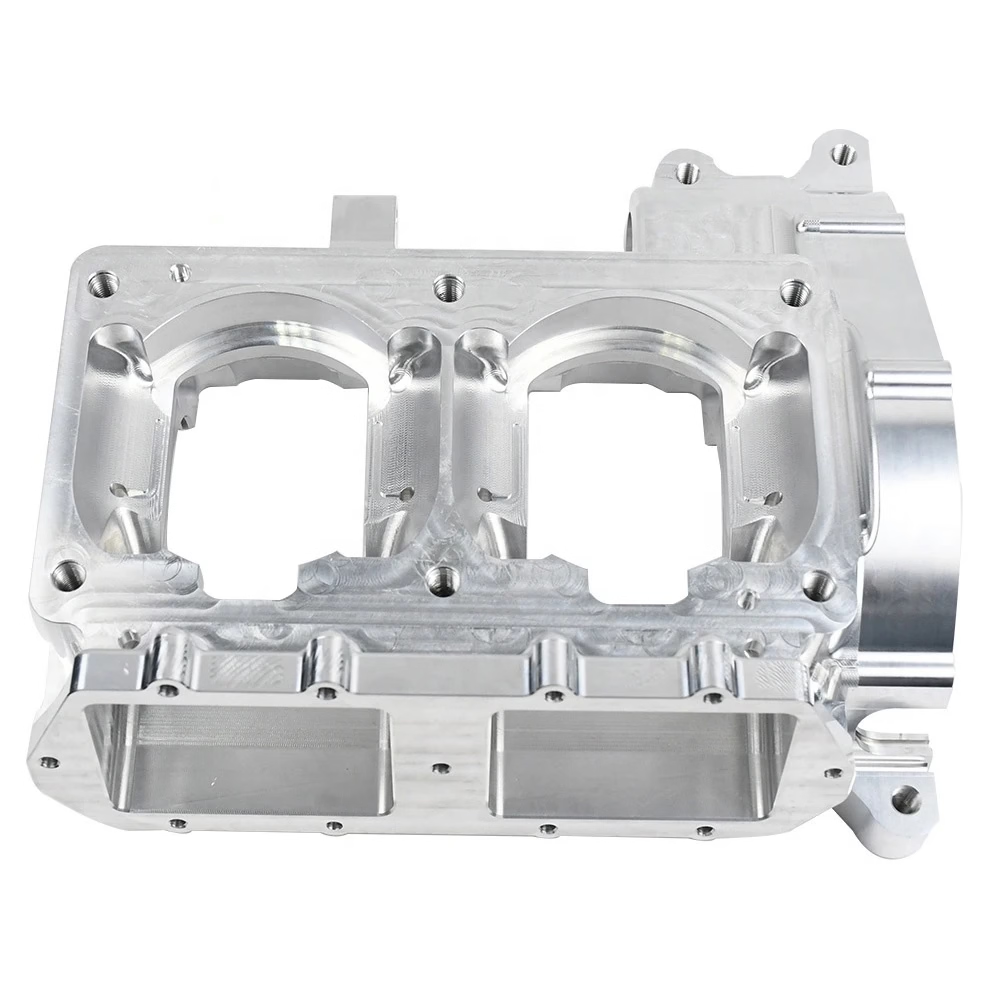
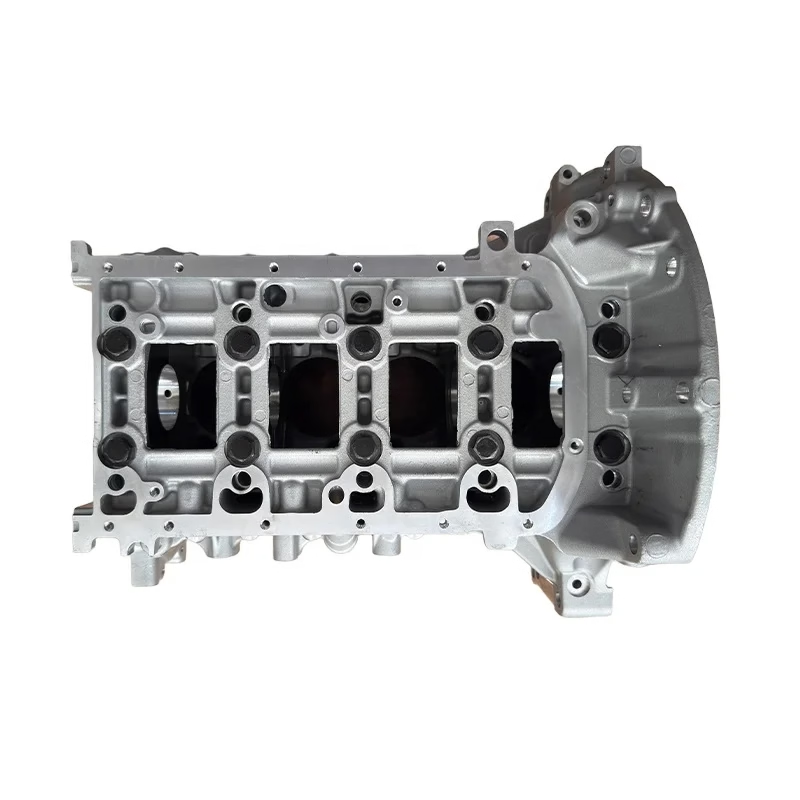
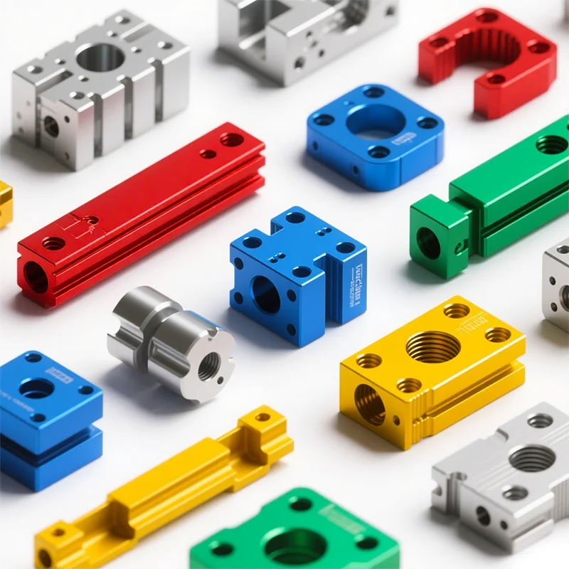
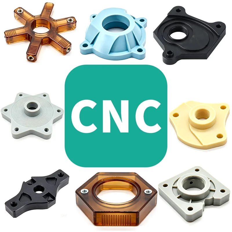
The machining center integrates oil, gas, electricity and CNC. It can clamp all kinds of complex parts such as discs, plates, shells, cams, molds and other parts at the same time, and can carry out drilling, milling, reaming, expanding, the bore. , etc. It can handle various processes such as rigid tapping, so it is ideal equipment for high-precision machining. This article will share the skills of using the machining center in the following aspects.
How to adjust the tool in the machining center?
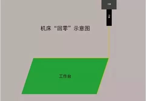
1. Return to zero (return to the origin of the machine tool)
Before adjusting the tool, be sure to perform a return-to-zero operation (return to the origin of the machine tool) to clear the coordinate data of the last operation. Note that the X, Y, and Z axes should all return to zero.
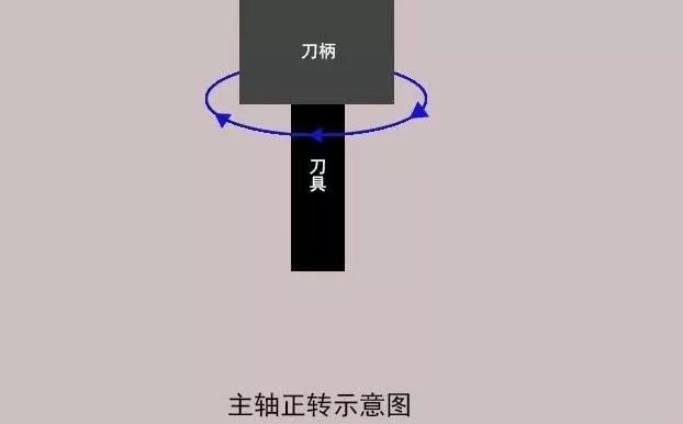
2. Spindle rotation forward
In “MDI” mode, enter the command code to rotate the spindle forward and maintain an average rotation speed. Then switch to “Handwheel” mode and activate the movement of the machine tool by changing the adjustment speed.
3.X steering tool adjustment
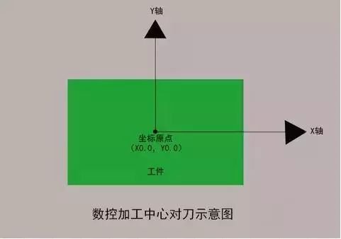
Use the tool to gently touch the right side of the workpiece to clear the relative coordinates of the machine tool; lift the tool in the Z direction, then move the tool to the left side of the workpiece and move the tool and workpiece down. Z at the same height as before. Touch lightly, lift the tool, note the X value of the relative coordinates of the machine tool, move the tool to half of the relative X coordinates, note the X value of the absolute coordinates of the machine tool, and press (ENTER ) to enter the coordinate system.
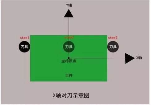
4. Y direction tool adjustment
Use the tool to gently touch the front of the workpiece to clear the relative coordinates of the machine tool; lift the tool in the Z direction, move the tool to the back of the workpiece, and move the tool and workpiece down along Z to the same height as before. Touch lightly, lift the tool, note the Y value of the relative coordinates of the machine tool, move the tool to half of the relative Y coordinates, note the Y value of the absolute coordinates of the machine tool. , and press (INPUT) to enter the coordinate system.
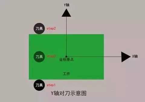
5. Z direction tool adjustment
Move the tool to the part surface where the zero point of the Z direction should be aligned. Slowly move the tool until it lightly touches the top surface of the workpiece. Note the value of the Z direction in the machine coordinate system. at this time, and press (INPUT) to enter the coordinate system.

6. Spindle stops
First, stop the spindle rotation, move the spindle to the appropriate position, call the processing program, and prepare for formal processing.
How does the machining center produce and process easily deformable parts?
Parts with lighter mass, low rigidity and low strength are easily deformed by stress and heat during processing, and the processing scrap rate is high, resulting in a significant increase in costs . For such parts, it is first necessary to understand the causes of deformation:
Deformation due to force:
The walls of these parts are thin, and under the action of clamping force, they are subject to uneven thickness during processing and cutting. The elasticity is poor and the shape of the parts is difficult to find by itself.
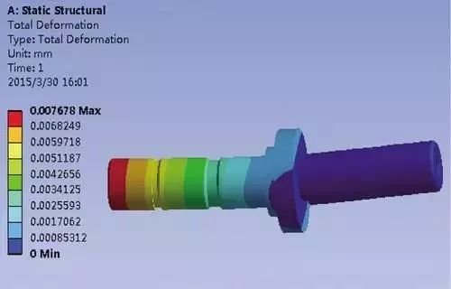
Heat distortion:
The workpiece is light and thin, and the radial force during the cutting process will cause thermal deformation of the workpiece, resulting in inaccurate workpiece dimensions.
Vibration deformation:
Under the action of radial cutting force, workpieces are subject to vibration and deformation, which affects the dimensional accuracy, shape, positional accuracy and surface roughness of the workpiece.
Methods for processing easily deformable parts:
For easily deformable parts represented by thin-walled parts, high-speed machining with low feed and high cutting speed can be used to reduce the cutting force on the part during processing, and at the same time, the Most of the cutting heat is dissipated. away from the workpiece by high-speed chips. Remove it, thereby lowering the room temperature and reducing thermal distortion of the room.
Why do machining center tools need to be passivated?
The faster the CNC tool, the better. Why do we have to passivate it? In fact, tool passivation is not what literally everyone understands, but a way to increase tool life. Improve tool quality through processes such as smoothing, polishing and deburring. This is actually a normal process after the tool is finely ground and before coating.
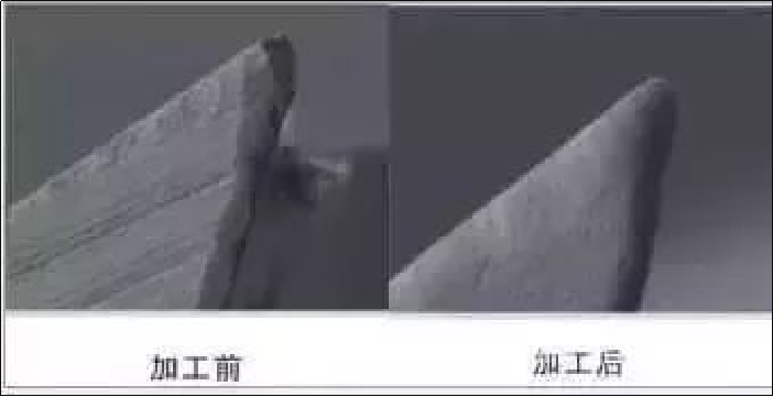
▲ Tool passivation comparison
The tool will be sharpened with a grindstone before being finished, but the sharpening process will cause microscopic chips to varying degrees. As the machining center cuts at high speeds, microscopic gaps easily expand, accelerating tool wear and damage. Modern cutting technology has strict requirements for the stability and precision of cutting tools. Therefore, CNC cutting tools must pass the edge passivation treatment before coating to ensure the firmness and service life of the coating. The advantages of tool passivation are:
1. Resist physical tool wear
During the cutting process, the tool surface will be gradually worn by the workpiece, and the cutting edge is also subject to plastic deformation at high temperature and high pressure during the cutting process. Passivation treatment of cutting tools can help improve the rigidity of cutting tools and prevent premature loss of cutting performance.
2. Maintain the softness of the room
Burrs on the tool cutting edge will cause tool wear and the workpiece surface will become rough. After passivation treatment, the cutting edge of the tool will become very smooth, chipping will be reduced accordingly, and the surface finish of the workpiece will also be improved.
3. Convenient removal of chips from grooves
Polishing the tool grooves can improve the surface quality and chip evacuation performance. The flatter and smoother the groove surface, the better chip evacuation and a more consistent cut can be achieved. After CNC tools are passivated and polished in the machining center, many small holes will remain on the surface. These small holes can absorb more cutting fluid during processing, greatly reducing the heat generated during cutting and greatly improving the efficiency of cutting speed. .
How does the machining center reduce the roughness of the workpiece?
Rough surface of parts is one of the common problems in CNC machining centers, which directly reflects the processing quality. How to control the surface roughness of parts during processing, we must first make a in-depth analysis of the causes of surface roughness, which mainly include: tool marks caused during milling; machined surfaces friction between.
When selecting the surface roughness of the part, it should not only meet the functional requirements of the part, but also consider economic rationality. In order to achieve cutting performance, a larger surface roughness reference value should be used as much as possible to reduce production costs. As an executor of the cutting machining center, the tools should be regularly maintained and sharpened in time to avoid unqualified surface roughness caused by dull tools.
What should I do after finishing the work in the machining center?
Generally speaking, the machining process procedures of traditional machine tools in machining centers are roughly the same. The main difference is that the machining center carries out all cutting processes continuously and automatically via a single clamping. Therefore, the machining center has to do some “after work”. .
1. Carry out cleaning. After the machining center completes the cutting task, it is necessary to quickly remove the chips and wipe the machine tool, and keep the machine tool and the environment clean.
2. When inspecting and replacing accessories, first pay attention to check the oil wiping plate on the guide rail if it is worn, replace it in time. Check the condition of the lubricating oil and coolant. If turbidity occurs, replace it in time. If the water level is below the scale, add more.
3. The shutdown procedure should be standardized, and the power supply of the machine tool control panel and the main power supply should be cut off in sequence. In the absence of special circumstances or requirements, the principles of return to zero first, manual, progressive and automatic must be followed. The machining center should also operate at low speed, medium speed, and then high speed. Low and medium speed running time should not be less than 2-3 minutes without any abnormality before starting work.
4. Standardize the operation. Do not strike, straighten or correct the workpiece on the chuck or at the tip. The part and tool must be confirmed as tight before proceeding to the next step. The safety insurance and protection devices of the machine tool shall not be dismantled or moved at will. The most effective treatment is actually a safe treatment. As an efficient processing equipment, the operation of the machining center should be reasonably standardized during shutdown. This is not only to keep the completed process ongoing, but also to prepare for the next start of work. .
Daguang focuses on providing solutions such as precision CNC machining services (3-axis, 4-axis, 5-axis machining), CNC milling, 3D printing and rapid prototyping services.
