Diagnosing and resolving issues with Computer Numerical Control (CNC) equipment is a critical skill that directly impacts production efficiency, part quality, and operational costs. While modern CNC systems often come with sophisticated proprietary software, a vast number of machines worldwide—from retrofitted mills to custom-built routers—rely on the versatile and widely-used Mach3 motion control software. For engineers and shop managers in the precision parts machining and customization field, understanding how to troubleshoot CNC machine using Mach3 is essential for minimizing downtime and maintaining a seamless production flow. This guide provides a systematic, engineer-driven approach to diagnosing common problems, transforming frustrating breakdowns into structured, solvable puzzles.
The Foundational Mindset: Systematic Diagnosis Before Action
Before diving into specific fixes, adopt a systematic mindset. Haphazardly adjusting parameters or rewiring connections can exacerbate the problem. Effective troubleshooting follows a logical flow: 1) Define the Symptom, 2) Isolate the System, 3) Test Components, and 4) Verify the Fix. Mach3 provides several built-in tools for this process, which we will explore in detail. Remember, the goal is not just to get the machine running again, but to understand the root cause to prevent recurrence—a philosophy embraced by high-reliability suppliers like ourselves at GreatLight CNC Machining Factory, where process stability is paramount.
Phase 1: Initial Assessment & Machine State Verification
When a fault occurs, your first actions should be observational and non-invasive.
Document the Exact Symptom: Be precise. Instead of “the motor is jerky,” note “the X-axis motor stutters at 1500 mm/min feed rate but runs smoothly at 500 mm/min during a specific G01 command.” Record any error messages from Mach3.
Check the Obvious: Ensure all physical connections are secure (power, motor cables, parallel/USB cable). Verify the emergency stop is released. Confirm the machine is properly homed/referenced if required.
Review the Recent Changes: Did the issue start after a new toolpath was loaded, a parameter was changed, or a mechanical component was serviced? This is often the fastest path to a solution.
Phase 2: Leveraging Mach3’s Built-in Diagnostic Tools
Mach3’s interface is a treasure trove of diagnostic information. Familiarize yourself with these key screens:

The “Diagnostics” Screen (Alt+D): This is your primary dashboard. Pay close attention to the Driver Test LED indicators. If these do not respond correctly to manual jog commands from the on-screen buttons, the issue is likely in the communication between Mach3 and the motion controller or the motor drivers themselves.
The “Status” Window: It displays real-time information like commanded vs. actual position, feed rate, and active G/M codes. A discrepancy between commanded and actual position points to a following error, often caused by mechanical binding or insufficient motor tuning.
“Config” > “Ports and Pins” Settings: Incorrect configuration here is a leading cause of failure. Do not modify settings arbitrarily. Have a backup of your proven configuration file (*.xml). If troubleshooting leads you here, check one setting at a time.
Phase 3: Structured Troubleshooting by Symptom Category
Here is a structured approach to common problems, utilizing Mach3’s features.

Category A: Machine Does Not Move or Respond to Commands
Step 1: Software Communication Check.
Open the Diagnostics screen. Click the manual jog arrows for an axis.
Observe: Does the corresponding “X Out” or “Y Out” LED blink? If NO, Mach3 is not sending a signal.
Probable Cause 1: Mach3 is not in “Reset” or “Auto” mode. Ensure the “Reset” LED is lit green.
Probable Cause 2: The parallel port or USB adapter is not correctly assigned or is faulty. Verify the correct “Port Number” in “Ports and Pins.” For USB motion controllers, ensure the driver is installed.
If the LED blinks correctly, the issue is downstream.
Step 2: Signal Path to Motor.
A blinking LED confirms pulse signals are being generated. The next step is the Breakout Board (BOB) and motor drivers.
Use a multimeter (set to DC Volts) to check for voltage change on the Step/Dir pins between the BOB and driver when jogging. No change indicates a faulty BOB or incorrect BOB configuration in Mach3.
If the signal reaches the driver, check the driver’s status LEDs. Ensure it is receiving adequate power and that its enable pin is activated (often a specific input in Mach3’s “Ports and Pins > Input Signals”).
Category B: Axis Moves Erratically, Stutters, or Loses Position
Step 1: Eliminate Mechanical Binding.
Disconnect the motor coupler from the lead screw or ball screw. Can you turn the screw by hand smoothly through its entire travel? Resistance or tight spots indicate mechanical issues—a misaligned bearing, a damaged ball nut, or a overtightened linear guide.
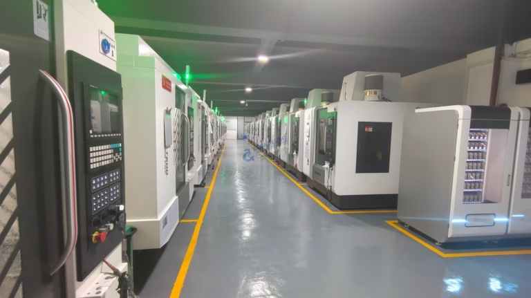
This is critical: No amount of software tuning can compensate for a fundamentally bound mechanical system. Precision equipment, such as the five-axis CNC machining centers we operate at GreatLight CNC Machining Factory, requires impeccable mechanical alignment to achieve tolerances like ±0.001mm.
Step 2: Tune the Motor Drives.
Most stepper and servo drivers have tuning pots for current (amps) and microstepping. An incorrectly set current can cause the motor to overheat and lose torque, leading to stalling.
Refer to your motor and driver datasheets for the correct current setting. Feel the motor temperature after a few minutes of operation; it should be warm, not scalding hot.
Step 3: Optimize Mach3 Motor Tuning.
Navigate to “Config” > “Motor Tuning.”
Velocity and Acceleration: Too high acceleration can cause immediate stalling. Too high velocity can cause lost steps at speed. Reduce these values significantly as a test. A stable, slow move is better than a failed fast one.
Step Pulse and Dir Pulse Width: If these values (in microseconds) are too short for your specific driver, the signal may not be recognized. Increasing them (e.g., from 2µs to 5µs) can add stability.
Use the “Test” button in this menu to run the axis back and forth and observe its behavior.
Category C: Cuts are Inaccurate or Part Dimensions are Wrong
Step 1: Verify G-Code.
Use Mach3’s toolpath visualizer. Does the preview look correct? A stray G-code command (e.g., an unwanted G91 for incremental mode) can ruin a part.
Check for correct units (G21 for mm, G20 for inches). This is a common oversight.
Step 2: Check for Backlash.
Command a move in one direction (e.g., +X 10mm), then reverse (-X 10mm). Does the tool return to the exact start position? Use a dial indicator to measure any discrepancy—this is backlash.
While Mach3 has a software backlash compensation feature (“Config” > “Backlash”), it is a corrective patch, not a cure. The proper solution is to mechanically eliminate backlash by adjusting or replacing worn ball nuts, couplings, or pre-tensioning anti-backlash mechanisms.
Step 3: Calibrate Steps Per Unit.
This is fundamental. Command a precise move (e.g., 100.0 mm). Measure the actual travel with a high-precision gauge.
The formula is: *New Steps/mm = (Old Steps/mm Commanded Distance) / Actual Measured Distance.**
Update this value in the “Motor Tuning” dialog. Repeat the measurement to confirm. In a professional setting like ours, this calibration is part of a rigorous routine maintenance schedule, underpinned by our ISO 9001:2015 certified quality management system.
Conclusion: From Troubleshooting to Trusted Partnership
Mastering how to troubleshoot CNC machine using Mach3 empowers you to maintain control over your manufacturing process. It transforms you from a passive operator to an active engineer, capable of diagnosing issues from software configuration to mechanical wear. The systematic approach outlined—leveraging diagnostic tools, isolating subsystems, and methodically testing—is the same engineering discipline applied on a larger scale at advanced manufacturing partners.
While this guide equips you to handle many challenges, some situations—particularly those involving complex multi-axis kinematics, intricate servo tuning, or systemic mechanical refurbishment—require the deep technical resources of a specialized provider. When your internal capacity is stretched, or when you require parts machined with guaranteed precision and reliability from the outset, partnering with an expert becomes the most efficient strategic choice.
This is where a full-service, technically adept manufacturer demonstrates its value. A partner like GreatLight CNC Machining Factory doesn’t just supply parts; it brings an integrated system of advanced 5-axis CNC equipment, metrology-backed process control, and engineering support to bear on your project. We solve the manufacturing challenges so you can focus on design and innovation. For your most demanding precision machining and customization needs, engaging a partner with this depth of capability is often the ultimate solution to avoiding operational “troubleshooting” altogether.
Frequently Asked Questions (FAQ)
Q1: Is this Mach3 troubleshooting guide applicable to other control software like Mach4, UCCNC, or LinuxCNC?
A: The core principles of systematic diagnosis—isolating software, electronics, and mechanics—are universal. However, the specific menus, terminology, and diagnostic tools differ significantly between software platforms. Always refer to your specific software’s manual.
Q2: My machine has a persistent vibration or resonance at certain speeds. What can I do in Mach3?
A: This is often a mechanical resonance issue. In Mach3’s “Motor Tuning,” you can enable and configure “Smoothing” (also called Jerk Control or CV Distance). This filters the motion commands to dampen sharp acceleration changes that can excite resonance. Additionally, ensure all mechanical components (motor mounts, bearing blocks) are rigidly fastened.
Q3: When should I seek professional help instead of troubleshooting myself?
A: Consider professional assistance when: the problem involves high-voltage spindle drives or complex servo systems (risk of injury or damage); you suspect a major mechanical failure (e.g., a cracked casting, damaged linear guide); or prolonged downtime is costing more than a service call. A professional service engineer from your machine builder or a qualified integrator can often diagnose and resolve issues much faster.
Q4: Are there hardware tools that make Mach3 troubleshooting easier?
A: Absolutely. Essential tools include a digital multimeter for checking voltages and continuity, a dial test indicator for measuring backlash and runout, and a non-contact infrared thermometer to check motor and driver temperatures. For signal inspection, a simple parallel port LED tester can visually confirm if Mach3 is sending step pulses.
Q5: How do companies like GreatLight Metal ensure these machine issues don’t affect client parts?
A: Professional manufacturers implement layers of prevention. This includes: Preventive Maintenance (PM) schedules to catch wear before it causes failure; comprehensive first-article inspection using CMMs and other metrology tools to verify machine accuracy before a production run; and process qualification under standards like IATF 16949 for automotive or ISO 13485 for medical, which mandate strict control over equipment calibration and maintenance. This systemic approach minimizes the chance of a machine fault translating into a non-conforming part.


