127 Sets Processing 4000mm 127 Sets High-Precision CNC Lathes
15 Years of Experience

CNC Knowledge: Do you understand cycloid milling?

Unlocking Manufacturing Potential: The Science and Strategy Behind Cycloid Milling Move beyond traditional machining bottlenecks. Cycloid milling is revolutionizing high-performance material removal, offering manufacturers unprecedented efficiency, tool longevity, and surface quality in demanding applications across aerospace, automotive, mold & die, and beyond. This in-depth exploration reveals why and how this cutting-edge strategy delivers unparalleled results. […]

WeChat picture_20250522104007.png

Unlocking Manufacturing Potential: The Science and Strategy Behind Cycloid Milling

Move beyond traditional machining bottlenecks. Cycloid milling is revolutionizing high-performance material removal, offering manufacturers unprecedented efficiency, tool longevity, and surface quality in demanding applications across aerospace, automotive, mold & die, and beyond. This in-depth exploration reveals why and how this cutting-edge strategy delivers unparalleled results.

Demystifying the Cycloid: Beyond Conventional Paths

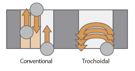
Forget linear or simple curved tool paths defining traditional machining. Cycloid milling harnesses a sophisticated, dynamic motion based on circular fragmentation. The cutting tool engages the workpiece in a series of continuously adapting circular arcs with varying diameters. The resulting trajectory? A precise, spiral-like "cycloidal" path. This complex movement fundamentally shifts how the tool interacts with the material. Instead of constant, grinding friction, cycloid milling creates intermittent engagement – the tool cuts, lifts, moves, and re-engages in a calculated, cyclic pattern.

The core mechanics rely on programming the tool’s center point to trace this specialized path around the desired groove or hole, which itself can be significantly larger than the physical diameter of the cutting tool. This capability is particularly transformative for cavity milling, slotting, pocketing, and dealing with complex internal geometries. Crucially, this methodology minimizes sustained friction and heat generation while maximizing chip evacuation efficiency.

The Engineered Edge: Why Cycloid Milling Outperforms

The shift from constant to intermittent contact unlocks a cascade of performance benefits:

  1. Radical Material Removal Rates (MRR): By optimizing the tool path for minimal engagement time per rotation, cycloid milling allows significantly higher cutting speeds without compromising tool integrity. Combined with the ability to utilize near-full axial depths of cut, this translates directly to faster machining cycles and soaring productivity.
  2. Revolutionary Tool Life Extension: Reducing friction equals less heat. Less heat means drastically reduced tool wear. The intermittent cutting action effectively gives the cutting edges time to cool between engagements, dramatically prolonging tool lifespan and significantly lowering per-part tooling costs, especially when machining tough alloys or composites.
  3. Superior Chip Evacuation: The inherent spiral motion acts like a conveyor belt for chips. This dynamic flushing effect prevents chip recutting, a primary cause of tool damage, poor surface finish, and heat buildup. Efficient chip evacuation is critical in deep pockets and challenging materials like aluminum or titanium.
  4. Exceptional Surface Finish Potential: Shorter contact duration per revolution and minimized vibration through optimized engagement significantly reduce chatter marks and irregular tool pressure. The result is consistently smoother surface finishes, often reducing or eliminating secondary finishing operations.
  5. Dramatically Reduced Cutting Forces: By engaging only a small radial portion of the tool edge per revolution while leveraging the full axial flute length, cycloid milling achieves its high MRR with surprisingly low radial cutting forces. This enables:
    • Machining high-value parts on smaller, less rigid CNC machines previously unsuitable for aggressive cutting.
    • Minimizing part distortion or vibration in thin-walled or delicate components.
    • Pushing machine spindles harder without exceeding their torque or rigidity limits.
  6. Unmatched Adaptability & Tool Economy: The cycloid path inherently generates a working diameter larger than the tool’s physical diameter. Strategically, this means one cutter can machine features of varied sizes (e.g., different slot widths or pocket dimensions). This radically minimizes the need for extensive tooling inventories.
  7. Power Efficiency: Achieving aggressive MRR with lower forces means cycloid milling efficiently leverages the available spindle power on lower-horsepower machining centers, maximizing their output potential without requiring massive capital investment.

Material Mastery: Where Cycloid Milling Shines

Cycloid milling demonstrates remarkable versatility across a broad material spectrum, but strategic considerations enhance its effectiveness:

  • Metals (Steel, Stainless Steel, Aluminum, Titanium): A primary domain, excelling by reducing forces and improving chip evacuation. Especially valuable for stainless steels prone to work hardening and gummy aluminum where chip control is critical.
  • Thermosensitive & Difficult-to-Machine Alloys (Inconel, Waspaloy, Titanium Alloys): The minimized heat generation is paramount here. Cycloid milling protects part metallurgy by preventing thermal damage and drastically extends tool life in these notoriously abrasive and tough materials common in aerospace.
  • Advanced Composites (CFRP, GFRP): Effectively manages the abrasive nature and delamination risk. The intermittent cut and gentle entry/exit reduce fiber tear-out and fraying, leading to cleaner cuts and improved surface integrity.
  • Hardened Materials (Tool Steels (>45 HRC), Hard Coatings): The low-force approach allows practical machining of hardened steels and metals where traditional methods struggle, boosting efficiency in mold & die work.
  • Non-Metallic Materials (Plastics, Exotic Polymers, Wood): Mitigates heat build-up (crucial for preventing melting or warping in thermoplastics) and significantly reduces tool abrasion, ensuring cleaner cuts and longer cutter life.

Material Optimization is Key: While broadly applicable, success hinges on tailoring cutting parameters (speeds, feeds, engagement angles), tool geometries (helix angles, rake angles), and coatings (AlTiN, DLC suitable for specific materials) to the specific workpiece material and desired operation.

Mastering Implementation: Proven Techniques for Success

Applying cycloid milling effectively demands more than just enabling the toolpath in CAM software. Leverage these critical best practices:

  1. Strategic Tool Selection:
    • Full Solid Carbide: Non-negotiable for rigidity to handle dynamic forces. Integral shank designs minimize deflection.
    • High-Performance Coatings: AlTiN, AlTiCrN, and DLC variants drastically enhance lubricity, heat resistance, and reduce adhesion for specific materials. PARK TiCo 4BC coating delivers high performance in steel and aluminum.
    • Cutting Edge & Flute Count: Prioritize tools with robust edge preparation for toughness. Use multiple flutes (5-7+) to maximize metal removal per spindle revolution – the intermittent nature allows this without overheating. Variable Helix/Uneven Pitch designs are highly recommended to suppress harmonics and chatter.
  2. Parameter Optimization:
    • Embrace High RPMs: Utilize your spindle’s full potential. Reduced contact time permits significantly higher surface speeds (SFM/m/min) than conventional approaches.
    • Feed Rate Synergy: Match high RPM with aggressive feed rates (IPM/mm per min), ensuring optimal Chip Load Per Tooth (CPT/CLPT) based on tool/material. Required for efficient chip formation and energy distribution.
    • Path Geometry: Optimize the "stepping diameter" of the cycloid loops (often 5-15% of tool diameter). Fine-tune overlap ratios to balance cycle time and tool life.
  3. Smart Toolpath Engineering:
    • Leverage Advanced CAM: Utilize CAM systems offering robust cycloid/trochoidal strategies. Control entry/exit, overlap, stepover adaptation, and transition efficiency.
    • Entry/Exit Strategies: Craft smooth, tangential engagement paths into the cycloid spiral to reduce shock loading.
  4. Prioritize Chip Evacuation:
    • Program Strategically: Ensure toolpaths facilitate chip movement out of the cut zone. Avoid trapping chips.
    • High-Pressure Coolant (HPC): Essential for deep pockets and challenging materials. Direct high-pressure streams precisely at the cutting edge for cooling and chip evacuation.
    • Air Blast/Mist: Effective alternatives for materials incompatiblc with flood coolant (e.g., some composites).
  5. Maximize Rigidity:
    • Secure Workholding: Ensure the workpiece is clamped rock-solid to resist the machining forces.
    • Minimize Tool Overhang: Use the shortest possible tool length extension from the holder.
    • Premium Tool Holders: Utilize Hydraulic, Shrink Fit, or HIGH-PRESSURE Collet holders for supreme clamping force and damping – heat shrink toolholders such as thermogrip is also a premium cutting tool clamping solution.
    • Stable Fixturing: Ensure machine/workpiece vibrations are damped effectively. Damping toolholders can assist.

The Future is Cycloidal

Cycloid milling transcends being a mere toolpath option; it’s a holistic strategy for high-efficiency machining. By intelligently managing forces, friction, heat, and chips, it unlocks new levels of productivity, cost-efficiency, and capability, particularly on existing and less powerful CNC machine tools. As CAM software continues to evolve and machine tool capabilities increase, the adoption and sophistication of cycloid milling will only accelerate. Implementing its principles today positions manufacturers at the leading edge of competitive machining performance.

Key Visual Concepts for Layout:

  1. Schematic Animation: Illustration showing tool center path tracing a cycloid spiral vs. conventional linear slotting tool path (Top-Down View).
  2. Thermal Imaging Comparison: Thermal map overlays showing heat concentration on a tool using conventional path vs. minimal heat zones with cycloid path (Side View).
  3. Material Compatibility Matrix: Visual chart depicting material groups (Aluminum, Steel, Titanium, Composites, Plastics) with icons indicating Cycloid Suitability (High/Medium) and key tool/parameter recommendations.
  4. Tool Anatomy Highlight: Image labeling a specialized end mill showing features critical for Cycloid Milling: Solid Carbide Body, Robust Cutting Edges, Variable Helix/Uneven Pitch, Specific Coating.
  5. Chip Evacuation Flow: Diagram showing chips efficiently propelled along the flute gullets by the spiral path and coolant streams, away from the cutter/workpiece contact zone.

CNC Experts

Picture of JinShui Chen

JinShui Chen

Rapid Prototyping & Rapid Manufacturing Expert

Specialize in CNC machining, 3D printing, urethane casting, rapid tooling, injection molding, metal casting, sheet metal and extrusion

CNC Recent Posts

CNC News

Welcome to GreatLight Metal,Maximum Processing Size 4,000 mm

Precision Machining CNC Quote Online

Loading file

Upload Click here to upload or drag and drop your model to the canvas.

The model is too large and has been resized to fit in the printer's build tray. [Hide]

The model is too large to fit in the printer's build tray. [Hide]

The model is too large, a fitting printer is selected. [Hide]

The model is too small and has been upscaled. [Hide]

Warning: The selected printer can not print in full color [Hide]

Warning: obj models with multiple meshes are not yet supported [Hide]

Warning: Unsupported DXF entity  [Hide]

Warning: could not arrange models [Hide]


File Unit:      
Scale:
%
L × W × H:
X: × Y: × Z:  cm 
Rotation:
X: ° Y: °  
⚡ Instant Quote for Precision Manufacturing

Submit your design files (STEP/IGES/DWG) and receive a competitive quote within 1 hour, backed by ISO 9001-certified quality assurance.

📋 How It Works

  1. Upload & SpecifyShare your 3D model and select materials (Aluminum/Stainless Steel/Titanium/PEEK), tolerances (±0.002mm), and surface treatments.

  2. AI-Powered AnalysisOur system calculates optimal machining strategy and cost based on 10+ years of automotive/aerospace data.

  3. Review & ConfirmGet a detailed breakdown including:
    - Volume pricing tiers (1-10,000+ units)
    - Lead time (3-7 days standard)
    - DFM feedback for cost optimization

Unit Price: 

Loading price
5 Axis CNC Machining Equipment
4 Axis CNC Machining Equipment
3 Axis CNC Machining Equipment
CNC Milling & Turning Equipment
Prototype and Short-Run Injection Moldings Exact plastic material as final design
Volume Metal Die Casting Services - Precision Cast Parts
Bridge the Gap From Prototype to Production – Global delivery in 10 days or less
Custom high-precision sheet metal prototypes and parts, as fast as 5 days.
Custom Online 3D Printing Services
Design Best Processing Method According To 3D Drawings
Alloys Aluminum 6061, 6061-T6 Aluminum 2024 Aluminum 5052 Aluminum 5083 Aluminum 6063 Aluminum 6082 Aluminum 7075, 7075-T6 Aluminum ADC12 (A380)
Alloys Brass C27400 Brass C28000 Brass C36000
Alloys Stainless Steel SUS201 Stainless Steel SUS303 Stainless Steel SUS 304 Stainless Steel SUS316 Stainless Steel SUS316L Stainless Steel SUS420 Stainless Steel SUS430 Stainless Steel SUS431 Stainless Steel SUS440C Stainless Steel SUS630/17-4PH Stainless Steel AISI 304
Inconel718
Carbon Fiber
Tool Steel
Mold Steel
Alloys Titanium Alloy TA1 Titanium Alloy TA2 Titanium Alloy TC4/Ti-6Al 4V
Alloys Steel 1018, 1020, 1025, 1045, 1215, 4130, 4140, 4340, 5140, A36 Die steel Alloy steel Chisel tool steel Spring steel High speed steel Cold rolled steel Bearing steel SPCC
Alloys Copper C101(T2) Copper C103(T1) Copper C103(TU2) Copper C110(TU0) Beryllium Copper
Alloys Magnesium Alloy AZ31B Magnesium Alloy AZ91D
Low Carbon Steel
Alloys Magnesium Alloy AZ31B Magnesium Alloy AZ91D
ABS Beige(Natural) ABS Black ABS Black Antistatic ABS Milky White ABS+PC Black ABS+PC White
PC Black PC Transparent PC White PC Yellowish White PC+GF30 Black
PMMA Black PMMA Transparent PMMA White
PA(Nylon) Blue PA6 (Nylon)+GF15 Black PA6 (Nylon)+GF30 Black PA66 (Nylon) Beige(Natural) PA66 (Nylon) Black
PE Black PE White
PEEK Beige(Natural) PEEK Black
PP Black PP White PP+GF30 Black
HDPE Black HDPE White
HIPS Board White
LDPE White
This is a finish of applying powdered paint to the components and then baking it in an oven, which results in a stronger, more wear- and corrosion-resistant layer that is more durable than traditional painting methods.
No coating required, product’s natural color!
This is a finish of applying powdered paint to the components and then baking it in an oven, which results in a stronger, more wear- and corrosion-resistant layer that is more durable than traditional painting methods.
This finishing option with the shortest turnaround time. Parts have visible tool marks and potentially sharp edges and burrs, which can be removed upon request.
Sand blasting uses pressurized sand or other media to clean and texture the surface, creating a uniform, matte finish.
Polishing is the process of creating a smooth and shiny surface by rubbing it or by applying a chemical treatmen
A brushed finish creates a unidirectional satin texture, reducing the visibility of marks and scratches on the surface.
Anodizing increases corrosion resistance and wear properties, while allowing for color dyeing, ideal for aluminum parts.
Black oxide is a conversion coating that is used on steels to improve corrosion resistance and minimize light reflection.
Electroplating bonds a thin metal layer onto parts, improving wear resistance, corrosion resistance, and surface conductivity.
This is a finish of applying powdered paint to the components and then baking it in an oven, which results in a stronger, more wear- and corrosion-resistant layer that is more durable than traditional painting methods.
Please provide additional text description for other surface treatment requirements!
Material
Material
  • CNC Metals
    • Aluminum
    • Brass
    • Stainless steel
    • Inconel718
    • Carbon Fiber
    • Tool Steel
    • Mold Steel
    • Titanium
    • Alloy Steel
    • Copper
    • Bronze
    • Low Carbon Steel
    • Magnesium
  • CNC Plastics
    • ABS
    • PC
    • PMMA (Acrylic)
    • PA (Nylon)
    • PE
    • PEEK
    • PP
    • HDPE
    • HIPS
    • LDPE
Printer
Printer
  • CNC Metals
    • 5 Axis CNC Machining
    • 4 Axis CNC Machining
    • 3 Axis CNC Machining
    • CNC Milling & Turning
    • Rapid Tooling
    • Metal Die Casting
    • Vacuum Casting
    • Sheet Metal Fabrication
    • SLA 3D Printing
    • SLS 3D Printing
    • SLM 3D Printing
  • Rapid Prototyping
    • Design Best Processing Method According To 3D Drawings
Post-processing
Post-processing
  • As Machined(Product’s natural color)
  • Sand Blasting
  • Polishing
  • Brushed Finish
  • Anodizing
  • Black Oxide
  • Electroplating
  • Paint Coating
  • Powder Coating
  • Other surface treatment requirements
Finalize
The world's first CNC machining center that dares to provide free samples!

Free for first product valued at less than $200. (Background check required)

precision machining cnc quote online

15 Years CNC Machining Services

When you’re ready to start your next project, simply upload your 3D CAD design files, and our engineers will get back to you with a quote as soon as possible.
Scroll to Top

ISO 9001 Certificate

ISO 9001 is defined as the internationally recognized standard for Quality Management Systems (QMS). It is by far the most mature quality framework in the world. More than 1 million certificates were issued to organizations in 178 countries. ISO 9001 sets standards not only for the quality management system, but also for the overall management system. It helps organizations achieve success by improving customer satisfaction, employee motivation, and continuous improvement. * The ISO certificate is issued in the name of FS.com LIMITED and applied to all the products sold on FS website.

greatlight metal iso 9001 certification successfully renewed
GB T 19001-2016 IS09001-2015
✅ iso 9001:2015
greatlight metal iso 9001 certification successfully renewed zh

IATF 16949 certificate

IATF 16949 is an internationally recognized Quality Management System (QMS) standard specifically for the automotive industry and engine hardware parts production quality management system certification. It is based on ISO 9001 and adds specific requirements related to the production and service of automotive and engine hardware parts. Its goal is to improve quality, streamline processes, and reduce variation and waste in the automotive and engine hardware parts supply chain.

automotive industry quality management system certification 01
Certification of Production Quality Management System for Engine Hardware Parts Engine Hardware Associated Parts
automotive industry quality management system certification 00
发动机五金零配件的生产质量管理体系认证

ISO 27001 certificate

ISO/IEC 27001 is an international standard for managing and processing information security. This standard is jointly developed by the International Organization for Standardization (ISO) and the International Electrotechnical Commission (IEC). It sets out requirements for establishing, implementing, maintaining, and continually improving an information security management system (ISMS). Ensuring the confidentiality, integrity, and availability of organizational information assets, obtaining an ISO 27001 certificate means that the enterprise has passed the audit conducted by a certification body, proving that its information security management system has met the requirements of the international standard.

greatlight metal technology co., ltd has obtained multiple certifications (1)
greatlight metal technology co., ltd has obtained multiple certifications (2)

ISO 13485 certificate

ISO 13485 is an internationally recognized standard for Quality Management Systems (QMS) specifically tailored for the medical device industry. It outlines the requirements for organizations involved in the design, development, production, installation, and servicing of medical devices, ensuring they consistently meet regulatory requirements and customer needs. Essentially, it's a framework for medical device companies to build and maintain robust QMS processes, ultimately enhancing patient safety and device quality.

greatlight metal technology co., ltd has obtained multiple certifications (3)
greatlight metal technology co., ltd has obtained multiple certifications (4)

Get The Best Price

Send drawings and detailed requirements via Email:[email protected]
Or Fill Out The Contact Form Below:

All uploads are secure and confidential.