
China Chinese Rapid Tooling Exporter Service: What Engineers Should Check
This page explains how a china chinese rapid tooling exporter service actually runs a project, from DFM feedback to first-article approval. It is written for design engineers and sourcing leads who need to decide whether a tool can be built and proven at a distance. After reading, you can judge which tool types fit your part, which steel and tolerance grade make sense, and where the real risks sit.
Rapid Tooling Is a Process, Not a Machine
A tool that arrives fast but cannot hold dimension is not rapid. What matters is how many steps run under one roof.
What Counts as Rapid Tooling
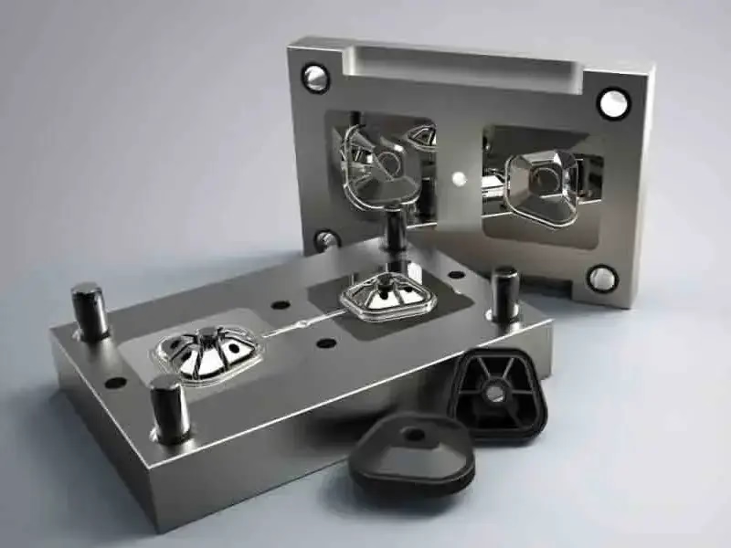
Rapid tooling covers any mold or die built to bridge the gap between a prototype and a hardened production tool. It is not one process. Depending on part size, volume and material, a shop may cut a prototype cavity in aluminum, machine a P20 steel tool for a few thousand shots, or build a bridge tool that runs the same gate layout as the final mold. Each path has a different price and life.
The distinction that matters for sourcing is what happens after the cavity is cut. A mold is only finished when the core and cavity fit, the ejector system moves without binding, cooling lines flow at the designed rate, and the first shots are dimensionally checked against the drawing. If those steps are split across vendors, the schedule slips and nobody owns the result.
A real china chinese rapid tooling exporter service runs design review, machining, EDM, fitting, polishing and first-article inspection as one sequence. That is the difference between a fast tool and a tool that is ready to run.
- 1Prototype toolAluminum or soft steel, low shot count, for fit and function checks
- 2Bridge toolSteel cavity, gate layout matches production, for market testing
- 3Production toolHardened steel, engineered cooling, for long runs
The DFM Review Sets the Tool's Fate
Most tooling problems are visible on the drawing before any metal is cut. Draft angle below 1°, wall thickness stepping from 3 mm to 0.8 mm, a rib that crosses a deep boss, or a snap fit that needs side action. Catching these changes costs a few hours. Catching them after heat treat costs a re-cut.
We return quotation and free DFM analysis within 12 hours of receiving a STEP file and a 2D drawing with tolerances. The review lists draft adjustments, suggested gate positions, ejector pin locations, and any feature that needs a slide or lifter. It also flags where the part tolerance is tighter than the process can hold, so the conversation happens before the design is frozen.
Engineers should send the 2D drawing, not just the 3D model. A STEP file carries geometry. It does not carry the datum scheme, the critical dimensions, or which surfaces are cosmetic. Tooling decisions depend on all three.
Cavity and Core Machining: Where the Tolerance Lives
Roughing removes most of the stock. The finishing passes decide whether the tool works. On a deep cavity, a long small-diameter tool deflects, so the shop has to control stepover, feed and tool projection together. This is why the machine mix matters more than the machine count.
GreatLight runs 16 simultaneous 5-axis machining centers, 12 four-axis mills, 27 three-axis machines and 16 mill-turn centers, 127 high-precision CNC machines in total across three wholly-owned plants covering 7,600 m². The 5-axis centers handle contoured cores and angled gate pads in one setup. Three-axis machines take the flat plates and mold bases. Maximum processing size is 4,000 mm, with travels of 4,000 × 400 × 150 mm and 750 × 1,150 × 550 mm.
Holding ±0.005 mm (±0.0002 in) on a mold insert is not the same as holding it on a shaft. The insert has to seat in its pocket, so the pocket and the insert are machined to a matched fit. We measure both and record the result. Reports are available on request.
- 15-axisContoured cores, angled pads, reduced setups
- 2EDMSharp internal corners and deep ribs a cutter cannot reach
- 3FittingMatched pocket and insert, checked before assembly
Which Tool Build Fits Your Program
Match the tool to the volume and the material, not to the fastest option.
| Tool type | Cavity material | Typical fit | When it stops making sense |
|---|---|---|---|
| Prototype tool | Aluminum 7075 / ADC12 | Fit and function builds, small runs | Part needs abrasive filled resin |
| Bridge tool | P20 or 718 steel | Market test, gate layout equals final | Volume exceeds tool life estimate |
| Production tool | Hardened 1.2343 / 1.2344 | Long runs, tight cycle time | Design still changing weekly |
| Die cast tool | H13 with thermal fatigue check | Aluminum or zinc castings | Wall under 1.0 mm |
| Vacuum cast master | Silicone from CNC pattern | 25 to 50 urethane parts | Part needs real resin properties |
Steel, Aluminum and the Cost of Getting It Wrong
Aluminum cuts fast and polishes to a fine finish, which is why it dominates prototype tools. It also wears. On a glass-filled nylon part, an aluminum cavity can lose edge sharpness within a few hundred shots. If the part uses 30% glass fiber, the tool should be steel from the start, even for a low volume run.
For steel tools, P20 and 718 cover most bridge work. Hardened 1.2343 and 1.2344 come in when the cycle count climbs or the resin is corrosive. We machine tool steel, 4130, 4140, 4340 and 1018, plus 6061, 7075 and 2024 aluminum, and 303, 304, 316 and 17-4PH stainless for inserts, slides and cores.
Cooling layout follows the part, not the mold base. A part with a thick section needs a baffle or bubbler close to the heat. A thin, flat part needs even line spacing. If the cooling is designed after the cavity, cycle time suffers and warpage shows up in the first article.
First Article, Sampling and What Gets Measured
A tool is proven by parts, not by a dimensional report on the cavity. We run the tool, collect a shot sample, and measure the features that carry the function: mating surfaces, bore positions, snap fits, and any dimension marked as critical on the drawing. The report goes out with the sample.
Inspection runs through raw material check, in-process monitoring and final inspection, with 100% inspection before shipment. Across production, the qualification rate stands at 99.99%. Those numbers are process results, not a promise about any single order. They describe how the shop measures and records its work.
For a mold project, the useful deliverable set is: the tool, a first-article sample with report, a cooling and gate layout drawing, and the setup sheet. If a supplier will not hand over the layout drawing, the tool is hard to maintain later.
- 1Dimensional reportCritical features measured against the 2D drawing
- 2First-article sampleShot from the finished tool, not a machined proxy
- 3Layout drawingGate, runner and cooling paths documented
Schedule, Freight and the Real Timeline
Quotation and DFM analysis come back within 12 hours. Production can start within 24 hours of approval. Parts ship in 3 to 5 days for machined work. Those figures apply to CNC parts and simple tool components. A full mold with slides and a hardened cavity follows a longer path: steel procurement, roughing, heat treat, finishing, fitting and sampling.
Freight is part of the timeline, not separate from it. A tool that ships by air in five days still needs a week of sampling at the destination if the molder has to fit it to a press. Planning the sampling step into the schedule avoids the surprise.
Historical late-delivery probability sits below 2%. That is a record, not a guarantee. For projects with a hard launch date, share the date at the quote stage so the sequence can be built around it.
Questions Engineers Ask Before Releasing a Tool
Can you build a tool from a 3D model only?
Yes, but the 2D drawing should follow. The model gives geometry; the drawing gives datums, tolerance class and which surfaces are cosmetic.
Without the drawing we will apply general tolerances and standard draft, and note the assumptions in the DFM report so you can correct them before cutting.
Do you handle low volumes as well as full production tools?
Yes. There is no minimum order quantity, from one prototype to 10,000+ part runs.
For a handful of parts, vacuum casting from a CNC master is often cheaper than a steel tool. For a few thousand shots in a non-abrasive resin, an aluminum or P20 tool usually wins on total cost.
Which certifications cover a tooling project?
GreatLight holds ISO 9001:2015, IATF 16949:2016, ISO 13485:2016 and ISO 27001:2022.
IATF 16949 applies to automotive and EV programs, ISO 13485 to medical device work. ISO 27001 covers information security, which matters when drawings and CAD data leave your network.
How is my design data protected?
Uploads are secure and confidential. An NDA is available on request before any file is shared.
Access to project data is limited to the engineers working on the job.
What surface finish can the mold cavity reach?
Cavity and core surfaces are polished to the finish the part requires. Our machining finishes run from Ra 0.2–0.8 μm for fine work to Ra 1.6–3.2 μm as machined.
A high-gloss cosmetic surface needs more polishing time, and that should be stated at the quote stage rather than discovered at sampling.
Can you supply both the tool and the molded parts?
Yes. Tooling, sampling and low-volume molding can run as one project, which keeps the first article and the tool in the same measurement chain.
If you mold in-house, we ship the tool with the layout drawing, first-article report and setup sheet.
Send a Drawing, Get a Tooling Plan
Share your STEP file and 2D drawing. We return quotation and DFM feedback within 12 hours, with the tool type, steel and lead time spelled out.
DFM in 12 hours±0.005 mm100% inspectionNDA on request









