
Capable CNC Alloy Machining Services: How to Judge One
This page is for engineers and buyers who need alloy parts cut to spec, not just quoted. It covers alloy-specific tolerances, tooling and thermal behavior, inspection evidence, and the cases where a shop should say no. Read it and you can compare suppliers on facts instead of claims.
What This Page Covers
Alloy machining is judged on what the machine, the tool, and the inspection report can hold across a batch, not on a single good sample.
Alloy-Specific Tolerances and Where They Come From
A tolerance is only meaningful when tied to a feature and an alloy. On a 6061 aluminum bracket, holding ±0.005 mm on a bored bore is routine. The same callout on a 3 m long 316L shaft is a different job because thermal drift over the part length moves with the shop temperature, not with the operator's skill. A shop worth calling capable starts by asking which dimensions carry function and which are drawing furniture.
Titanium TC4 (Ti-6Al-4V) is the usual test case. Its thermal conductivity is low, so heat stays at the cutting edge and the material work-hardens under a dull tool. That pushes you toward lower surface speed, higher feed per tooth, and a rigid setup. Stainless 316L wears tools faster and galls, so we change inserts on a count rather than on a feeling. These choices decide whether the second hundred parts match the first one.
Reading an Alloy List Instead of Counting It
Material lists are easy to pad. The useful question is which alloys the shop cuts every week and which it has cut twice. Aluminum 6061, 7075, 2024, 5052 and 6082 behave in well-known ways and are low risk. Stainless 303, 304, 316L, 17-4PH and 440C are also routine, though 316L and 17-4PH need different feeds and, in the case of 17-4PH, a decision about condition before machining.
Then there is the group that separates shops: Inconel, magnesium AZ31B and AZ91D, beryllium copper, and tool steel. Magnesium needs chip control and fire-safe handling. Beryllium copper needs dust control. Inconel punishes light passes and rewards a heavy, steady cut with plenty of coolant. A supplier who lists these alloys should be able to name the tooling and the coolant they use on them.
Ask what happens when a job lands on the wrong side of the list. A good answer is specific: we run a test cut, we send the first article with a dimensional report, and we tell you before the run if the tolerance is not realistic on that alloy. That last part matters more than the brochure.
Alloy Groups and Typical Machining Behavior
General shop-floor behavior on a rigid 3-axis or 5-axis setup. Exact parameters depend on the feature and the tool.
| Alloy group | Behavior at the cut | What to watch |
|---|---|---|
| Aluminum 6061 / 7075 | Free cutting, good finish | Chip evacuation on deep pockets |
| Stainless 316L | Work-hardens, galls | Tool wear, feeds too light |
| 17-4PH | Strong, abrasive | Condition before machining |
| Titanium TC4 | Low heat transfer | Heat at edge, chatter |
| Inconel 718 | Very abrasive, springy | Rigidity, coolant volume |
| Magnesium AZ91D | Light, fast cutting | Chip and fire control |
| Beryllium copper | Hard, conductive | Dust control, tool life |
Process Chains, Setups, and the Cost of a Second Op
A part that needs five setups is not a machining problem, it is a fixturing problem. Each setup adds a datum shift and a chance for error. When we quote an alloy part, we look first at how many faces need work and whether a 5-axis center can reach them in one chucking. With 16 simultaneous 5-axis centers, a lot of brackets and housings that used to need three operations now need one.
Size sets the limit. The largest travel on our floor is 4,000 × 400 × 150 mm, which covers long rails and beams. Mid-size work runs on 750 × 1,150 × 550 mm and 600 × 600 × 600 mm machines. Compact parts, including medical and electronics housings, run on 500 × 500 × 450 mm and 500 × 310 × 200 mm machines, sometimes with a Ø400 mm rotary table for round features.
Turning and milling on one platform is the other lever. Mill-turn centers cut a shaft and its cross-holes without a second fixture, which keeps concentricity where it belongs. If your drawing has a true position callout between a turned diameter and a milled slot, that is the setup to ask for.
Inspection Evidence You Can Audit
A first article inspection report is the minimum. The stronger evidence is in-process. On alloy work we check raw material certificates on arrival, monitor critical dimensions during the run, and inspect 100% of parts before shipment. Reports go out on request. We do not ship a batch and then look for the numbers.
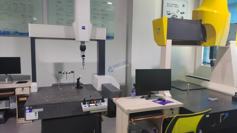
A coordinate measuring machine and optical tools verify what the drawing asks for. The catch is what you ask for. If the drawing calls a profile tolerance on a surface that flexes under clamping, the CMM will measure the relaxed part and the number will move. Send the datum scheme and the functional intent with the model and the report becomes useful.
Our historical qualification rate is 99.99%, and late-delivery probability sits below 2%. Both numbers come from tracking every order, not from a sample. They are also not a substitute for a conversation about your specific part, which is where most alloy problems are actually solved.
When Tight Tolerances Are the Wrong Answer
Not every alloy part should be quoted to ±0.005 mm. If a bracket is held by slotted holes and a rubber gasket, a ±0.05 mm callout buys nothing and adds cost. We will say so. Tightening a tolerance that does not matter takes machine time from the features that do.
There are also cases we turn down. A 4,000 mm weldment in Inconel with a ±0.01 mm flatness callout is not a machining job, it is a fixturing and stress-relief project. A thin-wall magnesium housing with a 0.5 mm wall and a Ra 0.2 μm finish needs to be rethought before it is cut. Saying no early is cheaper than scrapping a batch.
The middle ground is where most programs live. Pick the two or three dimensions that carry load or seal, hold those hard, and give the rest sensible general tolerances. That is what a capable cnc alloy machining partner should be helping you decide, before the first chip is cut.
Common Questions on Alloy Machining
What is the tightest tolerance you can hold on alloy parts?
We work to ±0.005 mm (about ±0.0002 in) on features that suit it, meaning rigid setups and short dimensions.
Long parts, thin walls, and free-machining alloys all move that number. Send the drawing and we will tell you which callouts are realistic before quoting.
Can you machine Inconel and magnesium, or only common alloys?
Both are in our standard range, along with titanium TC4, beryllium copper, and tool steel.
These alloys need specific tooling, coolant, and chip handling, so expect a test cut and a first article report on the first run.
How do you prove dimensions across a batch?
Raw material certificates on arrival, in-process monitoring of critical dimensions, and 100% inspection before shipment.
A CMM and optical tools verify the drawing callouts, and inspection reports are available on request.
What surface finishes can you deliver on alloy parts?
As-machined alloy surfaces typically land at Ra 1.6–3.2 μm, with Ra 0.8–1.6 μm achievable on most alloy work.
Fine finishing down to Ra 0.2–0.8 μm is possible on selected features and is worth discussing before the run.
Is there a minimum order quantity?
No. We run from a single prototype up to 10,000+ part runs.
The same fixture and inspection routine applies either way, which is why the first article matters.
How fast can alloy parts ship?
Quotation and a free DFM analysis come back within 12 hours, and production can start within 24 hours.
Typical shipment is 3–5 days after that, depending on alloy and finishing. Uploads are held confidential and an NDA is available.
Send Your Alloy Drawing and Get a Real Answer
Upload the model and we will return a quote, a free DFM analysis, and a note on which tolerances are realistic on your alloy.
12-hour quote100% inspectionNo minimum orderNDA on request









