1 Preface
The brake drum is a safety element of the vehicle and its processing precision determines the braking effect and braking feel. Since poor precision brake drums will cause performance defects such as longer braking distances, abnormal brake noise and jitter, it is necessary to design tooling fixtures according to the requirements of part accuracy, formulate process plans and rationally select tools and cuts. quantities to avoid adverse factors, thereby ensuring that technical requirements are met during batch processing.
Structure in 2 parts
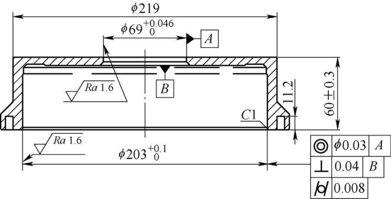
Figure 1 shows the brake drum. The material is HT250 and the wall thickness is 5.7-8mm. The surface roughness value of the inner hole is Ra=1.6 μm, and the cylindricity is 0.008 mm. After consulting the data.[1]The tolerance level of this cylinder is level 5, and it is difficult to batch process it on a CNC lathe.
Figure 1 Brake drum
3 Analysis of processing difficulties
1) For cast iron parts with hole diameter >200mm, even if they are not thin-walled parts, the cylindricity requirement of 0.008mm is not easy to meet. During mass processing, improper clamping can easily cause deformation, and the rationality of clamping directly affects the final flatness of the bearing surface, the circularity between the bearing surface and the chuck axis, and the false -round of the clamping part also affect the turning process. The stability and machining precision of the part. In the past, the clamp positioning steps were rotated on the universal claws. The claws are both clamping and supporting parts. Often due to damage to one of the claws, uneven clamping force or excessive clearance to the chuck, workpiece. is damaged. The lifting force prevents the workpiece mounting surface from fully fitting the claw positioning surface, causing positioning failure. When the claw steps are used as the positioning surface, because the steps are cut intermittently and have significant resistance to the tool, it is difficult to perform the three positioning steps at the same level by turning, which does not It is not conducive to guaranteeing the machining precision of the workpiece.
2) There is a groove with a width > 6mm and a depth > 11mm on the end face of the inner hole of the part, and the groove is very close to the working surface of the brake drum (hole of φ203 mm). and cutting force[2]This will further increase the difficulty of achieving the cylindricity of 0.008 mm.
3) The rigidity of the cutting tool and the heat and cutting force generated also have a negative impact on the cylindricity of 0.008 mm.
4) The rigidity of the machine tool and the uniformity of the finishing allowance also have a certain impact on the cylindricity.
To summarize, when processing this workpiece, a CNC vertical lathe should be used, and the deformation caused by clamping, cutting heat and cutting force should be controlled, and the processing process should be stable to meet the precision requirements.
4-part clamping solutions
Design a special fixture according to the structure and precision requirements of the room and install it as shown in Figure 2. The three support blocks and claws are evenly distributed alternately without interfering with each other. The top of the support block is connected to a support ring by threads. After installation, the upper end surface of the support ring is precisely rotated as the support surface of the workpiece to reduce clamping deformation and effectively avoid the impact on machining accuracy caused. by insufficient positioning support.

Figure 2 Special clamping device
5 Tool selection
Tool selection mainly considers the tool holder material, primary declination angle, secondary declination angle, blade rake angle, tool nose radius, width and angle of the chamfer, etc.
(1) Selection of tool holders. Common tool holders generally include steel tool holders, carbide tool holders and shock absorber tool holders. The hole diameter of this part is large and the required overhang of the toolbar is moderate. The steel toolbar is sufficient, and the toolbar does not need to have an internal cooling function.
(2) Insert selection Factors that have a greater impact on processing include material, cutting angle, tool tip radius and chamfer. In the processing of gray cast iron parts, PCBN blades and coated carbide blades are commonly used. PCBN blades are often used for finish machining of gray cast iron products because they can withstand high linear speeds and low affinity. line speed The speed will inevitably generate high cutting heat, which will affect the final quality of the thin-walled product. Therefore, it is better to use coated carbide insert to finish the φ203mm hole.
The main declination angle is the angle between the main cutting edge and the tool moving direction during the cutting process, which directly affects the tool life and vibration sensitivity. The secondary declination angle is the angle between the secondary; The cutting edge and the machined surface during the cutting process include the angle, if the secondary declination angle is too small, the precision of the machined surface will be destroyed; the cutting angle is the main angle of the cutting part of the tool, and a reasonable cutting angle can effectively reduce the cutting deformation of the workpiece; the roughness of the surface after treatment and the degree of sensitivity to vibrations.
Based on the above analysis of the tool, combined with the material to be processed, working conditions and other conditions, we finally selected a steel tool holder with an outer diameter of 50mm and an attack angle of 95° and a TNMG220408-KM blade. This blade is an equilateral triangular blade specially designed for processing cast iron. It can support high linear speeds. Associated with the tool holder, it provides a main deflection angle of 95°, a secondary deflection angle of 25° and an inclination of the edge. angle of 5°. The moderate main declination angle and negative declination angle make the tool life and machining accuracy reach very good expectations; the cutting angle of the tool is 0° and can be used on both the front and rear sides, which not only increases the number of tools available. tips, reduces costs, but also guarantees the resistance of the tool during processing; The tool tip radius of 0.8mm can effectively reduce the damage caused by cutting force and cutting heat on the workpiece while considering the strength.
6. Optimization of the process plan
1) There is a groove on one side of the inner hole of this part. If the inner hole is turned first and then the groove is turned, the cutting force will destroy the precision of the inner hole. Then the inner hole is machined, the internal stress after machining the groove will increase. Looseness will also destroy the accuracy of the bore after finishing.
2) The joint between the end face of the part and the inner hole requires 1mm × 45° chamfering. When finishing, if the machine tool first finishes the chamfering with a diagonal line, and then uses a straight line to finish the inner hole. , the X and Z axes of the machine will be synchronized during chamfering. The slight play caused by the oblique line will cause positioning to the inside diameter of the hole. There is a small deviation. This small deviation will be restored when processing the inner hole, which will affect the accuracy of the inner hole. If the inner hole is finished first and then chamfered, it will be due to the oblique extrusion of the tool. on the workpiece during chamfering. This affects the accuracy of the inner hole at the chamfer and is also not conducive to maintaining cylindricity.
To summarize, the final process plan is as follows: first semi-finish the inner hole and other surfaces, then finish the groove and make chamfers during the semi-finishing of the inner hole, and finally only process the hole. φ203 mm when finishing the inner hole. , no chamfering action is performed.
7. Selection of cutting parameters
1) Choosing a suitable tool does not completely guarantee batch processing of qualified products. Reasonable cutting parameters are also necessary to make the process controllable and stable. According to the reference linear speed vc of this coated carbide insert is 235 ~ 410 m/min, it is calculated that the maximum rotation speed when processing φ203 mm hole cannot exceed 643 rpm. The final rotation speed is 600 rpm, i.e. the linear speed is 382 m/min.
2) The surface roughness value Ra of the inner hole of this part cannot be greater than 1.6 μm, and the cylindricity tolerance level is level 5. After consulting the data[3]to guarantee this shape precision, the surface roughness value Ra must be controlled within the limits of 1.3 μm. According to the theoretical calculation formula of surface roughness, the feed amount f=0.09 mm/r can be obtained. In combination with the negative deflection angle of the tool, it will have a certain polishing effect and the feed amount f=0.11mm/r. r is finally determined.
3) According to the analysis of the overall geometric parameters of the blade, the cutting quantity of the inner hole of the workpiece for finishing turning cannot be less than 0.2mm, otherwise it will cause friction and burning of the workpiece. vibrating tool and tool, which is detrimental to the precision of the part and the life of the tool. He is finally determined at the end of filming. The quantity of rear knife ap=0.3 mm.
8Conclusion
Through the analysis of processing difficulties and process improvement, after CNC turning, the cylindricity of the φ203mm hole in the brake drum was measured with a cylindrical meter. Among the 50 continuously measured products, the cylindricity was all less than 0.006 mm (see Figure 3), which proves that the selection of machine tools, fixture design, process paths, tools and cutting parameters are reasonable and fully meet the machining precision of 0.008mm cylindricity requirements, the process is stable, and the consistency of dimensional and shape tolerances is very good.

Figure 3 Cylindricity test results
Daguang focuses on providing solutions such as precision CNC machining services (3-axis, 4-axis, 5-axis machining), CNC milling, 3D printing and rapid prototyping services.


