Mastering the Art of Metal Removal: A Deep Dive into Chip Control for Optimal Drilling Performance
The symphony of a well-executed drilling operation relies heavily on a critical yet often underestimated component: chip formation. Far from being mere waste, chips are vital indicators of process health, tool efficiency, and ultimately, the success of your machining venture. Understanding their formation, behavior, and how to control them is paramount for maximizing tool life, ensuring borehole quality, achieving efficient chip evacuation, and preventing costly downtime. Let’s dissect the anatomy and control of chips to transform your drilling operations.
1. The Blueprint of Efficiency: Decoding Chip Morphology and Size
The visual assessment of chips is your first diagnostic tool. Ideal chips for drilling are discrete, manageable segments. Look for:
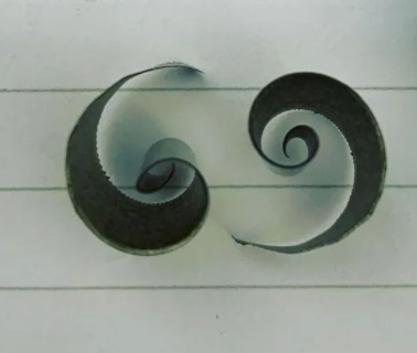
Preferred Shapes: "6" or "9" shaped chips, or compact cones ("C" shapes), are the gold standard. Their curled form minimizes bulk and facilitates smooth evacuation through flutes. Continuous, ribbon-like chips (especially long, straight strands) are a red flag, often indicating problematic material behavior or suboptimal tool geometry that demands immediate adjustment.
The Science of Size Control: Chip size hinges on two primary factors:
- Chip Breakers (Dividers): Engineered grooves or features on the cutting edge forcibly curl and fracture the chip. Wider chip breaker spacing generally produces larger, yet often more manageable curls. Modern drills integrate sophisticated chip breaker designs tailored to material groups.
- Edge Geometry: The rake angle and cutting edge preparation significantly influence how the chip deforms and breaks. High-positive rake angles promote tighter curling and easier fracture, but require careful balancing against edge strength. The geometry essentially acts as an internal chip control mechanism.
- Diameter Dynamics: Drill diameter also plays a role in natural chip breaking. Larger diameters inherently create greater speed differential between the inner and outer edges of the rotating chip (higher tangential velocity at the periphery). This shear gradient promotes twisting, tensile stress, and fracture – chips tend to break more readily with larger drills even without aggressive breakers. Conversely, small drills (<~8xD) face greater evacuation challenges, demanding more aggressive chip control features to overcome limited space.
2. The Critical Dimension: Chip Thickness & Material Interaction
Chip thickness isn’t arbitrary; it’s a function directly tied to your feed rate. Higher feeds produce thicker chips, while lighter feeds yield thinner chips. This dimension profoundly influences fracture mechanics and interacts dynamically with material properties:
- The Fracture Threshold: For many materials (like cast irons, harder steels), thicker chips are desirable. They experience higher strain concentrations, making them more likely to surpass the material’s elastic limit and fracture predictably. Forging that thick "C" shape is key.
- The "Gummy" Material Challenge: Conversely, low-strength, high-ductility "gummy" materials (e.g., soft low-carbon steels, 300-series stainless steel, pure titanium, aluminum alloys) behave differently. Their high plasticity makes them resistant to fracture. Thicker chips in these materials tend to deform plastically rather than break, leading to long, dangerous continuous ribbons that jam flutes and damage tools. Here, thinner chips achieved via lower feeds combined with sharp positive rakes and specialized chip breakers (like high backwall designs) are often necessary to induce segmentation.
- Shear Strain Rate – The Hidden Driver: The key metric linking feed, thickness, and material behavior is the Shear Strain Rate (SSR), defined as:
SSR = Deformed Chip Thickness / Undeformed Chip Thickness (Feed per Tooth)- Typical Steels: SSR ≈ 2-3:1
- Highly Ductile Materials: SSR ≈ 5-10:1+
A higher SSR signifies greater plastic deformation before separation. Materials with inherently high SSR (like the "gummy" alloys) require specific strategies to induce localized deformation sufficient for fracture.
3. The Unsung Hero: Coolant – Catalyst for Chip Control
Coolant isn’t just for temperature reduction; it’s an active agent in chip formation and evacuation. Its influence is multifaceted:
- Thermal Modification & Brittleness Induction: High-pressure coolant directed precisely at the cutting zone creates thermal shock on the hot, newly formed chip. For many susceptible materials (especially certain steels), this rapid quenching temporarily increases brittleness ("quench embrittlement"), making them far more prone to fracture just downstream from the cutting edge, even if they start as continuous ribbons.
- The Lifeline of Evacuation – Pressure vs. Volume:
- Pressure: Provides the "hydraulic force" to overcome friction and initiate chip movement up the flute, especially critical in smaller diameter drills with higher flow resistance.
- Volume: Determines the kinetic energy available to physically carry chips out of the deep hole. Insufficient volume results in chip re-cutting and packing. As drill diameter increases, achieving sufficient volumetric flow rate becomes paramount.
- The Non-Negotiable: Through-Tool Cooling: For deep-hole drilling (anything >5x diameter), internal coolant delivery isn’t a luxury; it’s essential. Benefits:
- Chip Evacuation: Provides consistent upward pressure directly behind the chip formation zone.
- Heat Extraction: Directly cools the most critical heat sources: the cutting edge/chip interface and the drill margin/wall interface (~40% of generated heat resides in the tool). Maintaining edge temperature is non-negotiable for wear resistance.
- Borehole Guidance: Acts as a hydraulic reference, helping maintain drill stability.
- Process Monitoring: Pressure fluctuations detected at the coolant pump can signal chip packing events long before catastrophic drill loading or breakage occurs.
The Coolant Evolution: Modern systems leverage variable pressure/volume control optimized for drill diameter and depth, often using programming algorithms that adjust pulsing frequencies for maximum evacuation efficiency.
4. Geometry as the Master Sculptor: Tool Selection Dictates Chip Form
When chips are suboptimal, the cutting tool geometry is often the first parameter to audit:
- The Razor’s Edge – Positive Rake: Increasing the rake angle reduces cutting forces and promotes tighter chip curl, generally enabling better chip formation and reducing contact zone friction/heat. However, higher positive rake inherently sacrifices edge strength (reduced tool cross-section).
- Shear Plane Angle (β) – The Efficiency Lever: This angle, formed within the primary shear zone (where the material yields and flows to form the chip), is the hidden link. Higher rake geometry increases β. The rule: A steeper β ≈ Better Chip Flow. Optimizing β involves balancing the rake angle against the material’s specific shear characteristics and deformation behavior.
(Integrate a simplified diagram showing primary shear zone angle (β) raked tool vs. conventional) - The Thickness Connection: Steeper shear planes also correlate with thinner chips for a given feed rate. Sharper tools inherently produce thinner, more manageable chips in tough materials. However, edge integrity must be preserved – advanced substrate/coatings allow pushing rakes higher safely.
- Beyond Rake: Consider the entire system: margin design to reduce heat build-up, specific corner chamfers or honing for fragile materials, flute geometry optimized for evacuation velocity for optimal chip flow dynamics without drag.
5. The Sentinel of Stability: Monitoring Chip Variation
Consistent chip formation signifies a stable process. Any change in chip appearance (shape, size, color, texture) acts as a crucial early warning system:
- Tell-Tale Indicators:
- Progressive Tool Wear: As edges dull, chips often become longer, more continuous, thicker at the root, hotter (shown by oxidation colors – blues/purples), or exhibit built-up edge fragments adhering to the chip underside.
- Workpiece Material Inconsistency: Hard inclusions in the workpiece material can cause sudden chip breakage leading to fine dust-like segments, or cause accelerated wear and subsequent chip change.
- Coolant System Failure: Loss of pressure/volume, contamination (tramp oil, bacteria), or incorrect concentration immediately manifests as poorer chip breaking and increased tendency for ribbon formation, especially in ductile materials. Chips may appear burnt or galled.
- Machine Instability/Vibration: Can lead to irregular chip segmentation or inconsistent thickness.
The Proactive Protocol: Initiate production runs with conservative parameters, analyzing chips from initial pilot holes. Treat chips as vital process data. Implement routine checks throughout long duration runs. Continuous monitoring via spindle power or coolant pressure sensors provides hard data to correlate with chip observation.
6. Why Chip Control Matters: Beyond Evacuation
Ignoring chip control risks:
- Catastrophic Tool Failure: Long, stringy chips jam flutes, causing extreme torque spikes, drill breakage, or catastrophic borehole damage. High-thrust forces generated by packed chips can shear indexable drill heads.
- Compromised Bore Quality: Chips dragged or recut by the drill point or margins create scratches, rough finishes, poor dimensional tolerances, and work hardening.
- Production Halt: Manual chip clearing, tool changes, scrapped parts, and spindle recovery lead to significant unplanned downtime and lost revenue.
- Reduced Tool Life: Poor chip evacuation traps heat and friction, accelerating flank wear, notch wear, and thermal cracking. Recutting chips accelerates tool degradation exponentially.
Conclusion: The Chip is King
Achieving the perfect chip – consistently segmented, optimally sized, and smoothly evacuated – is the hallmark of world-class drilling. It’s not happenstance but the result of meticulously understanding the interplay between:
- Intricate cutting tool geometry and chip breaker science.
- Precise optimization of feed rates to control chip thickness relative to material ductility.
- Masterful application of high-pressure, high-volume coolant leveraging thermal modification and powerful evacuation.
- Continuous vigilance, reading chips as process diagnostics.
By elevating chip analysis and control from an afterthought to a core competency, manufacturers unlock transformative gains in productivity, tool longevity, borehole quality, and overall operational reliability. Master your chips, and command your drilling process.


