Abstract: This paper derives the translation matrix and the rotation matrix in the form of homogeneous coordinates to mathematically model the position and attitude changes at any joint of the multi-axis linkage system. On the basis of the comparator component, the counter component and the generator component, a feedback form RTPA algorithm is constructed for actual control of the machining process of the multi-axis linkage CNC system, and the influence of frequency d The sampling is analyzed. Finally, an experimental study was carried out using the simulation processing of curved surfaces as an example. The experimental results show that under the control of the RTPA algorithm, the multi-axis linkage CNC system can effectively realize the processing of curved surfaces.
Keywords: multi-axis connection; CNC system; RTPA algorithm;
The level of integration and automation of the manufacturing industry has become an important criterion for measuring a country’s scientific and technological strength. Our country is a large manufacturing country, covering most categories of mechanical processing in the world. [1]in which CNC technology and CNC systems play a very important role. For various complex types of machining tasks, only CNC machining technologies and methods with more axis linkages can complete them more efficiently. [2]. Therefore, the design of multi-axis linkage CNC systems and multi-axis linkage CNC processing methods has become the essential content for judging the competitiveness of the mechanical processing and manufacturing industry. [3]. At present, there is a certain gap between my country and the advanced level of the development of 5-axis and above linkage CNC systems and CNC machining methods. This has also become a bottleneck limiting the in-depth development of my country’s mechanical processing. industry. To this end, this article takes the 5-axis linkage CNC system as the research object, and through mathematical model analysis and control process research, its specific application in curved surface processing is given.
1. Mathematical model of multi-axis CNC system posture
The key to realizing the control function and processing effect of a multi-axis CNC system lies in the accurate representation of position and attitude and reasonable dynamic connection. To this end, this paper first mathematically models the position and attitude of the multi-axis linkage CNC system as homogeneous coordinates.
The completion of a series of actions of the multi-axis linkage CNC machining system manifests in three-dimensional space as the cumulative effect of the rotational motion and translational motion of each joint and each axis. Therefore, to describe the multi-axis linkage CNC system from a mathematical point of view, we rely on the description of the rotation matrix and the translation matrix.
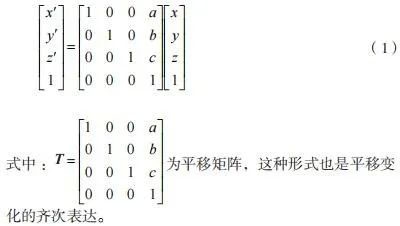
If a point A in space becomes the position of point A’ by translation transformation and it is translated by the units a, b and c on the three coordinate axes x, y and z, then there exists the formula following (1) The translation relationship indicated.
If a point A in space becomes the position of point A’ by rotation transformation and the angle with which it rotates about z is θ, then there exists a rotation relation as shown in formula (2).

In the same way, we can also obtain the rotation matrices of any point around the y axis and around the x axis, as well as the homogeneous expressions of these two matrices. By further extending this approach, it is possible to obtain the rotation matrix of any point around any axis in space, which will also be reflected in a combination of rotational movements around the x-axes, y and z. Once the translation matrix and the rotation matrix of the change in position of any point in space are obtained, a mathematical model of the change in position of that point can be established. This idea is also applicable to any coordinate system in space and any object in space. The multi-axis CNC machining process is the combined effect of the operating end undertaking the processing task and performing multiple translational and rotational movements around multiple axes.
Suppose that the position transformation of the end controller of the multi-axis linkage system is as shown in Figure 1. As shown in Figure 1, the end controller of the multi-axis linkage system has undergone a total of 2 transformations, one of which consists of two translation movements along the x-axis and the y-axis, and the other is a 90° rotation. around the z axis.

Figure 1 Position transformation of the final controller of the multi-axis linkage system
It can be seen that with the above modeling method, any joint and action of the multi-axis linkage system can be described by a combination of translational motion and rotational motion.
2. Process control of multi-axis CNC system
Once the multi-axis linkage CNC system can be described using mathematical models, the difficulty of the entire CNC process is to configure the CNC program so that the system executes the processing tasks according to the route established. This paper designs a pulse control algorithm with good real-time performance for the machining process of a multi-axis linkage CNC system, called Real time pulse algorithm (RTPA).
The CNC machining process is generally carried out and supplemented by interpolation algorithms, and the control of each axis in CNC machining is carried out based on the pulses of stepper motors, which requires the formation of a gap between the interpolation process and the pulse generation timing. corresponding relationship. However, the real-time performance of the traditional design of the pulse frequency-based interpolation process is not ideal. To this end, this paper designs a new pulse generation algorithm with better real-time performance from the perspective of VF (voltage-frequency) transformation algorithm. The pulse sequence generated by this algorithm can enable more efficient control of multi-axis linkage CNC systems.
This algorithm uses a comparator component, a counter component and a generator component to jointly generate a pulse sequence with good real-time performance. The block diagram of the algorithm is shown in Figure 2.

Figure 2 Block diagram of RTPA control algorithm for multi-axis linkage system
According to Figure 2, it can be seen that the displacement of a certain joint or end device of the multi-axis linkage system is sampled and used as the input of the RTPA algorithm, and the sampling frequency is f . Once the sampled displacement value is entered, it is compared to the pulse equivalent formed by the pulse counter on the feedback branch. The difference between the two is input to the pulse generator as a basis for judging the generation of the pulse sequence. The pulse generator will form 2 outputs, namely forward pulse and reverse pulse, which also correspond to the forward and reverse rotation of the stepper motor respectively.
The judgment of whether the pulse generator generates a forward pulse or a reverse pulse depends on the comparison between the cumulative error of the comparison of the input and feedback branches and the set threshold value (value). The comparison rules are as follows. Rule 1: If the sum of accumulated errors comparing the input and return branches is greater than the defined threshold value, the pulse generator generates a forward pulse and delivers it. Rule 2: If the sum of accumulated errors compared between the input and the feedback branch is less than the reciprocal of the set threshold value, the pulse generator generates an inverse pulse and outputs it.
The key parameter that determines the algorithm in this paper is also the sampling frequency f before the displacement is used as input. In order to determine the impact of the sampling frequency f on the performance of the RTPA algorithm, this paper sets the sampling frequency to 5 kHz and 20 kHz respectively, and draws its displacement response curve and its displacement curve. speed response. The results are presented in the figure. 3.

Figure 3 Effect of sampling frequency on the performance of the multi-axis linkage system algorithm
The left side of Figure 3(a) represents the displacement response curve of the RTPA algorithm when the sampling frequency is 5 kHz, and the right side represents the displacement response curve of the RTPA algorithm when the sampling frequency is 20 kHz; 3(b) shows the sampling frequency and speed response curve of RTPA algorithm when the sampling frequency is 20 kHz. The right side represents the speed response curve of the RTPA algorithm when the sampling frequency is 20 kHz.
It can be seen from Figure 3(a) that the higher the sampling frequency and the smaller the sampling period, the faster the moving response speed of the RTPA algorithm. From the comparison of the left and right figures, we can see that when the sampling frequency is 5 kHz, the displacement response of the RTPA algorithm takes 0.58 s, and the actual displacement of the multi-link system axes is consistent with the ideal displacement; when the sampling frequency is 20kHz, the displacement response of RTPA algorithm. After 0.16 s, the actual displacement of the multi-axis linkage system is consistent with the ideal displacement. This shows that the displacement response when the sampling frequency is 20 kHz is 0.42 s faster than the displacement response when the sampling frequency is 5 kHz.
It can be seen from Figure 3(b) that the higher the sampling frequency and the smaller the sampling period, the faster the response of the speed curve of the RTPA algorithm. From the comparison of the left and right figures, it can be seen that when the sampling frequency is 5 kHz, the speed response of the RTPA algorithm takes 0.5 s, and the actual speed of the multi-link system axes can be consistent with the ideal speed; when the sampling frequency is 20kHz, the RTPA algorithm after 0.13s speed response, the actual speed of the multi-axis linkage system conforms to the ideal speed. This shows that the speed response when the sampling frequency is 20 kHz is 0.37 s faster than the speed response when the sampling frequency is 5 kHz.
3. Surface machining simulation test of multi-axis CNC system
In the previous works, the position and attitude modeling and RTPA control algorithm design were carried out for the multi-axis linkage CNC system, and the effective control strategy of the multi-link CNC system -axes was determined through the impact analysis of key parameters. Then, a simulation test will be carried out to verify the control performance of the RTPA algorithm of the multi-axis linkage system proposed in this paper. The simulation test selects curved surface processing as the processing object of the multi-axis linkage CNC system. Curved surfaces present a certain degree of complexity in various processing units and require relatively sophisticated control algorithms. The processing of the entire curved surface is completed by a continuous curve processing path. The simulation results of the surface to be treated in this article are shown in Figure 4.

Figure 4 Simulation results of the surface to be treated in this article
As shown in Figure 4, the curved surface to be treated in this article is a curved surface section which forms an axial width in the x direction and a radial width in the y direction. The radius of curvature of the curved surface. is located in the direction of the z axis. Figure 4 also shows the initial position of the tool, i.e., the starting point, and the parallel curves on the surface indicate the machining trajectory under the control of the RTPA algorithm.
There are many CNC machining methods for curved surfaces, such as machining route method based on trajectory generation parameters, section data processing route method based on CC paths and the path-based section machining route method. This article chooses the cross-section data processing method based on CC path and combines it with Z-shaped cutting to complete the processing. During the machining process, the control effect of the displacement and speed curves obtained by the RTPA algorithm in the x-axis direction, y-axis direction and z-axis direction is shown in Figure 5.

Figure 5 Control effect of RTPA algorithm on displacement and velocity curves in three directions
As shown in Figure 5(a), the displacement control by RTPA algorithm in the x-axis direction forms a triangular wave curve. Limited by processing tasks, the maximum displacement value of RTPA algorithm in the x-axis direction is 0mm, the minimum value is close to -150mm, and the triangular wave period of the curve displacement is 4.17 s. The RTPA algorithm controls the speed in the x-axis direction to form a rectangular square wave curve shape, but there is some instability due to the influence of the machining process. The maximum speed of the RTPA algorithm in the x-axis direction is close to 80 mm/s, the minimum value is close to -80 mm/s, and the rectangular square wave period of the speed curve is 4.17 sec. As shown in Figure 5(b), the RTPA algorithm’s displacement control in the y-axis direction forms the curve of a step wave. Limited by processing tasks, the maximum displacement value of RTPA algorithm in the y-axis direction is 0mm, the minimum value is close to -6mm, and the step wave period of the curve of displacement is 4.17 s. The RTPA algorithm controls the speed in the y-axis direction as a pulse wave. The maximum speed of the RTPA algorithm in the y-axis direction is 0 mm/s, the minimum value is -10 mm/s, and the rectangular square wave period of the speed curve is 4, 17 sec.
As shown in Figure 5(c), the displacement control by RTPA algorithm in the z-axis direction forms a half-wave sinusoidal curve. Limited by the processing task, the maximum displacement value of RTPA algorithm in the z-axis direction is 6.2mm, the minimum value is 0mm, and the sine half-wave period of the curve of displacement is 2.08 s. The RTPA algorithm controls the speed in the z-axis direction to form a sawtooth wave curve. The maximum speed of the RTPA algorithm in the z-axis direction is close to 15 mm/s, the minimum value is close to -15 mm/s, and the sawtooth wave period of the speed curve is 2.08 s.
4. Conclusion
This paper studies the multi-axis linkage CNC system. First, in the form of homogeneous coordinates, the position and attitude changes at any joint of the multi-axis linkage system are mathematically modeled, and the process of generating the translation matrix and the matrix rotation is deducted. Secondly, an RTPA algorithm in the form of feedback is constructed on the basis of the comparator component, the counter component and the generator component, which are used for actual control in the machining process of the multi-axis linkage CNC system, and the The impact of the sampling frequency is analyzed. Finally, a verification test was carried out using the curved surface simulation processing as an example. The test results show that the CC path-based cross-section data processing method used in this paper, combined with the feed of a Z-shaped tool, can successfully complete the process. treatment. At the same time, the RTPA algorithm effectively controls the displacement and speed in the three coordinate axes.
Daguang focuses on providing solutions such as precision CNC machining services (3-axis, 4-axis, 5-axis machining), CNC milling, 3D printing and rapid prototyping services.


