1 Preface
The cover is usually used as a seal. Before assembly, it must undergo air, water and other pressure tests to ensure that the product will not leak and ensure the airtightness of its assembly and use. Most of them are integral castings or welded parts. complex shapes and multiple structures. Variable, different sizes, cavity-shaped interior, thin and uneven walls. In production and manufacturing, there are not only hole systems, sealing grooves and planes that require high precision, but also many special-shaped fillets, bosses and irregular curved surfaces, which are difficult to process and to manufacture.[1]。
2 Parts structure and process analysis
2.1 Analysis of the structure of the parts
The cover is a box type part. It is a semi-closed polyhedron with uneven cavities and interior walls and mainly irregular structures. It is mainly used to ensure the cleanliness of the bodywork and reduce the noise generated by the bodywork during work. at the same time, it can play a role in beautifying the appearance. In mechanical processing, there are many processing elements, large processing volume and irregular structures, resulting in complex processes.[2]。
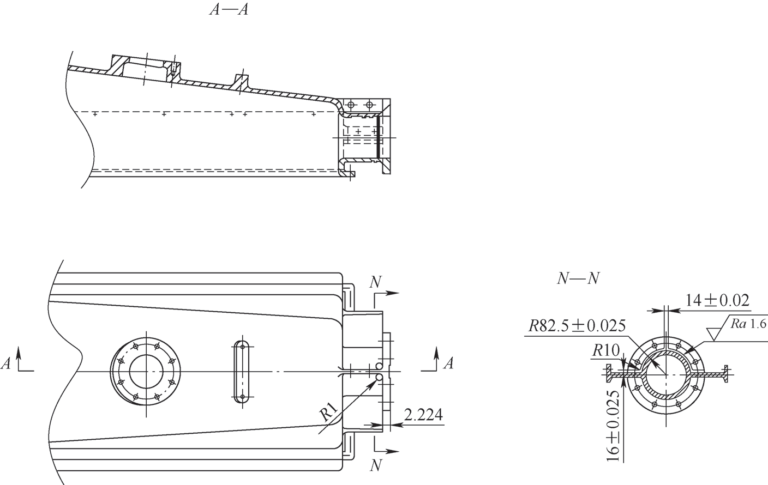
Figure 1 Covering process requirements
2.2 Process analysis
Coverage: The blank is a solid cast iron part with strict surface quality requirements, the material is difficult to process, the tool wears quickly, and it is difficult to process spatial curved surfaces. The cover parts are shown in Figure 1. There are left and right arcs on the back of the flange, separated by 14mm ribs in the middle. The left and right sides are symmetrical structures, with left side edges on the upper and lower sides. The surface roughness value Ra = 1.6 μm.
2.3 Analysis of difficulties
The lid is a box type piece. QT400-15 material is ductile iron, which has high strength and good toughness. It has the characteristics of wear resistance, vibration absorption and oxidation resistance, but its cutting performance is poor. According to the drawing requirements, the back side of the connection flange must be fully processed. The arches are distributed symmetrically to the left and right, separated by ribs in the middle. The arc surface is processed perpendicular to the tool axis. When processing the curved surface, the geometric dimensions of the tool must be adapted to the tool path of the surface. to ensure that the shape of the final curved surface meets the process requirements. As shown in Figure 1, the thickness of the rib plate is (16 ± 0.025) mm, (14 ± 0.02) mm, and the root fillet R (82.5 ± 0.025) mm. The processing precision is high and the surface quality requirements are. strict. Since the back of the flange is separated by ribs, it will interfere with the use of a three-sided milling cutter or lathe and cannot be processed.[3]。
3 Process flow and method of CNC machining
3.1 Processing methods
Although the arc surface of this part is a surface of revolution, its shape and structure are box-type parts (see Figure 2), so it is not suitable for turning machine tools. The rear face of the flange is separated by three ribs, with a rounded root transition. The back and front faces require high dimensional accuracy and surface roughness and can be processed on three-axis and multi-axis milling machines. In multi-axis machining, since the mutual positions of tool and workpiece change at any time during processing, all processing can be carried out in one clamping to achieve optimal processing conditions. However, its purchase cost and software cost are much higher than those of the three axes, the maintenance and upkeep costs are too high, and the requirements for operators’ operational skills are also high, resulting in high labor costs. In the three-axis machine tool, the tool axis vector remains unchanged, and the processing is carried out in the normal plane of the Z axis. Using linkage adjustment can complete the processing of the spatial surface and obtain better rigidity of the system. Since this product is manufactured in large quantities and small batches, there is no need for custom tooling. The production needs of this product can be met by using existing same-height universal pads and downward pressure plates for positioning and clamping. After on-site measurement of the milling head of the machine tool and analysis of the processing factors of the housing, a ball milling cutter can be used to create a curved surface fillet in the ZY plane along the axis direction Z in order to obtain a better surface. processing precision, quality and efficiency. And the best quality/price ratio.

Figure 2 Blank cover
3.2 Concept of tool
Tool selection and determination of cutting quantity are important elements in CNC machining technology. They not only affect the processing efficiency of CNC machine tools, but also directly affect the processing quality, and at the same time change the entire processing cost. In combination with the machine tool characteristics, workpiece material performance, clamping and process requirements, three-sided milling cutters, end mills and ball end mills are selected for processing. Since the three rib sections on the back of the flange are evenly spaced at 90°, there is plenty of residue at the root of the ribs when back milling with a three-sided edge mill, and the The whole process can be processed along the arc direction with the side edge of the end mill. The root arc surface is a three-dimensional surface formed from bottom to top. A ball-tipped tool with a radius less than or equal to the minimum radius of curvature of the surface should be used for interpolation milling. It is measured that the margin of 6mm on one side of the blank is large. In order to ensure rigidity and processing efficiency, the specifications shown in Figure 3 are φ20mm × 80mm × 150mm × 4F (YT) and R10mm × 80mm × 150mm. (YT) ball nose milling cutter knife.

Figure 3 End mill (bottom) and ball mill (top)
3.3 Cutting plane
In the cutting process, according to the actual processing conditions of the workpiece, in order to ensure the accuracy and roughness of the rounded curved surface, uphill milling is used from bottom to top. Separate tool start points and tool set points. In order to ensure safety, the starting point of the tool should be as close as possible to the workpiece to reduce the movement of the tool without load, shorten the feed path and save time. execution during the machining process. Since the blank margin is large, the cyclic processing method should be used to mill in order as shown in Figure 4. The margin should be gradually removed in the YZ direction, leaving a margin of 0.2mm for the finish. During this period it must be deleted. noted that the feed and retract points must be perpendicular to In the Z axis direction, the feed speed cannot be “G0”, and the “G0” command must avoid that “Y, Z ” does not move at the same time.
The tool cutting parameters are selected: φ20 mm end mill. The tool material supports linear speed vc of 90 ~ 120 m/min, back cutting quantity ap of 0.3 ~ 2 mm and feed fz of 0.07 ~ 0.3 mm/z.
R10mm × 80mm × 150mm ball end mill (YT), tool material supports vc linear speed of 120~150m/min, ap back engagement of 0.3~0.8mm and a feed fz of 0.11 ~ 0.18 mm/z.
Since the blank is a solid casting, affected by the casting process, the surface of the blank may sometimes have hard spots, pores and sand inclusions. In order to reduce quality risks and ensure cutting stability, after debugging and checking the specimen, the final cutting parameters of the φ20mm end mill were selected as vc=92m/ min, n=1465r/min, ap=1.5mm, fz. =0.0 7 mm/z, vf=410 mm/min; The cutting parameters of R10mm ball end mill are selected as vc=130m/min, n=2070r/min, ap=0.5mm, vf=228mm/min. After processing 12 pieces per batch, using the above cutting parameters, the processing quality and stability are good, and the tool is durable.

Figure 4: Toolpath
3.4 Programming
According to the geometric dimensions of the workpiece drawing, the operating trajectory data of the tool center is calculated. Since the arc surface is in the YZ plane, when using a spherical milling cutter, it is necessary to calculate the coordinates of the contact point and complete the R82.5mm arc milling by approximation of the point. The ultimate goal of digital calculation is to obtain all relevant position coordinate data needed for programming. Calculate the values of coordinates Y and Z using trigonometric functions according to Figure 5: Y=Rcosα, Z=Rsinα.

Figure 5 Principle of calculating coordinates
When programming the Heidenhain CNC program, set Q1=17 as the start angle, Q2=0.1 as the angle increment, Q3=+76.5 as the end angle, Q4=92.5 (R=82.5 +10) as arc radius, Q1= Q1 + Q2 adds a variable for the angle. Once the program is compiled, its operation must be verified before it is officially used for production and processing. In special cases, a machining test inspection of the parts is also required. According to the inspection results, the program is modified and adjusted, and it is often repeated several times until a program that fully meets the processing requirements is obtained.
56 “D20-QTD” TOOL CALL Z S500
57L Z+100 R0 FMAX
58L X-50 Y-150 R0 FMAX
59L Z+26R0 FMAX
60 L X+32 R0 F1000
61 L Y-88.771
62 FN 0:Q1 =+17 ;
63 FN 0:Q2 =+0.1; angle increment
64 FN 0:Q3 =+76.5;
65 FN 0:Q4 =+92.5; arc radius
66FN0:Q5 =+0
67FN0:Q6 =+0
68 LBL.2
69 Q1=Q1+Q2 ; angle increases variable
70 Q5=Q4×COS Q1; loop calculation of Y value
71Q6=Q4×SIN Q1; loop calculation of Z value
72 L Y-Q5 Z+Q6 R0 F1000
73 FN 12: IF+Q1LT+Q3 GOTO LBL 2;
74L Y-21Z+90.085
75L Z+100 FMAX; knife retraction
76M0
4 Debugging, processing and inspection
The origin of surface fillet processing in the program is the center of the flange, that is, X0, Y0 and Z0 in G54 are on the upper surface of the flange. After using the edge finder to center in the X and Y directions, enter the mechanical coordinates into the corresponding G54. After the Z direction chuck or reference knife fits the outer circle of the flange, calculate the Z value and input it into G54. Before processing, let the machine tool run dry to check the correctness of the tool movement path. During debugging, the spindle speed and feed during processing can be appropriately adjusted according to the actual situation (see Figure 6 for the processing process) to achieve the best cutting performance. After the first part is completed, it is sent to a three-coordinate measuring instrument to measure linear dimensions, geometric tolerances and surface roughness. Test results meet process requirements.

Figure 6 Processing surface fillets
5Conclusion
Through the special use of ball milling cutters, after many attempts and tests, the process plan of the cover surface processing was finally determined, successfully solving the problem of difficult processing of the arc surface of lid space, many processing elements, high quality. processing accuracy and surface roughness. Strict requirements and other difficult issues. It guarantees the precision of blanket processing, improves the controllability and stability of processing quality, and ultimately forms mass production capabilities. At the same time, this method is widely feasible and can provide help and reference for similar surface treatment applications.
Daguang focuses on providing solutions such as precision CNC machining services (3-axis, 4-axis, 5-axis machining), CNC milling, 3D printing and rapid prototyping services.


