Conduct design and optimization research on the investment casting process of aluminum alloy automobile steering knuckle to obtain a qualified investment casting process solution for the steering knuckle aluminum alloy automobile. Methods Combining the structural characteristics, casting material properties and casting experience of aluminum alloy steering knuckle castings, an inner door was opened in the main part and gooseneck of the part steering knuckle casting, and the initial casting pattern of the aluminum alloy steering knuckle was designed; Through the initial process flowsheet, feed risers are installed in areas with serious casting defects, and additional feeders are added to the top of the castings. The optimized casting pattern of the aluminum alloy steering knuckle was achieved through the implementation of an exhaust channel and other measures. Based on ProCAST software, a finite element model of two casting schemes of investment casting of aluminum alloy steering knuckle was established to analyze the filling process. of the investment casting of the aluminum alloy steering knuckle, the solidification process and shrinkage and porosity characteristics were simulated and analyzed numerically. Results: The filling process of the initial casting pattern of the aluminum alloy steering knuckle casting was relatively stable and smooth. The casting formed an isolated liquid phase area during the solidification process, after complete solidification, there was shrinkage over a large area. cavity defect in the central part of the molded part. Optimizing the casting pattern can control the flow, filling sequence, and solidification characteristics of the molten metal. The entire solidification process of the casting is basically symmetrically distributed in the middle. inside the feed riser, and the maximum shrinkage rate is controlled below 2%. Conclusion The design of the optimized casting scheme is reasonable and efficient, and can effectively eliminate the defects of aluminum alloy steering knuckle castings.
Keywords: aluminum alloy; steering knuckle; investment casting; molding process design;
As global environmental protection requirements continue to increase, vehicle emission standards and energy efficiency requirements are becoming more stringent.[1]. Many studies have shown that the fuel consumption of an automobile is linked to its own weight and that lightweighting automobiles plays an important role in reducing fuel consumption.[2-5]. The development and use of alloy materials with low density, high strength and excellent performance to replace original automobile parts is one of the effective ways to lighten parts.[6]. Compared with traditional materials, aluminum alloys are widely used in the automobile industry due to their excellent specific strength, low density, excellent plasticity/thermal conductivity and excellent corrosion resistance.[7-10]. As an essential component of the automobile steering system, the automobile steering knuckle takes on the important task of maintaining stable driving of the car and quickly transmitting driving direction. Many domestic and foreign researchers have carried out relevant research on the forming process of aluminum alloy automobile steering knuckles.[11]Taking the A356 aluminum alloy steering knuckle as the research object, the differential pressure casting process parameters were studied by combining numerical simulation and optimization algorithms, and intelligent algorithms were used to obtain the optimal process combination parameters. Luo Yang et al.[12]The gravity casting process of aluminum alloy automobile steering knuckles has been optimized and studied. Measures such as placing reasonable sprues, risers and using thermal insulation sleeves were adopted to achieve sequential solidification of the castings and virtually no defects inside the castings. Luo Jixiang and others[13]The extrusion casting process of aluminum alloy steering knuckles was studied, and the characteristics of horizontal and vertical extrusion casting machines were compared and analyzed. The results showed that using horizontal machines to produce steering knuckles requires conformal cooling of the thick parts of the castings to eliminate problems. Shrinkage cavities and shrinkage porosity defects, steering knuckles produced with vertical machines have more advantages. The mechanical properties of castings are uniform, but defects such as slag inclusions and pores are easily formed. Chen et al.[14]Based on the structural simulation and optimization design of the casting process, by controlling all processes of the semi-solid die casting process, a high-performance aluminum alloy steering knuckle was obtained. Das et al.[15]The rheological die casting process of A356 aluminum alloy was studied, and the optimal position, temperature and casting conditions were determined by numerical simulation, and an aluminum alloy steering knuckle with ideal microstructure and mechanical properties were obtained. The research of many researchers mainly focuses on the design and optimization of the die casting and sand casting process of aluminum alloy steering knuckles, but there are few researches on the precision forming process Aluminum alloy steering knuckles. On this basis, this article takes a certain type of automobile aluminum alloy steering knuckle as a research object to study and explore its aluminum alloy steering knuckle investment casting process, so as to provide a benchmark for precision casting process and light weight of automotive aluminum alloy steering knuckle. design.
01
Casting process analysis and initial layout design
1.1 Casting process
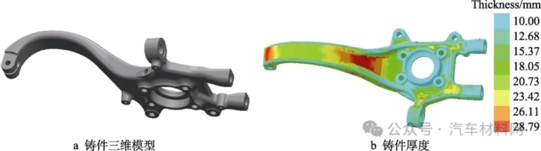
The three-dimensional model of the automobile steering knuckle casting is shown in Figure 1a. The basic outline size is 600mm × 275mm × 163mm. It is mainly composed of two parts, the gooseneck and the main body, and integrates various parts. structures such as shafts, sleeves and forks. The main body includes key components such as swing arms and connecting rods. It has many precision holes of different sizes on its surface. The structure is complex and the cross section of each part changes significantly. The swan neck is the connecting part of the steering knuckle, used to connect the steering rod and the steering wheel, and is responsible for transmitting the steering force applied by the driver. Therefore, this part is thick and large, with a simple structure, but its. the cross-sectional area is large. The thickness of the steering knuckle casting is shown in Figure 1b. The thickest part of the casting is located at the connection between the gooseneck and the main body. Generally speaking, the thickness of the overall steering knuckle structure is about 29mm. the molding is complex and uneven. This is a large, complex structural casting. In the process, the probability of formation of defects such as shrinkage cavities and the difficulty of post-processing of ingate should be fully considered in the design.
The material of automobile steering knuckle is A356 aluminum alloy. This aluminum alloy has excellent liquid fluidity, density of 2680 kg/m3, solidus temperature of 561℃ and liquidus temperature of 616℃ when casting castings with complex geometry. shapes, it has excellent filling effect and low solidification shrinkage, which can effectively avoid defects in casting parts during the solidification process.[16-17]。
Figure 1 Three-dimensional model and thickness analysis of castings
Fig.1 Three-dimensional model and thickness analysis of castings: a) three-dimensional model of castings; b) thickness of castings
1.2 Initial design of the casting plan
Since there are a large number of blind holes and through holes in the main body of the automobile steering knuckle casting, the flow resistance of the molten metal is large during the filling process, and the wall thickness of this part is very different, and the cross-section has many sudden changes, so it is easy to form shrinkage cavities inside the casting part, inclusions, cracks, casting insufficient and other defects.[18]. At the same time, since the flow path of the molten metal flowing through the swan neck of the casting is long, there is a long-term heat exchange between the surface layer of the casting liquid and the casting liquid. mold shell, causing the temperature of the molten metal in the contact part to drop faster than that of the inner layer, easily causing surface defects such as membrane, inclusions, cold insulation, etc.[19]。
Based on the characteristics of A356 high-strength cast aluminum alloy, combined with the structural characteristics and casting experience of automobile steering knuckle castings, the initial casting scheme of the parts Cast aluminum alloy steering knuckle is obtained, as shown in Figure 2a. The initial casting system adopts a top casting design, which has a simple structure and strong mold filling capacity. In theory, it can reduce the likelihood of casting defects. In addition, an interior channel is provided at the swan neck and the main body. which can reduce cold shutdown and poor pouring of the casting. To ensure that the temperature of the upper half of the casting is higher than the temperature of the lower half after filling, this also promotes the bottom-up solidification sequence. of the entire casting, making it easier to cut and clean the inner channel during post-processing. Import the casting model with the gate system into ProCAST software and divide it into meshes. The mesh value is 5 mm. The finite element mesh is automatically generated. The total number of surface meshes generated is 43,850 and the total number of volume meshes. is 217,473. , the finite element model of the casting system of the initial process is shown in Figure 2b.
02
Numerical simulation and analysis of the results of the initial plan
2.1 Setting up the digital simulation
ProCAST software is used to digitally simulate the castings and the following parameters are set for the casting-related process parameters: The casting temperature of aluminum alloy is typically about 100°C higher than the casting temperature. of liquidus, so the casting temperature in this article is 700°C. °C and the shell preheating temperature is set at 400 °C, the total pouring time is controlled at about 5s.[20]. The heat exchange coefficient between the mold shell and the door system, the mold shell and the molded part is 900 W/(m2·K)[21]. The natural cooling method is adopted, the heat exchange coefficient between the shell and the air is set to 10W/(m2·K), and the default ambient temperature is 20℃.
2.2 Simulation results and analysis
2.2.1 Filling process
The process of filling the initial casting plane is shown in Figure 3. It was observed that at the beginning of mold filling, the molten metal entered the mold cavity from two channels at the same time and the speed filling of the mold was low and uniform. When the mold filling rate was 50%, the flow rate was. the molten metal in the mold cavity could reach up to 0.93 m/s, no obvious splashing occurred. In the middle and late stages of filling, the gooseneck is gradually filled from the outer end to the inside, and there is a slight air entrainment phenomenon. The whole mold filling process is relatively stable and smooth, the temperature of the molten metal is higher than its liquidus temperature, there is no cold shutdown or insufficient pouring, and the mold filling can be carried out gently.

Figure 2 Initial casting plan and finite element model
Fig.2 Initial casting diagram and finite element model of the castings: a) initial casting diagram; b) finite element model

Figure 3 Simulation of the filling process
Fig.3 Simulation of the filling process: a) filling to 30%; b) 50% filling; c) 90% filling
The completion time of filling each part of the steering knuckle casting is shown in Figure 4. It can be seen that the liquid level increases in different areas of the casting at different heights. The gooseneck takes the longest to fill the mold, while the main part fills more slowly. This phenomenon occurs because the main part of the casting is large in size and complex in shape, while the gooseneck is relatively small in size and simple in structure, and the mold filling speed is fast. At the same time, since the molten metal flows from the right inlet to the bottom of the impact cavity and goes to both sides, finally causing part of the molten metal to be poured into the top of the gooseneck preferably, so that the area near the top of the gooseneck is filled first.

Figure 4 Filling time for each part of the casting
Fig.4 Filling time of each casting
2.2.2 Solidification process
The solidification process of the knuckle casting is shown in Figure 5. As shown in Figure 5a, the total time spent in the solidification process is 2057.5 s, at the beginning of solidification, the top of the gooseneck and the protruding area of the main body begin to solidify first. The gooseneck and the main body as a whole solidify sequentially from the outside to the inside. both sides solidify near the inner sprue, the trigger system has not started to solidify, This solidification sequence is conducive to the solidification and forming of parts other than the two inner doors of the casting part. The part of the casting located between the two inner doors is solidified after the casting system solidifies. This part is subject to insulation due to solidification. loss of power function of the casting system. The final solidification zone is located at the junction of the two parts, as shown in Figure 5b. There is a high probability that shrinkages and shrinkage cavities will form at this location.
2.2.3 Defect prediction
During the solidification process of the casting, the surface of the casting first solidifies to form a hard shell on the surface. As the solidification process progresses, the inner door is closed. At this time, the solid shrinkage of the casting shell is less than the shrinkage of the molten metal in the casting shell. The solidification shrinkage is therefore not completed by the external metallic liquid. a space forms between the surface layer of the casting and the internal liquid metal. A certain degree of vacuum eventually forms shrinkage and cavity defects.[22-23]. According to the porosity criterion, the location and probability of shrinkage defects in castings can be determined.[24]. The expected distribution of shrinkage porosity inside the casting is shown in Figure 6. There is a large area of shrinkage porosity defects at the connection between the gooseneck and the main body of the casting. casting of the steering knuckle. This is consistent with the results of the analysis. of the solidification process above. Another location The defect is located on the channel, and the channel is removed during post-processing without affecting the quality of the casting.

Figure 5 Simulation of the casting solidification process
Fig.5 Simulation of the solidification process of the molded parts: a) solidification time of each molded part; b) final solidification zone

Figure 6 Prediction of casting defects
Fig.6 Prediction of casting defects
03
Numerical simulation and analysis of the results of the optimization plan
3.1 Optimize the casting plan design
The design quality of the door system is closely related to the forming quality of the casting.[25]. Through the analysis of the initial casting plan, it was found that the main reason for the shrinkage cavity in the casting part is that the connection between the gooseneck and the main body is far from the inner door, and the interior door solidifies before that. , so the disbursement system cannot supply in time. Based on the above analysis, the initial casting process plan was reasonably optimized, and feed risers were installed in the areas with serious casting defects in the initial process plan in order to improve the power performance of the door system. In order to achieve the sequential solidification effect, the size of the designed riser is 83mm × 70mm × 80mm, of which the riser neck size is 40mm × 20mm × 8mm. At the same time, two exhaust channels with a diameter of 10mm are added at the top of the casting to reduce the filling resistance and ensure the filling quality of the casting. The optimized casting plan is shown in Figure 7.

Figure 7 Optimized casting plane design
Fig.7 Optimized casting pattern design
3.2 Simulation results and analysis
When the initial process parameters and boundary conditions remain unchanged, the optimized model is imported into ProCAST for solution. The filling process is shown in Figure 8. It can be seen from the mold filling process that the liquid level in each area of the casting is basically the same, and the flow of molten metal is relatively smooth, which is conducive to the formation of castings with good surface quality, see Figure 8a. The situation of air entrapment in the casting is shown in Figure 8b, where the dark area represents gas. It can be seen that there is no gas in the casting, which indicates that there is no air trapped inside the casting cavity, which indicates that the exhaust of. this process is good. Slag inclusions in castings are shown in Figure 8c. During the mold filling process, as the molten metal flows into the mold cavity, the slag inclusions float on top of the molten metal. At the end of the mold filling period, the slag inclusions are transported away. by molten metal in the riser and exhaust stem. Avoid defects of slag inclusion inside or on the surface of castings.
The solidification process of the optimized casting plane is shown in Figure 9. It can be seen from Figure 9a that the casting solidifies sequentially from both ends to the central connection during the whole solidification process, showing symmetry. The inner channel connection part and the casting solidify almost at the same time, and the feed riser solidifies. Finally, indicating that the feed riser and inner channel can exert a certain feeding effect. It can be seen from Figure 9b that once the casting has solidified as a whole, the feed riser is not yet completely solidified. This solidification sequence is conducive to the supply function of the riser.
Predict the shrinkage and porosity conditions of the optimized casting pattern. Figure 10a shows the total shrinkage rate of the casting when the density is 98%. The simulation results show that there is no shrinkage porosity defect inside the casting part. defects are concentrated in the repair. Shrink the inside of the riser. Figure 10b is a cross-sectional view of the casting in the xy direction. It can be seen that the faultless position is located in the center of the feed riser, indicating that the molten metal in this area is delayed until final solidification, ensuring that the solidification removal of the faulty position The original casting contains sufficient molten metal to feed without defects.

Figure 8 Optimized casting plane filling process
Fig.8 Filling process of the optimized casting scheme: a) the filling time of each part; b) prediction of gas trapping; c) prediction of slag inclusion

Figure 9 Optimized casting plane solidification process
Fig.9 Solidification process of the optimized casting scheme: a) solidification time of each casting; b) final solidification zone

Figure 10 Prediction of casting defects with an optimized casting scheme
Fig.10 Prediction of casting defects from an optimized casting scheme: a) shrinkage porosity of castings; b) xy section diagram
04
in conclusion
By combining the structural characteristics of aluminum alloy steering knuckle castings, casting material properties and casting experience, the rational design of feed risers and door opening can effectively reduce the probability of fault formation. By adding feed risers in areas with significant shrinkage and shrinkage holes in the initial process plan, an optimized pour plan was designed. The simulation analysis revealed that the casting of the aluminum alloy steering knuckle using the optimized casting plane showed stable performance during the whole solidification process. Both ends of the casting tend to solidify layer by layer towards the middle. Defects mainly form in the access system and riser parts. The shrinkage and shrinkage rate of the steering knuckle casting are controlled below 2%, which meets actual production requirements. Precision casting aluminum alloy steering knuckle.
Daguang focuses on providing solutions such as precision CNC machining services (3-axis, 4-axis, 5-axis machining), CNC milling, 3D printing and rapid prototyping services.


