127 Sets Processing 4000mm 127 Sets High-Precision CNC Lathes
15 Years of Experience

CNC Knowledge: Thin-walled ring and lug low-rigidity composite component processing technology

Considering the problem that typical low-stiffness components of thin-walled ring-and-lug composites are prone to instability during processing, process analysis and improvement were carried out through a process reference conversion control, part stiffness reduction treatment, stiffness reinforcement and vibration absorption composite. , and equipment to maximize surface area and rigidity. Clamping and many other improvement measures […]

cnc knowledge: thin walled ring and lug low rigidity composite component processing

Considering the problem that typical low-stiffness components of thin-walled ring-and-lug composites are prone to instability during processing, process analysis and improvement were carried out through a process reference conversion control, part stiffness reduction treatment, stiffness reinforcement and vibration absorption composite. , and equipment to maximize surface area and rigidity. Clamping and many other improvement measures were implemented to achieve stable treatment.


1 Preface

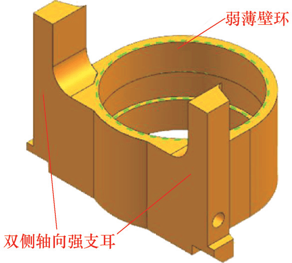
A typical composite structure of thin-walled weak ring and bilateral strong axial lugs is shown in Figure 1. The material of the parts is 30CrMnSiA steel conforming to GJB 1951-94 standard, and the quenched hardness is 30~35HRC. The surface roughness value of the workpiece is Ra=3.2 μm, the symmetry of the two ears is 0.05 mm, and the verticality of the bottom surface is 0.05 mm. Processing requirements are high. The wall thickness of the ring body is 2mm, the ring wall is too thin and the rigidity is insufficient. The main body of the workpiece has a low rigidity structure and is prone to instability during machining, especially when machining the outer wall of the ring and clamping thin-walled rings.[1,2]。

Figure 1 Typical composite structure of a weak, thin-walled ring and axially strong bilateral ears


2 Treatment analysis

Use of general machining technology[3-5]The morphology of the typical composite structure product processed with weak thin-walled ring and axially strong bilateral legs is shown in Figure 2. It has the following disadvantages.

1) There are obvious traces of knife connection in the middle of the bilateral axial legs. The upper and lower parts of the bilateral axial support legs are formed in two steps: milling the shape of the thin-walled ring and milling the shape of the bilateral axial support legs respectively. Since the process zero points of the two working steps do not coincide, obvious tool connection marks appear in the middle of the axial legs on both sides.

2) The thin-walled ring has obvious vibration marks in the middle of the shape. The wall thickness of the middle part of the ring body is 2mm, and the rigidity is obviously insufficient. When processing the thin-walled ring shape, the middle part is prone to instability and obvious vibration marks will occur. When the above problems overlap, the problem of easy processing instability becomes a production bottleneck.
Image WeChat_20241009104035.png

Figure 2 Cut marks and vibration mark defects


3 Process optimization

Considering the shortcomings of general machining technology, composite processing measures such as “inner hole end face contour” process reference conversion control, the gradual reduction of workpiece rigidity processing , the combination of stiffness strengthening and vibration damping and absorption, and clamping to maximize the surface area and rigidity are adopted to achieve the steady-state processing goal of the composite structure d ‘a weak thin-walled ring and legs bilateral strong axials. Based on the technical analysis and ideas above, the process optimization process[6-8]As shown in Figure 3.

1728441763982862.png

Figure 3 Processing process of composite structure of thin-walled weak ring and double-sided axial strong ears


3.1 Accurate conversion of process references
(1) After completing the inner shape and roughing the end face, finish turning the inner circle and the end face to form the process reference “inner hole end face”.
(2) The specific steps for the milling shape positioning reference are as follows.
1) Clamp the tooling on the flat nose pliers (see Figure 4), position the bottom surface of the tooling towards the end face of the workpiece and position the cylindrical surface of the tooling in the axial direction from the inside. Circle of the workpiece. Use a dial indicator to align the bottom surface of the tooling. The flatness is ≤ 0.01 mm. 2) Clamp the part to the tooling (see Figure 5), place the end face and inner hole of the part close to the locating surface of the tooling, and press it firmly with the pressure plate.

Image WeChat_20241009104040.png

Figure 4 Tooling for milling contour positioning reference
Image WeChat_20241009104047.png

Figure 5 Workpiece clamping tool for milling contour positioning reference
3) Two identical precision milling positioning steps are processed symmetrically on the appearance of the workpiece (see Figure 6), with a step height of 20mm, so that the process reference is converted from “inner face of ‘end of hole’ to ‘contour’.

Image WeChat_20241009104050.png

Figure 6 Fine milling positioning steps processed symmetrically


3.2 Steady state processing control
(1) The specific steps for milling the thin-walled ring shape are as follows.
1) Precision milling positioning steps for clamping workpieces with flat nose pliers (see Figure 7).
Image WeChat_20241009104053.png

Figure 7 Positioning Steps for Clamping and Precision Milling with Flat Nose Pliers
2) Use a polytetrafluoroethylene or nylon washer to insert it into the cleared groove of the internal thread of the workpiece, and use an external thread tool to screw into the internal thread of the workpiece to improve the rigidity of the cavity internal of the ring.
3) Treat rounded corners and thin-walled rings on both sides (see Figure 8).
Image WeChat_20241009104055.png

Figure 8 Thin-walled finished ring shape
(2) The specific steps for milling the shape of the bilateral axial tab are as follows.
1) Turn the part over and screw the external thread mold (see Figure 9) into the internal thread of the part to improve the rigidity of the ring body cavity.
Image WeChat_20241009104058.png

Figure 9 External thread mold
2) Use the clamping block to clamp the workpiece (see Figure 10) and tighten it with flat pliers.
3) Complete the appearance of the bilateral axial lug (see Figure 11).
Image WeChat_20241009104101.png

Figure 10 Clamping the workpiece using the clamping block

Image WeChat_20241009104107.png

Figure 11 Finished appearance of the bilateral axial lug

(3) The specific steps of milling the outer steps of the bilateral legs are as follows.
1) Flat pliers clamp the clamping tool (see Figure 12).

2) The clamping tool axially presses the thin-walled annular body of the workpiece (see Figure 13).

3) Press the inner circle of the thin-walled ring of the workpiece into the expansion ring, and use an edge finder to find the inner circle of the expansion ring.

4) Finish processing the outer sides of bilateral legs, steps, chamfers and threads.
Image WeChat_20241009104110.png

Figure 12 Clamping tool for milling the outer steps on both sides of the legs

Image WeChat_20241009104113.png
Figure 13 Tooling axially presses the thin-walled annular body of the workpiece


4 Process

According to the process optimization plan, the specific processing process is as follows.
(1) Milling the profile positioning reference The process of milling the profile positioning reference is shown in Figure 14.
(2) Milling the appearance of the thin-walled ring The appearance of the thin-walled ring after milling is shown in Figure 15.

Image WeChat_20241009104116.png

Figure 14 Processing shape positioning data
Image WeChat_20241009104119.png

Figure 15 Shape of thin-walled ring after milling
(3) Milling the appearance of the bilateral axial lug The appearance of the bilateral axial lug after milling is shown in Figure 16.
Image WeChat_20241009104121.png

Figure 16: Appearance of the bilateral axial lug after milling
(4) Milling the outer steps of the bilateral arms The outer steps of the bilateral arms after milling are shown in Figure 17.
Image WeChat_20241009104124.png

Figure 17 The outer steps of the bilateral arms after milling


5 treatment effects

The processed finished product is shown in Figure 18. The test results are shown in Table 1. All parameters are qualified.
Image WeChat_20241009104126.png

a) Main view

Image WeChat_20241009104129.png

b) Axonometric drawing

18 finished products
Table 1 Finished product test results

Image WeChat_20241009104132.png


6Conclusion

This paper studies the processing technology of thin-walled rings and lugs with low rigidity composite components, analyzes the shortcomings of general machining technology, and takes process optimization measures to process qualified finished products, thereby providing methods and practical experience for handling this type of parts. It is summarized as follows.

(1) Process reference Aiming at the problem that thin-walled ring and lug low-rigidity composite components are prone to instability during processing, process analysis and improvement are carried out through ‘process reference conversion control, part stiffness reduction treatment, stiffness enhancement and vibration damping and absorption, and a number of improvements such as tightening to maximize surface area and rigidity allows steady-state treatment.

(2) The steady-state machining control process adopts the processing method of gradually reducing the stiffness of the workpiece, and cooperates step by step and with the tool step by step to gradually reduce the overall stiffness of the workpiece so as to to achieve the objective of overall adaptation of the rigidity of the part. and prevent local instability during processing of the workpiece; adopt stiffness reinforcement and damping absorption; The vibration compounding process improves the rigidity of the inner circle of the thin-walled ring and the vibration damping and absorption capacity of the core part, providing a processing basis for steady-state cutting of the workpiece to machine; the clamping method maximizing surface area and rigidity is used; To achieve the goal of clamping the low-rigidity body stably and without deformation, cutting a stable part provides clamping conditions. Under the combined effect of these measures, the steady-state processing control of the composite low-rigidity component of the thin-walled ring and lug was achieved, and the vibration mark defects in the middle part of the Thin-walled ring shape were eliminated.

Daguang focuses on providing solutions such as precision CNC machining services (3-axis, 4-axis, 5-axis machining), CNC milling, 3D printing and rapid prototyping services.

CNC Experts

Picture of JinShui Chen

JinShui Chen

Rapid Prototyping & Rapid Manufacturing Expert

Specialize in CNC machining, 3D printing, urethane casting, rapid tooling, injection molding, metal casting, sheet metal and extrusion

CNC Recent Posts

CNC News

Welcome to GreatLight Metal,Maximum Processing Size 4,000 mm

Precision Machining CNC Quote Online

Loading file

Upload Click here to upload or drag and drop your model to the canvas.

The model is too large and has been resized to fit in the printer's build tray. [Hide]

The model is too large to fit in the printer's build tray. [Hide]

The model is too large, a fitting printer is selected. [Hide]

The model is too small and has been upscaled. [Hide]

Warning: The selected printer can not print in full color [Hide]

Warning: obj models with multiple meshes are not yet supported [Hide]

Warning: Unsupported DXF entity  [Hide]

Warning: could not arrange models [Hide]


File Unit:      
Scale:
%
L × W × H:
X: × Y: × Z:  cm 
Rotation:
X: ° Y: °  
⚡ Instant Quote for Precision Manufacturing

Submit your design files (STEP/IGES/DWG) and receive a competitive quote within 1 hour, backed by ISO 9001-certified quality assurance.

📋 How It Works

  1. Upload & SpecifyShare your 3D model and select materials (Aluminum/Stainless Steel/Titanium/PEEK), tolerances (±0.002mm), and surface treatments.

  2. AI-Powered AnalysisOur system calculates optimal machining strategy and cost based on 10+ years of automotive/aerospace data.

  3. Review & ConfirmGet a detailed breakdown including:
    - Volume pricing tiers (1-10,000+ units)
    - Lead time (3-7 days standard)
    - DFM feedback for cost optimization

Unit Price: 

Loading price
5 Axis CNC Machining Equipment
4 Axis CNC Machining Equipment
3 Axis CNC Machining Equipment
CNC Milling & Turning Equipment
Prototype and Short-Run Injection Moldings Exact plastic material as final design
Volume Metal Die Casting Services - Precision Cast Parts
Bridge the Gap From Prototype to Production – Global delivery in 10 days or less
Custom high-precision sheet metal prototypes and parts, as fast as 5 days.
Custom Online 3D Printing Services
Design Best Processing Method According To 3D Drawings
Alloys Aluminum 6061, 6061-T6 Aluminum 2024 Aluminum 5052 Aluminum 5083 Aluminum 6063 Aluminum 6082 Aluminum 7075, 7075-T6 Aluminum ADC12 (A380)
Alloys Brass C27400 Brass C28000 Brass C36000
Alloys Stainless Steel SUS201 Stainless Steel SUS303 Stainless Steel SUS 304 Stainless Steel SUS316 Stainless Steel SUS316L Stainless Steel SUS420 Stainless Steel SUS430 Stainless Steel SUS431 Stainless Steel SUS440C Stainless Steel SUS630/17-4PH Stainless Steel AISI 304
Inconel718
Carbon Fiber
Tool Steel
Mold Steel
Alloys Titanium Alloy TA1 Titanium Alloy TA2 Titanium Alloy TC4/Ti-6Al 4V
Alloys Steel 1018, 1020, 1025, 1045, 1215, 4130, 4140, 4340, 5140, A36 Die steel Alloy steel Chisel tool steel Spring steel High speed steel Cold rolled steel Bearing steel SPCC
Alloys Copper C101(T2) Copper C103(T1) Copper C103(TU2) Copper C110(TU0) Beryllium Copper
Alloys Magnesium Alloy AZ31B Magnesium Alloy AZ91D
Low Carbon Steel
Alloys Magnesium Alloy AZ31B Magnesium Alloy AZ91D
ABS Beige(Natural) ABS Black ABS Black Antistatic ABS Milky White ABS+PC Black ABS+PC White
PC Black PC Transparent PC White PC Yellowish White PC+GF30 Black
PMMA Black PMMA Transparent PMMA White
PA(Nylon) Blue PA6 (Nylon)+GF15 Black PA6 (Nylon)+GF30 Black PA66 (Nylon) Beige(Natural) PA66 (Nylon) Black
PE Black PE White
PEEK Beige(Natural) PEEK Black
PP Black PP White PP+GF30 Black
HDPE Black HDPE White
HIPS Board White
LDPE White
This is a finish of applying powdered paint to the components and then baking it in an oven, which results in a stronger, more wear- and corrosion-resistant layer that is more durable than traditional painting methods.
No coating required, product’s natural color!
This is a finish of applying powdered paint to the components and then baking it in an oven, which results in a stronger, more wear- and corrosion-resistant layer that is more durable than traditional painting methods.
This finishing option with the shortest turnaround time. Parts have visible tool marks and potentially sharp edges and burrs, which can be removed upon request.
Sand blasting uses pressurized sand or other media to clean and texture the surface, creating a uniform, matte finish.
Polishing is the process of creating a smooth and shiny surface by rubbing it or by applying a chemical treatmen
A brushed finish creates a unidirectional satin texture, reducing the visibility of marks and scratches on the surface.
Anodizing increases corrosion resistance and wear properties, while allowing for color dyeing, ideal for aluminum parts.
Black oxide is a conversion coating that is used on steels to improve corrosion resistance and minimize light reflection.
Electroplating bonds a thin metal layer onto parts, improving wear resistance, corrosion resistance, and surface conductivity.
This is a finish of applying powdered paint to the components and then baking it in an oven, which results in a stronger, more wear- and corrosion-resistant layer that is more durable than traditional painting methods.
Please provide additional text description for other surface treatment requirements!
Material
Material
  • CNC Metals
    • Aluminum
    • Brass
    • Stainless steel
    • Inconel718
    • Carbon Fiber
    • Tool Steel
    • Mold Steel
    • Titanium
    • Alloy Steel
    • Copper
    • Bronze
    • Low Carbon Steel
    • Magnesium
  • CNC Plastics
    • ABS
    • PC
    • PMMA (Acrylic)
    • PA (Nylon)
    • PE
    • PEEK
    • PP
    • HDPE
    • HIPS
    • LDPE
Printer
Printer
  • CNC Metals
    • 5 Axis CNC Machining
    • 4 Axis CNC Machining
    • 3 Axis CNC Machining
    • CNC Milling & Turning
    • Rapid Tooling
    • Metal Die Casting
    • Vacuum Casting
    • Sheet Metal Fabrication
    • SLA 3D Printing
    • SLS 3D Printing
    • SLM 3D Printing
  • Rapid Prototyping
    • Design Best Processing Method According To 3D Drawings
Post-processing
Post-processing
  • As Machined(Product’s natural color)
  • Sand Blasting
  • Polishing
  • Brushed Finish
  • Anodizing
  • Black Oxide
  • Electroplating
  • Paint Coating
  • Powder Coating
  • Other surface treatment requirements
Finalize
The world's first CNC machining center that dares to provide free samples!

Free for first product valued at less than $200. (Background check required)

precision machining cnc quote online

15 Years CNC Machining Services

When you’re ready to start your next project, simply upload your 3D CAD design files, and our engineers will get back to you with a quote as soon as possible.
Scroll to Top

ISO 9001 Certificate

ISO 9001 is defined as the internationally recognized standard for Quality Management Systems (QMS). It is by far the most mature quality framework in the world. More than 1 million certificates were issued to organizations in 178 countries. ISO 9001 sets standards not only for the quality management system, but also for the overall management system. It helps organizations achieve success by improving customer satisfaction, employee motivation, and continuous improvement. * The ISO certificate is issued in the name of FS.com LIMITED and applied to all the products sold on FS website.

greatlight metal iso 9001 certification successfully renewed
GB T 19001-2016 IS09001-2015
✅ iso 9001:2015
greatlight metal iso 9001 certification successfully renewed zh

IATF 16949 certificate

IATF 16949 is an internationally recognized Quality Management System (QMS) standard specifically for the automotive industry and engine hardware parts production quality management system certification. It is based on ISO 9001 and adds specific requirements related to the production and service of automotive and engine hardware parts. Its goal is to improve quality, streamline processes, and reduce variation and waste in the automotive and engine hardware parts supply chain.

automotive industry quality management system certification 01
Certification of Production Quality Management System for Engine Hardware Parts Engine Hardware Associated Parts
automotive industry quality management system certification 00
发动机五金零配件的生产质量管理体系认证

ISO 27001 certificate

ISO/IEC 27001 is an international standard for managing and processing information security. This standard is jointly developed by the International Organization for Standardization (ISO) and the International Electrotechnical Commission (IEC). It sets out requirements for establishing, implementing, maintaining, and continually improving an information security management system (ISMS). Ensuring the confidentiality, integrity, and availability of organizational information assets, obtaining an ISO 27001 certificate means that the enterprise has passed the audit conducted by a certification body, proving that its information security management system has met the requirements of the international standard.

greatlight metal technology co., ltd has obtained multiple certifications (1)
greatlight metal technology co., ltd has obtained multiple certifications (2)

ISO 13485 certificate

ISO 13485 is an internationally recognized standard for Quality Management Systems (QMS) specifically tailored for the medical device industry. It outlines the requirements for organizations involved in the design, development, production, installation, and servicing of medical devices, ensuring they consistently meet regulatory requirements and customer needs. Essentially, it's a framework for medical device companies to build and maintain robust QMS processes, ultimately enhancing patient safety and device quality.

greatlight metal technology co., ltd has obtained multiple certifications (3)
greatlight metal technology co., ltd has obtained multiple certifications (4)

Get The Best Price

Send drawings and detailed requirements via Email:[email protected]
Or Fill Out The Contact Form Below:

All uploads are secure and confidential.