Building your own Arduino CNC machine is an exciting project that bridges the realms of electronics, software, and mechanical engineering. For enthusiasts, engineers, and small-scale innovators, it offers a cost-effective gateway into subtractive manufacturing, allowing you to bring digital designs into the physical world. While a DIY machine may not match the precision or robustness of an industrial precision-5-axis-cnc-machining-services system, it’s an invaluable tool for learning, prototyping, and light-duty creative work.
This comprehensive guide will walk you through the process, from understanding the core components to calibration and first cuts.

Understanding the Anatomy of a DIY Arduino CNC Machine
At its heart, a CNC (Computer Numerical Control) machine is a programmable robotic device that moves a tool along multiple axes to cut, carve, or engrave material. An Arduino-based machine typically uses the Arduino as the “brain” to interpret G-code commands and control the motors.
A basic 3-axis CNC machine consists of:
Controller (The Brain): An Arduino Uno or Mega board, coupled with a dedicated CNC shield (like the popular GRBL-compatible shields). This setup interprets G-code and sends step/direction signals to the motor drivers.
Firmware (The Mind): GRBL is the de-facto standard firmware for Arduino (Uno). It’s a high-performance, open-source software that translates G-code into precise stepper motor movements.
Mechanical Frame (The Skeleton): Provides structural rigidity. Common DIY designs use:
2020 or 2040 V-Slot Aluminum Extrusions: Modular and strong.
Plywood or MDF: Affordable and easy to work with for simple machines.
Linear Motion Systems: To ensure smooth, precise movement. Options include:
Linear Rails & Bearings: Best for rigidity and precision.
V-Wheels on V-Slot Extrusions: Simpler and very popular in the DIY community (e.g., Most “MPCNC” or Lowrider designs).
Smooth Rods & Linear Bushings: A common, cost-effective choice.
Motion System (The Muscles):
Stepper Motors: NEMA 17 or NEMA 23 motors are standard. They provide precise open-loop control.
Motor Drivers: Modules like A4988 or DRV8825, often mounted directly on the CNC shield. They control the current and stepping of the motors.
Spindle (The Tool): The cutting instrument. For lightweight machines, a high-speed DC spindle or even a modified rotary tool (Dremel) is common. For more robust cutting, a water-cooled or air-cooled ER11 collet spindle is used.
Power Supply Unit (PSU): Provides clean, adequate power for the motors, Arduino, and spindle. A 24V or 36V PSU is typical for NEMA 17/23 motors.
Software Ecosystem:
CAD Software: To design the part (e.g., Fusion 360, FreeCAD, Tinkercad).
CAM Software: To convert the CAD model into toolpaths and generate G-code (e.g., Fusion 360 CAM, Estlcam, Carbide Create).
CNC Control Software: To send the G-code to the Arduino/GRBL controller (e.g., Universal G-code Sender (UGS), Candle, bCNC).
Step-by-Step Guide to Building Your Machine
Phase 1: Planning & Design
Define Your Purpose: Will you engrave PCBs, carve wood, or cut soft aluminum? Your intended use dictates the required rigidity, motor size, and spindle power.
Choose a Design: Start with a proven open-source design like the “PrintNC,” “MPCNC,” (Mostly Printed CNC) or a simple Cartesian design using aluminum extrusions. This gives you a bill of materials (BOM) and assembly instructions.
Create a Bill of Materials (BOM): List every part: extrusions, screws, belts, pulleys, stepper motors, drivers, spindle, PSU, Arduino, limit switches, etc. Many community designs provide detailed BOMs.
Phase 2: Mechanical Assembly
Build the Frame: Assemble the base frame according to your chosen design. Use a square to ensure all corners are at 90 degrees. Rigidity is paramount for accuracy.
Install Linear Motion Components: Mount linear rails or V-wheels onto the frame. Adjust pre-load on V-wheels to eliminate play while ensuring smooth motion.
Assemble the Gantries (X, Y, Z Axes): Build and mount the moving assemblies. The X-axis typically moves left/right, Y-axis front/back (on the bed), and Z-axis up/down.
Install Lead Screws or Belts: Connect the stepper motors to the moving axes via timing belts (for speed) or lead screws/ball screws (for higher force and precision). Ensure they are aligned to avoid binding.
Phase 3: Electrical Integration
Wiring the Electronics:
Mount the CNC shield onto the Arduino.
Insert the motor drivers (A4988/DRV8825/TMC2209) into the shield, ensuring correct orientation.
Connect the stepper motors to the X, Y, Z, and (if present) A (4th axis) driver ports on the shield.
Connect the PSU to the shield’s power input terminal. Crucially, set the motor driver current limit using the potentiometer to match your motors (prevents overheating and skipped steps).
Wire limit switches (highly recommended for safety and homing) to their dedicated pins on the shield.
Connect the spindle control wires (PWM for speed, relay for on/off) if your shield and spindle support it.
Upload GRBL Firmware:
Download the latest GRBL firmware from GitHub.
Using the Arduino IDE, upload GRBL to your Arduino board. Ensure you select the correct board and port.
Phase 4: Software Setup & Calibration
Connect to Control Software: Open your control software (e.g., Candle) and connect to the Arduino’s serial port at the correct baud rate (usually 115200).
Configure GRBL Settings ($$ commands): This is critical. Key settings include:
Steps per Millimeter ($100, $101, $102): Calculated based on your motor steps, driver microstepping, and lead screw pitch/belt pulley teeth. Incorrect values will result in wrong cutting dimensions.
Max Feed Rate & Acceleration: Set safe limits for your machine’s mechanics.
Homing Cycle ($22=1): Enable if you have limit switches.
Test & Calibrate:
Jog the machine manually using the software controls.
Perform a “air cut” (run a program without material) to check movement logic.
Squareness Calibration: Use a precision square to check if the X and Y axes are perpendicular. Adjust mechanically if needed.
Tramming the Spindle: Ensure the spindle is perfectly perpendicular to the bed. Use a dial indicator for accuracy.
Phase 5: Your First Cut
Design & Generate G-code: Create a simple test pattern (e.g., a square or circle) in CAD/CAM. Choose appropriate feed rates, depth of cut, and toolpaths in the CAM software. Export the G-code.
Secure Workpiece & Set Zero: Clamp your material (soft wood or foam is best for first tests) firmly to the machine bed. Use the control software to set the X, Y, Z zero point (work origin).
Run the Job: Start the program, keep your hand near the emergency stop (often the spacebar in software), and observe the first cuts. Listen for straining motors or chatter.
Limitations of DIY Arduino CNC vs. Professional Solutions
While rewarding, a DIY Arduino CNC project has inherent constraints. Understanding these highlights the value proposition of professional manufacturers like GreatLight CNC Machining Factory.
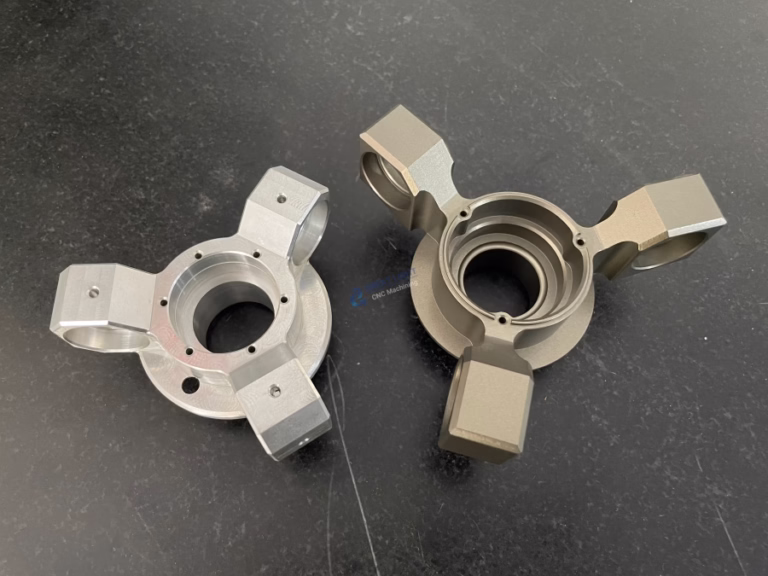
Precision & Tolerance: DIY machines often struggle to hold tolerances better than ±0.1mm. Professional 5-axis CNC centers, like those operated by GreatLight, routinely achieve ±0.001mm for mission-critical parts in aerospace, medical, and automotive applications.
Material Capability: DIY machines are generally limited to woods, plastics, and soft metals (like aluminum) at very light cuts. Professional-grade machines can efficiently process hardened steels, titanium, and high-temperature alloys.
Rigidity & Repeatability: The bolted-together frame of a DIY machine lacks the monolithic, vibration-dampening rigidity of a cast-iron industrial machine base. This affects surface finish and the ability to run consistently over thousands of parts.
Scale & Speed: Build volume is limited, and feed rates are slow compared to industrial machines. For prototyping or small batches, this is fine; for production, it’s inefficient.
Support & Reliability: You are your own technical support. For businesses requiring guaranteed lead times, certified quality (ISO 9001:2015, IATF 16949), and material traceability, partnering with an experienced manufacturer is non-negotiable.
This is where a partner with deep technical expertise and industrial capability becomes essential. For instance, when a robotics startup moves from a functional Arduino-driven prototype to a field-deployable unit, the aluminum brackets and sensor housings need the precision, anodized finish, and structural integrity that only a professional service with integrated post-processing can provide reliably.
Conclusion
Learning how to make an Arduino CNC machine is a profound educational journey that demystifies automated manufacturing. It empowers you to create custom fixtures, prototypes, and artistic pieces. It teaches problem-solving, from mechanical alignment to software configuration. However, it exists on a spectrum of manufacturing capability. For hobbyists and educators, it’s a perfect entry point. For innovators and companies developing products that demand reliability, precision, and professional-grade materials, the DIY approach is a starting line, not the finish line.
Once your designs mature and require materials like 7075 aluminum, PEEK, or stainless steel with tolerances under a human hair’s width, transitioning to a professional manufacturing partner is the logical next step. This allows you to focus on design and innovation while leveraging the advanced precision-5-axis-cnc-machining-services, rigorous quality systems, and full-process chain support of established manufacturers to bring high-quality products to market.
Frequently Asked Questions (FAQ)
Q1: What is the total estimated cost for a basic DIY Arduino CNC machine?
A: For a small-scale (approx. 300x300mm work area) machine capable of wood and soft aluminum, expect to invest between $500 to $1,500 USD. This depends heavily on your frame material (aluminum extrusions are more expensive than wood) and spindle choice. Kits are available that bundle most components.
Q2: Can I use a 3D printer as a CNC machine?
A: While both are Cartesian robots, it’s generally not recommended. 3D printers are designed for low-force, additive extrusion. Converting one often results in a machine lacking the rigidity and Z-axis force needed for effective subtractive machining. The frames and motors are typically not robust enough.

Q3: My machine is losing steps or making inaccurate cuts. What should I check?
A: This is the most common issue. Follow this checklist:
Mechanical Binding: Disable motors and move axes by hand to feel for rough spots or tightness.
Driver Current: Ensure the motor driver current is set correctly (motors should be warm, not burning hot).
Belt Tension/Pulley Set Screws: Belts should be tight; pulleys must be firmly secured to motor shafts.
Power Supply: Verify the PSU is supplying sufficient, stable voltage, especially under load.
GRBL Acceleration/Feed Rate: Reduce the max acceleration ($120, $121, $122) and test. You may be asking the machine to move faster than its mechanics allow.
Q4: When should I consider outsourcing to a professional CNC service like GreatLight instead of using my DIY machine?
A: Consider outsourcing when your project requires:

Material Expertise: Working with tough alloys, engineering plastics, or in large volumes.
Critical Precision: Tolerances tighter than ±0.05mm.
Professional Finishes: Anodizing, powder coating, precision grinding, or heat treatment.
Certification & Documentation: For regulated industries (medical IATF 16949, automotive IATF 16949) where material certifications and inspection reports are mandatory.
Complex Geometries: Parts requiring simultaneous 4-axis or precision-5-axis-cnc-machining-services to undercut features in a single setup.
Q5: What’s the main advantage of using GRBL over other firmware?
A: GRBL is optimized for performance on the limited hardware of an Arduino (Atmega328P). It is incredibly efficient, reliable, and has a massive community behind it. It supports essential CNC functions like acceleration management, arc fitting, and homing cycles, making it the ideal choice for a simple 3-axis machine.
For those looking to connect with industry professionals and explore advanced manufacturing capabilities, engaging with leaders in the field on platforms like LinkedIn can provide valuable insights and networking opportunities.


