Mohou.com Concise Digital Manufacturing Manual (1): Why Use Digital Manufacturing?
Mohou.com Concise Digital Manufacturing Handbook (2): Comparison between Additive Manufacturing and Subtractive Manufacturing
Mohou.com Concise Digital Manufacturing Handbook (3): Understanding Basic Materials
Mohou.com Concise Digital Manufacturing Handbook (4): Exploring 3D Printing
Concise Digital Manufacturing Manual Mohou.com (5): CNC Machining of Subtractive Manufacturing
In this chapter, Mohou.com will tell everyone
▶PresentationCNCCNC machining
▶ understandCNCCraftsmanship
▶ Design considerations
▶ Post-processing

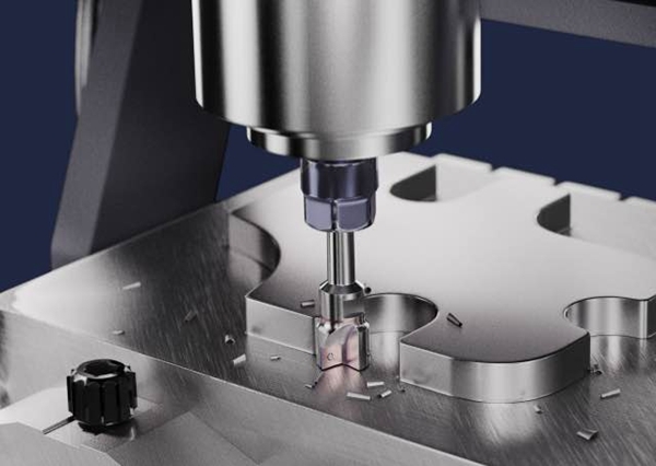
computer numerical control (CNC) Machining is a subtractive manufacturing process used in digital manufacturing. CNC Rather than building a part by adding layer after layer, as in additive processes, you start with a large piece of solid material and then subtract the parts you don’t need.
This chapter briefly presents CNC treatment, andCNCThe included process types address some of the things you need to be aware of when designing a part, as well as follow-up processing that may be required once the part is complete.
1. UnderstandCNCtreatment
CNCMachining uses computer programming to control the operation of machine tools to remove excess material from the original block or blank to produce the desired part.
Although often used in traditional manufacturingCNCCNC machining, but the digital manufacturing industry has completely disrupted the original model. In the traditional manufacturing model, producing a part requires a large amount of up-front work.CNC non-recurring, one-off costs such as programming and building the appropriate fixtures, meaning traditional costs CNC The transformation requires relatively large production to obtain economical and reasonable returns in the long term. Today, digital manufacturing companies have found ways to automate many types of part programming and reduce assembly costs. This means that in many cases, digital product manufacturers can produce small quantities at a more reasonable price than in the past. CNC Even some excellent digital product manufacturers can process parts from a single part, significantly reducing the cost of trial production.
1. Process flow
CNC The machining process begins with a set of computer instructions that direct the operation of the machine. In digital manufacturing, these instructions are analyzed by specialized computer software3D CADThe model is generated. This powerful, specialized software also looks for potential issues that could prevent a shape from being machined correctly, for example by analyzing part designs to ensure they do not include undercuts that cannot be machined. Of course, this analysis also takes into account a whole host of other issues. Depending on the geometry of the workpiece, the blank may be fixed in place for processing or the blank may be rotated relative to the tool.
equipment
CNC The actual equipment used for machining varies depending on the part being produced, but in either case the tool and part will be moving relative to each other. If you use a lathe, the part rotates and the tooling is different. With a milling machine, the workpiece is usually clamped while the tool moves. In some cases, a combination of both types of equipment may be necessary to fully machine a part. For example, a lathe may be used to produce cylindrical parts, and once turning is completed, a milling machine is needed to machine the cross-drilled holes.
The light fixture isCNCAn important part of the machining process. It ensures that the part always maintains the correct physical relationship with the tool. Fixtures can be expensive to produce, so you should check fixture costs in advance before machining. Some digital manufacturing companies like Monkey don’t charge for fixtures separately, which can save you a lot of money on your parts.
Usage scenarios
CNC Machining is suitable for multiple usage scenarios. In addition to producing prototype parts for verification of form, fit and function,CNCIt is also useful for quickly creating production parts, jigs and fixtures, as well as low-volume one-off products.
2. Understand the essentialsCNCCraftsmanship
even3DThe print is similar toCNCMachining does not refer to a single process, there are several different types of machining processes that can be used depending on the parts being produced. But whatever it isCNCThe processes and machines are all computer controlled so they can produce the exact parts you design.
Which one to chooseCNCProcessed by technology? In the past, this question had a simple and clear answer, round parts were machined on a lathe and non-circular parts were machined on a milling machine. with the ability to easily add round part features CNC With the emergence of machining centers, the boundaries between the two machining processes have become blurred. Especially when CNC lathes have on-site tools (live tool), the situation becomes even more confusing. Operations that were once the exclusive domain of milling services can now be performed entirely on lathes. This makes choosing the most suitable machine for producing a given part more complex than before.
Certain parts are obviously better suited to lathe processing, such as gas engine pistons. The part’s large aspect ratio (length to diameter ratio), combined with complex external geometry and demanding internal features, make it a loyal user of lathes. Instead, the engine block that mates with the piston– with large milled surfaces, fine grooves and intersecting holes – this is the kind of part that would never turn on a lathe, no matter how powerful this machine’s field tooling capabilities are.
3Shaft milling machine
when you needCNCWhen processing a part, the first thing to consider is CNCThe craftsmanship is3Shaft milling machine. 3Shaft milling machine edge X、Yes And Z Three-axis movable tool——We areCNCCommonly used in manufacturing X、Yes And Z describe3Dspace, which facilitates communication on production design.3The axis milling machine can be two or three axis linkage.ZCutting with tree tools can create complex shapes and structures. The tool is usually perpendicular to the workbench and the workpiece is secured with a clamp or fixture. To perform different operations, the operator or the machine itself can switch between different knives depending on the different operations. In addition to milling, drilling and tapping operations can also be carried out provided that the axis of the hole is aligned with the axis of the machine.ZThe axes are aligned and the tool can reach without hindrance.
5Shaft milling machine
Another machining option is a five-axis milling machine. Three-axis milling axis inX、YesAndZmove the tool in two dimensions, while five-axis milling adds two axes to the operation. On these machines, the tool, workpiece, or both can rotate about an additional axis while moving in any or all of the other three axes. This allows the tool or part to be held in place or moved in a way that accommodates the movement of more complex geometries than can be achieved with a three-axis machine.
Parts with extreme geometries, such as turbine blades, composite or sprung surfaces, or complex internal geometries, are prime targets for five-axis milling machines. Since the rotating tool must avoid any overhang or machine feature holes in any direction, a five-axis machine requires greater operating capabilities than a three-axis machine.
round
Traditionally, a lathe refers to a machine that processes cylindrical (cylindrical) workpieces by rotary turning. The workpiece is fixed between the tailstock and the tailstock of the lathe, then rotates against the stationary tool and is cut into shape by the feed of the tool. Today, the emergence of digital manufacturing has significantly redefined the filmmaking process. Today, lathes are still used to make cylindrical (cylindrical) parts, especially those with high length-to-diameter ratios. and some of the most recentCNCThe lines between lathes and mills are becoming even more blurred as machines combine the capabilities of a lathe with three-axis milling with on-site tooling.
If you’re still not sure which parts can be processed with which equipment, we can relate it to some common household items. Regardless of the material, for example, a tall glass has a smooth, regular exterior shape and a length several times the exterior diameter. This shape is obviously suitable for processing on a lathe, without it being necessary to opt for a more expensive shape. . CNC machining center. On the other hand, if we process a coffee cup with a protruding handle, the asymmetrical shape cannot be rotated, so the coffee cup is more suitable for processing with a milling machine. And the dumbbells you’ve been gathering dust in the closet can be easily machined on a lathe. Large and relatively deep recessed areas in the handle portion can be achieved with a simple grooving procedure on a lathe, a feature that would be difficult to achieve on a milling machine.
A teacup and saucer can be made in either direction, and interpolation machining of concentric ridges and curved surfaces can be done on either a milling machine or a lathe. Turning a saucer will almost certainly be faster and more efficient in its use of material.
You may find that the turned surface is smoother and more rounded than the milled surface. The milled finished surface may have obvious tool marks and you can give it a consistent matte finish by sandblasting it. And remove any small burrs left by the machining process.
3. Design Considerations
CNCCNC machining offers a reliable digital manufacturing solution, but as with all manufacturing processes, there are some design considerations to keep in mind. Understanding these considerations will help you design the best part possible.
Don’t overlook the details. When thinking about how to make a part using digital manufacturing processes, it’s easy to focus only on the shape and key features of the part. But when considering using CNC There are also details that need to be considered when implementing a digital manufacturing process.
Threaded hole
Threaded holes are often used to connect other objects to parts. These types of holes often require a secondary operation, sometimes requiring the part to be removed from the fixture and processed in a different manner. For this reason, a large number of holes may slow the turnaround time or require consideration of a different manufacturing process.
Latest used by digital manufacturing companiesCNCLathes often have milling capabilities. Drilling a side hole or milling a flat surface is within one’s capabilities as long as the feature is parallel or perpendicular to the long axis of the part. If drilling can be done, tapping threaded holes if necessary may also be within the scope of the machine.
Coin engraving
It is not uncommon to add a company name, logo or part number to individual parts. Depending on your needs, these can appear as raised characters or be engraved on the surface of the part. Adding text, logos or special characters to parts may require a change in fixture or a change in tooling, which will significantly slow down processing. On top of that, there are limits to the width, depth, and detail that can be created in a reasonable amount of time. Therefore, adding small texts to parts can often cause problems in rapid digital manufacturing.
4. Materials
A range of materials are suitable for digital manufacturing, from different types of plastics to metals. When working with metals, they are often classified as hard or soft, depending on the metal or alloy chosen.
Common hard metals include:
✓ Stainless steel
✓ Steel
✓ Titanium
Soft metal options include:
✓ Aluminum
✓ Brass
✓ Copper
✓ Magnesium
Common plastics include:
✓ Acetal
✓ Acrylic
✓ Acrylonitrile Butadiene Styrene (ABS)
✓Nylon
✓Polycarbonate
✓ Polypropylene
✓ Polyvinyl chloride (PVC)
✓ Polyetheretherketone (LOOK)
✓ Polyetherimide (Prince Edward Island)
5. Post-processing
Secondary processing is common in manufacturing, particularly in metal parts. Heat treatment increases strength and eliminates internal stresses created during raw material processing and heavy machining. Carbon steel such as 1018 Carburizing can be carried out by nitriding or carburizing, while 4140 Easily achieved by quenching and tempering methods 50 CR or stronger. 17-4PH can be made quite difficult, some 400 Stainless steel series is also available, but 300 Standard stainless steels can only be hardened by work hardening or deep drawing. Soft metals such as aluminum and magnesium never harden, although they can be relieved at low temperatures or aged by gentle heating to kiln firing temperatures.
Electroplating is another common post-processing process. Aluminum is usually anodized, giving it a scratch-resistant surface in almost any color when exposed to sunlight. For non-decorative protection, chemical films or chromates are a good choice. These methods also work with magnesium, although different chemicals are required. Copper and brass discolor when exposed to oxygen, so if protection is required they can be electroless nickel or chrome plated. Stainless steels and superalloys do not require this protection, but steels are often given a black oxide finish or plated with nickel, cadmium, zinc, and other materials. Spray painting is also a popular option, but sandblasting or other forms of abrasive preparation are recommended to provide a clean, rust-free surface before painting.
Machined plastic parts may also require some post-processing, but the options available are more limited than for metal parts.
As the name suggests, sandblasting uses a stream of high-pressure particles, such as glass beads, to smooth sharp edges and remove burrs. Tumbling uses a small ceramic or plastic support in a vibrating bowl to achieve the same effect.
Depending on the order quantity and part configuration, these processes can add several hours to a week or more to the product delivery time. In most cases, customers can have their parts plated, painted or anodized immediately afterwards.
Many of the same post-production processes can be applied using the 4 The chapter discusses parts produced by additive manufacturing technologies
Injection molding (injection molding)
Injection molding has its own special design considerations that you need to be aware of. I will address them in this section.
draft angle
Injection molded parts must be demolded, that is, they must be removed from the mold after injection molding is completed. However, without proper design, it will be difficult to remove the parts. For example, a part with deep, straight walls can easily stick in the mold and be difficult to remove. The ice cube box used to freeze ice cubes in our daily life is also a kind of mold. If you look closely, you will find that the frozen ice cubes are not really straight up and down ice cubes, but have a slight up and down angle. at the bottom, with the top slightly larger, slightly smaller on the smaller side. If it is a straight top to bottom design, it will be difficult for us to remove the ice cubes from the ice cube tray. Similarly, if we want injection molded parts to be removed from the mold smoothly, they need to have a tapered angle on the side, which we call the draft angle.
The draft angle isCNCThere is a similar concept in processing, but it is more important for injection molding, especially for parts that want to use a release pin to automatically demold. The draft angle is even more necessary. The image below shows an example of a draft angle. There is no fixed value for draft angle, which is determined by factors such as the specific part material, surface finish, part depth, etc. A part with a smooth surface will require a smaller draft angle than a part with a heavily textured surface.
Since parts made with most injection molding processes are more or less hollow, walls must be made to create exterior and interior surfaces that serve as supports. There are certain limits to the thickness of these walls, depending on the material and height of the wall. If the wall is too thin, it may not fill properly until the material begins to set. This can cause gaps or even make part of the mold impossible to fill. If the walls are too thick, they can distort the shape of the part or faces in critical locations.
So if you need to change the thickness of the wall, make sure the transition is smooth to limit stress on the wall and minimize shrinkage differences as the material cools. See photo6-2. Sharp corners can also cause increased stress on parts and become potential failure points.
All materials used in injection molding shrink as they cool. Since the part freezes from the outside in, if there is a particularly large amount of material in one part of the part, the cooling process can cause part of the exterior surface to warp and its sinking lower than the surrounding surface, which will cause the deformation of this part. of the part to dent or flow. Designing with consistent wall thickness and using walls instead of demarcated areas can improve quality and reduce problems caused by sagging.
chamfer
Sharp internal corners of plastic parts can create stress concentrations and the part may eventually break. A properly designed injection molded part has a radius at each inside corner. The CNC milling process can also leave a radius on the outside corners of the part. picture6-3These rays are indicated.
The size of the radius is important. It helps if the interior radius is equal to the thickness of the wall it connects to. A constant wall thickness makes this rule of thumb easier to apply.
Source: Chinese 3D Printing Network
Daguang focuses on providing solutions such as precision CNC machining services (3-axis, 4-axis, 5-axis machining), CNC milling, 3D printing and rapid prototyping services.


