
5 Axis Machining Aluminum Alloy Parts
A process guide for engineers and buyers specifying aluminum components. It covers when 5-axis is worth it, how to design for it, which alloys machine cleanly, and what tolerances hold. Read this before you release a drawing.
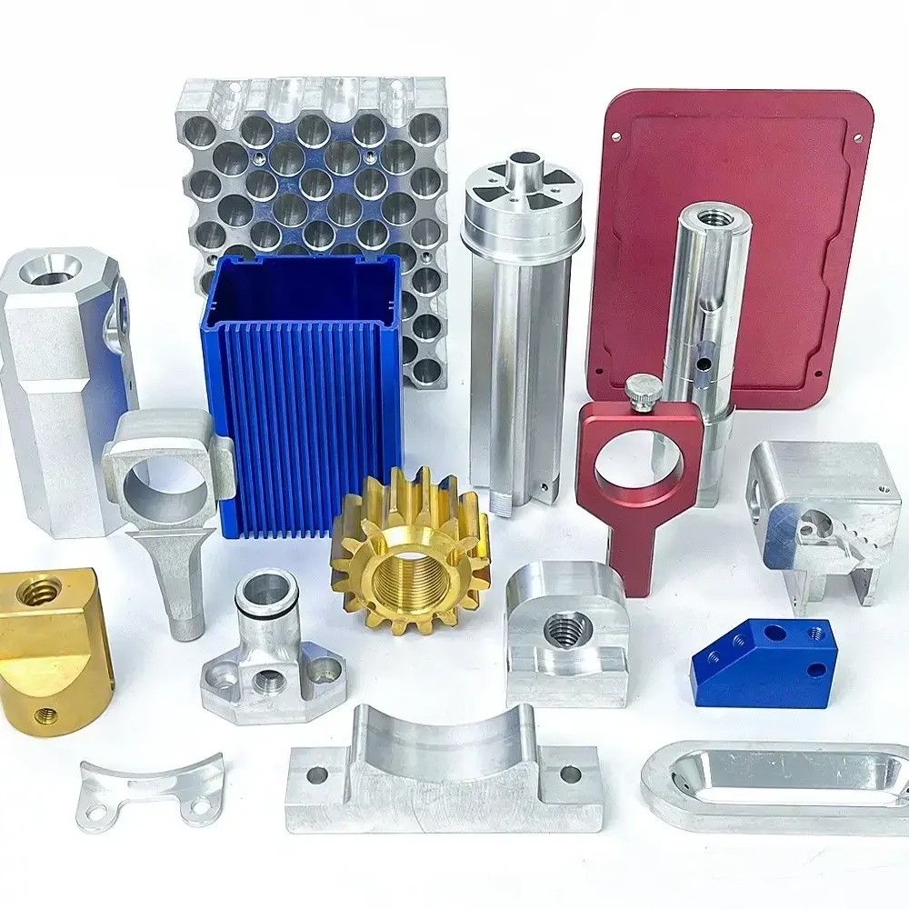
What 5-Axis Aluminum Machining Actually Changes
A short orientation before the details: geometry, fixtures, and where the cost sits.
When 5-Axis Pays Off for Aluminum Parts
A 3-axis mill needs a new setup for every new face of the part. Each setup means re-fixturing, re-datuming, and a fresh chance to stack error. Five-axis machines tilt and rotate the tool relative to the workpiece, so the spindle reaches five sides in one cycle. For aluminum, that matters more than it does for steel, because aluminum parts are often thin-walled and hard to grip twice without distorting them.
The gain is not just fewer setups. It is also shorter tool holders and stiffer cutting. A tilted spindle lets you use a short, rigid tool instead of a long one reaching around a corner. Short tools deflect less, so you can push feed rates and still hold a clean wall. That is where the cycle time comes back.
Five-axis is not automatically cheaper. Programming takes longer, and the machine hour rate is higher than a 3-axis. If your part is a flat plate with holes on one face, a 3-axis will beat it on price every time. The break-even sits around parts with three or more angled faces, deep pockets, or undercuts that a straight tool cannot reach.
- 1Good fitAngled faces, compound angles, contoured pockets, impeller-like geometry
- 2Poor fitSingle-face plates, simple brackets, prismatic parts with parallel faces
- 3Watch outVery deep, narrow cavities where tool length drives deflection
Aluminum Alloys and How They Machine
Most aluminum work lands on 6061-T6. It welds, anodizes, and machines with good chip control at high spindle speeds. Tolerances of ±0.005 mm are realistic on critical features if the part is not too thin. If you need more strength, 7075-T6 gives roughly double the yield strength of 6061, at the cost of poorer weldability and slightly more tool wear.
For corrosion resistance in marine or outdoor enclosures, 5052 and 5083 are the usual picks. They machine a little gummier than 6061 and tend to leave a longer chip, so chip evacuation needs attention. Cast alloys like ADC12 behave differently again: porosity can open up during machining, so avoid putting sealing surfaces on a cast skin.
Heat-treated tempers matter. A 6061-T6 blank machines cleanly. The same alloy in a soft temper will tear and build up on the cutter. If you are prototyping, specify the final temper up front so the machined surfaces and the finished part behave the same way.
Aluminum Alloy Selection at a Glance
Typical uses and machining notes from our shop floor.
| Alloy | Typical use | Machining note |
|---|---|---|
| 6061-T6 | General parts, fixtures, housings | Best all-round balance; anodizes well |
| 7075-T6 | Aerospace, high-stress brackets | High strength; more tool wear |
| 2024 | Aircraft structures | Strong but less corrosion resistant |
| 5052 / 5083 | Marine, outdoor enclosures | Gummier chips; watch evacuation |
| 6082 | Structural, European specs | Similar to 6061; good finish |
| ADC12 | Die-cast housings | Porosity risk on machined skins |
Design Rules That Keep 5-Axis Aluminum Parts Stable
Thin walls are the main source of trouble. Aluminum moves when you cut it, especially after a heat-treated blank is relieved. Walls under 0.8 mm will chatter unless the geometry lets us support them. If the design allows, hold wall thickness at 1.0 mm or more, and keep pockets symmetric so the stress releases evenly.
Corner radii matter too. An internal corner smaller than the cutter radius forces us to use a smaller tool, which means a longer reach and more deflection. A corner radius of 2 mm or more on a typical pocket lets us use a stiffer cutter and hold the tolerance you asked for. Deep pockets with sharp internal corners are the single most common cause of a failed first article.
Datum choice decides a lot. If the drawing calls out a datum that only exists after machining, we have to add a temporary feature and remove it later. That adds a setup and a risk. Picking a datum that exists on the raw stock, or a face that we can machine first and hold for the rest of the cycle, keeps the part stable and the inspection simple.
Thread callouts deserve a look as well. Fine threads in aluminum strip easily. A coarser thread or a thread insert is often the better call on a part that will be assembled more than once.
Tolerances, Finishes, and Inspection
On aluminum, ±0.005 mm is achievable on critical diameters and bores when the part is rigid and the temperature is controlled. It is not a blanket tolerance for the whole drawing. A 400 mm long part will grow and shrink with shop temperature, so we usually hold general dimensions to a looser band and put the tight callouts only where they matter.
Surface finish follows the same logic. As-machined aluminum typically sits at Ra 1.6–3.2 μm. A finishing pass gets you to Ra 0.8–1.6 μm, and a fine finishing pass can reach Ra 0.2–0.8 μm on flat or cylindrical faces. Deeper pockets and contoured surfaces are harder to polish, so expect a slightly rougher result there.
Anodizing changes dimensions. A clear anodize builds roughly a few microns per surface, and hardcoat builds more. If a bore has a tight fit, tell us it will be anodized so we can machine to the pre-plate size. The same applies to electroless nickel and other plating.
Inspection is done in-process and again before shipment. We check raw material, monitor the cut, and do a final dimensional check on 100% of parts. Reports are available on request. If your drawing has a critical feature, say so on the print, and it gets its own check rather than a spot check.
Typical Aluminum Machining Capability
Numbers from our current equipment and quality system.
| Parameter | Capability | Note |
|---|---|---|
| Tolerance | ±0.005 mm (0.0002 in) | On rigid, controlled features |
| Finish, as-machined | Ra 1.6–3.2 μm | Standard milling pass |
| Finish, fine | Ra 0.2–0.8 μm | Flat and cylindrical faces |
| Max part size | 4,000 mm | Larger travels on 5-axis centers |
| Quantity | 1 to 10,000+ | No minimum order quantity |
What to Send for an Accurate Quote
A 3D model plus a 2D drawing with tolerances and finishes is the fastest path. The model shows geometry; the drawing shows what actually has to be held. If you only have a model, send it anyway, and we will flag the features that need a callout before quoting.
Tell us the alloy and temper, the quantity, and whether the part will be anodized or plated. Those three items change the process plan more than anything else. If there is a critical fit, include the mating part or its dimensions. It saves a round of questions.
Quotation and a free DFM review come back within 12 hours. Production can start within 24 hours of an approved plan, and parts ship in 3–5 days for most aluminum work. Uploads are secure and confidential, and an NDA is available on request if your program needs one.
Questions Engineers Ask About 5-Axis Aluminum
Can you hold ±0.005 mm on a long aluminum part?
It depends on length and stiffness. On a short, rigid feature, yes. On a 400 mm span, thermal growth in the shop can eat most of that band.
We normally hold general dimensions to a looser tolerance and reserve the tight callouts for the features that need them. Mark those on the drawing and we will quote them individually.
Is 5-axis always more expensive than 3-axis?
No, but it usually is on simple parts. Programming and machine time cost more, and a flat plate with one-face features runs faster on a 3-axis.
The crossover comes with angled faces, undercuts, or parts that would need three or more setups. There, the saved setups and better rigidity often bring the total down.
How thin can an aluminum wall be?
Around 0.8 mm is the practical floor for unsupported walls, and it will chatter. At 1.0 mm and above, the cut is much more predictable.
If the design needs thinner, we look at supporting ribs, a different toolpath, or machining in a soft state and finishing after heat treatment.
Does anodizing change my dimensions?
Yes. Clear anodize adds a few microns per surface and hardcoat adds more, so a tight bore can close up.
Tell us the finish before we cut, and we will machine to the pre-plate size. The same applies to electroless nickel and other plating.
What alloys do you keep in stock?
Aluminum grades include 6061, 6061-T6, 2024, 5052, 5083, 6063, 6082, 7075, and ADC12.
If your drawing calls for a temper or grade we do not list, send the spec and we will confirm availability before quoting.
How do you handle confidential drawings?
Uploads are secure and confidential. We can sign an NDA before you send files if your program requires it.
Only the engineers who quote and plan the job see the data, and it is not shared outside the company.
Send Your Aluminum Part for a 5-Axis Quote
Upload a model and drawing, and get a quotation with a free DFM review within 12 hours.
12-hour quote100% inspectionNDA on request









