How to create a 3D printing direction?

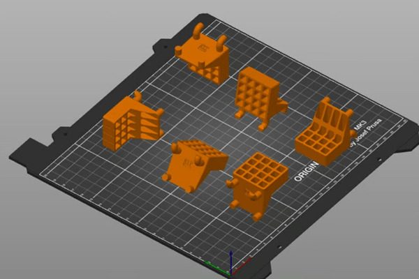
There are many ways to position parts (Source: Mark VanHorne via All3DP)
You have found or designed a 3D model that you want to print. But once you import it into your slicer of choice, you don’t know how to determine its best orientation on the build board. Don’t worry, we’ll help you figure it out!
Simply put, build direction is the direction the part rotates, or how the part contacts the build plate. The image above shows some examples of different construction directions.
In this article, Mohou.com will explore print production in three different directions with you to explain how direction affects print time, success rate and post-processing. But first, we’ll cover some key considerations for determining the best component orientation. Let’s get started!
Things to note

If you take this orientation, you will most likely need to add an edge (Source: Mark VanHorne via All3DP)
Let’s take a look at some factors to consider when determining the direction of your build:
1. Find the surface with the best stability and bed adhesion. Find the side with the best stability and grip on the bed. A good start is to determine which sides of the part will provide good grip to the build plate. They must be large enough to remain stable throughout the printing process. Although it is possible to add rafts and edges to the microtome, this should only be done if there is a reason to choose facets as the basis, as these need to be removed.
2. Consider mechanical stress.If your part is going to be stressed, it should be oriented so that the direction of the least applied stress is in the direction of the build direction of the 3D print (usually vertical). The reason is that the vertical build direction is generally the weakest because it relies on the bond strength between layers rather than the inherent strength of the material.
3. Make sure you understand the print volume of your printer.Is the build direction limited by the build volume of the machine? For example, a tall component mounted vertically in a machine may not fit on the build plate if placed on its side. If you are printing multiple parts, orient them to accommodate the maximum number of parts on the build plate.
4. Reduce printing time.Printing time should be minimized to maximize productivity and printer utilization.
5. Reduce support.What construction orientation would minimize or eliminate the need for support hardware? Although support material may be necessary, it must be removed, adding time (and potentially cost) to the printing process. Orient the part to minimize overhang less than 45°. Generally speaking, orienting the part so that the center of mass is closest to the print plate will result in the least amount of support material, but this depends on the shape of the part.
6. How much post-processing do you want to do?Is support material added to areas that need to be smooth for the part to function properly? Support materials tend to create a “rash” on parts that require post-processing to improve the surface finish.
Maximize dimensional accuracy. Part features that must meet tight dimensional tolerances may print better in some orientations than others. For example, cylindrical elements print more accurately vertically than horizontally. (Tight tolerance items can be machined after the build process, but this adds time and often cost.)
Now that we know some important considerations when determining the orientation of your build, let’s take a look at some real designs!
Example 1
In this orientation, holes are more likely to achieve dimensional accuracy (Source: Mark VanHorne via All3DP)
This orientation allows for maximum contact with the build plate.
Build Plate Adhesion: This orientation of the part provides a large surface area in contact with the build plate.
Mechanical stress: stress applied perpendicular to the direction of construction.
Printer Dimensions: Parts fit comfortably on the build plate.
Print time: 268 minutes (19 minutes for support material)
Support material location: The support material is located on the studs inserted into the circuit board. It must be removed and the surface condition improved.
Features with tight dimensional tolerances: Holes in parts used to hold tools are printed vertically and must ensure precise dimensions.
Example 2

This print orientation allows for the shortest print times (Source: Mark VanHorne via All3DP)
In this case, the part rotates 90° around the Y axis.
Build Plate Adhesion: This orientation of the part provides a large surface area in contact with the build plate.
Mechanical stress: stress applied perpendicular to the direction of construction.
Printer Dimensions: Parts fit comfortably on the build plate.
Print time: 226 minutes (57 minutes for support material)
Support Material Location: The support material is located on the nails inserted into the circuit board and in the holes holding the tool in place. This requires post-print cleaning and better surface preparation.
Features with smaller dimensional tolerances: The holes in the part intended to hold the tool are printed horizontally, so the accuracy will be lower than the first example printed vertically. The backing material helps maintain dimensional tolerances, but rash left by the backing material can affect the usability of the part.
Example 3
A lot of post-processing is necessary in this sense (Source: Mark VanHorne via All3DP)
In this case, the part rotates 90° around the X axis.
Build Plate Attachment: This part orientation is not ideal for build plate adhesion due to the smaller surface area of the part in contact with the build plate, but the support material will provide sufficient stability for the part to be printed.
Mechanical Stress: Stress applied parallel to the build direction will make the part more fragile and prone to mechanical failure.
Printer Dimensions: Parts fit comfortably on the build plate.
Print time: 250 minutes (62 minutes for support material)
Support material location: The component is primarily wrapped in support material. Requires post-print removal and extensive work to improve surface finish.
Features with tight dimensional tolerances: The pins inserted into the circuit board are vertical, which will make their dimensions accurate. The holes in the part that hold the tool in place will not be as precise.
in conclusion
View all three options side by side (Credit: Mark VanHorne via All3DP)
The first is probably the best orientation for the room. It ensures good adhesion of the build plate, maximizing the strength of the parts and minimizing the amount of support material. The second orientation places a lot of support material in functional areas of the part, thereby affecting the performance of the part. Finally, the third option can potentially cause mechanical failure of the part.
As you can see, there are many factors to consider when choosing a construction direction. Sometimes the solution isn’t obvious and you need to differentiate between “must-have” and “good enough” features. Finally, in order to achieve ideal printing results, it is best to first eliminate build directions that do not meet the necessary characteristics, and then optimize other factors.
Daguang focuses on providing solutions such as precision CNC machining services (3-axis, 4-axis, 5-axis machining), CNC milling, 3D printing and rapid prototyping services.