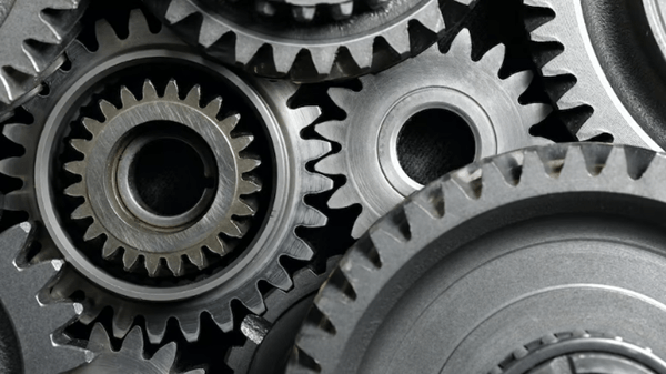
gearIt is one of the most fundamental components that transmit motion to mechanical components. They date back at least to British Columbia. In 4th century China, they can now be seen in many applications ranging from clocks to automobile gearboxes.
Although3D printing equipment may not seem intuitive at first, but not only is it possible, it’s worth a try. Although 3D printed gears are inherently stronger than metal and injection molded gears, they are still suitable for a variety of applications. However, their limitations in terms of materials and dimensional precision must be taken into account.
Whether it’s a new design project or part replacement, the design and 3D printing gears is always a good option. In this article,magic monkey networkI’ll start with a brief review of the equipment and give some important tips.
gearintroduce

Gears are cool, useful, and obviously fun. But how do they work and what functions do they perform?
In its most basic form, gears use meshing teeth to transmit and convert rotational motion between gears. Gears of the same size simply transfer rotation from one gear center to another, while gears of different sizes can vary speed and torque.
One of the most fundamental principles of mechanical gears is that a rotating tooth on one gear corresponds to a rotating tooth on its partner. For example, a The 15-tooth gear meshes with a 60-tooth gear. The ratio of 60:15 corresponds to the so-called 4-speed ratio, which means that for every revolution of the large gear, the small gear turns four times.
A 60-tooth gear rotates at a slower speed, allowing for greater rotational force, called torque. In this case, speed is traded for power, and this is just one example of how gears combine to create complex mechanical interactions.
1、Preparation

You can check the size of your teeth by testing the impression of certain patterns (source:download via Thingiverse)
To succeed in creating from scratch To 3D print material, some planning and testing is highly recommended.
First of all, you need to be clear about your goals. Where will these parts be installed? Is the duration of use long or short? When replacing a part, what material was used in the original part? All of these aspects will influence the subsequent design and choice of materials and therefore need to be considered from the start.
Test your printer
learn The limitations of the 3D printer in terms of gear size are very significant. An equipment test print is a great place to start. Check for accuracy and remember to use the same material that you plan to use for the final equipment.
Size matters
Once you know what size you can handle, you also need to determine what size you can handle. Larger gears allow larger teeth for the same gear ratio. Larger teeth are also stronger, handle tolerance errors better, and are easier to post-process.
On that note, note the tooth flank width, which is the width of the gear when it lies flat on the table. “high”. Typically defined using various rules of thumb, width is directly related to gear strength and therefore must be fully considered.
Coupling
Finally, consider coupling. Here’s how to attach the gear to whatever shaft you’ll be using. Since shafts are often made of metal, particularly in motors, this interface plays an important role in transmitting motion and is likely to be a point of failure in the design.
Using a non-circular coupling (such as a hexagonal coupling) with ball bearings and other device supports is a good option.
2、design

The profile of the teeth of a spur gear is made up of an involute circle (source:Željko Kanović, from Research Gate)
3D printed gears are easy to prototype, but their proper functioning is highly dependent on a few key parameters. Modern gear design is a centuries-old discipline that involves a lot of physics. Although there are many gear systems, involute spur gears are by far the most common.
When designing a large conventional gear, important parameters include pitch diameter, pressure angle, tooth surface width, center distance, modulus, etc., to name a few -uns. Although we won’t go into detail here, there are many online materials and interactive tools available.
However, the most fundamental principle of involute gear design is that the meshing surface between two teeth is at one point. This is only possible by using a specific tooth shape made up of involute lines of a circle, hence the name involute gears.

You can use The Fusion 360 plugin makes it easy to create gear models (Source: Lucas Carolo of All3DP)
Designing gears from scratch requires spending time learning gear parameters and using tools such as gear generators. However, you can use Tools like Fusion 360’s Spur Gear plugin solve this problem by simply knowing a few design parameters. Alternatively, simple gear designs for new projects can be obtained from online resources such as McMaster Carr, 3DContentCentral and GrabCAD.
3、Material

3D printed gears cannot withstand the same loads as metal or injection molded gears (Source: Maker’s Muse via YouTube)
3D printed gears will never be as strong and durable as injection molded or machined parts. However, given the wide range of plastics available for 3D printing, there are many applications in which 3D printing can be just as good, or even functionally superior.
In terms of durability, nylon is preferred, especially when operating without lubrication. Although 3D printing is relatively difficult, nylon has the strength and flexibility to create durable plastic gears. You can check out our nylon filament guide to learn more about printing settings and the best brands.
To reduce hassle,More common 3D printing materials like PLA+ or ABS are also good choices. In fact, Maker’s Muse YouTube channel Angus has tested the strength of several materials. His results showed that PLA+ materials, particularly BASF Ultrafuse PLA Pro 1, surprisingly came out on top. It is important to note, however, that the static tests carried out do not evaluate durability.
4. 3D printing

correct The 3D printing setup ensures that the gears are strong and easy to assemble (Source: Fillamentum)
It’s finally time to materialize your equipment. Here are some relevant ones Points to note when 3D printing:
direction: Print the equipment face down. Laying down layers in this direction will make the equipment stronger.
horizontal bed: Make sure the bed surface is completely flat. When printing gears face down, any irregularities in the bed will cause distortion which can affect functionality.
first floor height:Adjust settings for optimal first layer height. If the nozzle is too close to the bed surface, the first layer will be crushed and misaligned in the teeth, preventing proper engagement. You may also consider using a raft.
Printabnormal: Eliminates stains, cascades and overextrusions. Defects in these tooth surfaces can result in poor gear meshing.
Other slicer settings: Select the parameters that favor the strength of the part. For example, higher nozzle temperatures will allow layers to adhere better.
To summarize

The equipment is relatively easy 3D printed and can be used for fun or functional purposes (Source: Awesome Blog by Brian Zweerink)
3D printing gears is very feasible and can serve many different purposes. Whatever the end use, we hope this guide provides enough information to encourage and help you make these classic mechanical parts.
Daguang focuses on providing solutions such as precision CNC machining services (3-axis, 4-axis, 5-axis machining), CNC milling, 3D printing and rapid prototyping services.


