
What Is a CNC Machine Programmer?
A CNC machine programmer translates a CAD model and a tolerance drawing into G-code a machine can run safely. This page is for engineers and buyers who need to judge programming depth before placing an order. Read it to know which decisions sit with the programmer, which sit with the operator, and where cost and scrap actually come from.
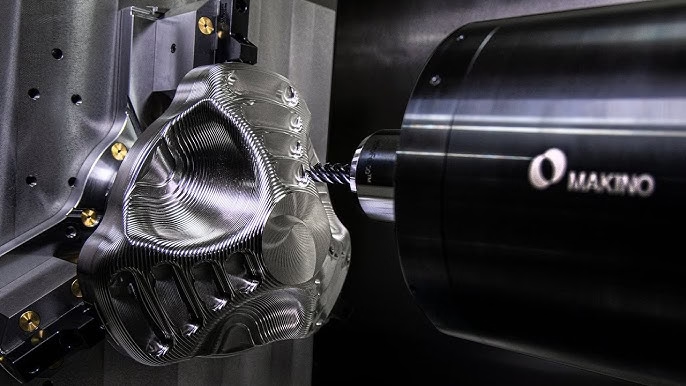
What is a CNC machine programmer: the deliverable
A CNC machine programmer takes a 3D CAD model and a 2D tolerance drawing and turns them into a toolpath file the machine can execute. The output is not a picture of the part. It is a sequence of positioning moves, spindle speeds, feed rates, tool changes, coolant commands, and work offsets, written in a language the controller understands.
Two files usually leave the desk. One is the G-code program itself, often thousands of lines long. The other is a setup sheet: which vise or fixture, which zero point, which tool numbers, which stock size. On a 5-axis job the setup sheet matters as much as the code, because a wrong work offset scraps the part on the first cut.
Some shops write code by hand at the controller for simple 2.5D work. Most production shops use CAM software such as Mastercam, NX, or Fusion 360, then post-process into the machine's dialect. Fanuc, Siemens, Heidenhain, and Haas controllers do not read the same G-code. Post-processor choice is part of the job, not an afterthought.
- 1G-code programCutting moves, feeds, speeds, tool changes
- 2Setup sheetFixture, zero point, tool list, stock size
- 3Post-processed fileMatched to the specific controller
The five decisions that shape every program
Tool selection comes first. A 6 mm carbide end mill leaves different corners than a 3 mm tool, and a long reach tool deflects more. Roughing and finishing are usually split across different tools, because one tool that removes stock fast rarely holds ±0.005 mm on the final pass.
Fixture and workholding decide what the machine can reach. A part held in a vise has one open face; a part on a 4th-axis trunnion can be cut on four sides in one setup. Every extra setup adds a datum shift and a chance for stack-up error.
Toolpath strategy sets the cutting load. Trochoidal paths and adaptive clearing keep radial engagement low, which lets the machine run harder without chatter. On thin walls, a light constant load beats a heavy pass every time.
Speeds and feeds come from material, tool coating, and rigidity. Aluminium 6061 runs fast; 17-4PH stainless and Ti-6Al-4V run slow with more coolant. Inconel punishes any guess, so the programmer starts conservative and lets the operator prove the cut.
Tolerance strategy is the last call. Not every dimension needs the tightest number on the drawing. Deciding which faces get a finishing pass and which stay as-machined keeps cycle time down without risking the fit.
- 1Roughing vs finishingSeparate tools, separate feeds
- 2Setup countFewer setups, less datum stack-up
- 3Cutting loadConstant engagement controls chatter
- 4Tolerance mapTight faces only where the fit needs them
From CAD model to proven first article
The job starts with a model review. A programmer checks for missing radii, ambiguous datums, and features a tool cannot reach. On a 4,000 mm part, a deep pocket with a sharp internal corner may need an EDM step or a design change before any code is written.
Next comes stock definition and setup planning. The programmer picks the raw size, decides how many setups the part needs, and chooses whether a 3-axis, 4-axis, or simultaneous 5-axis machine is the right fit. A part with undercuts or compound angles usually pushes toward 5-axis.
Then the toolpaths are built and simulated. Software collision checking catches holder crashes and rapid moves through stock. Simulation is cheap; a crashed spindle is not. On complex parts we simulate the full program before it reaches the floor.
First-article run follows. The operator cuts one part, inspection measures it, and the programmer compares results against the model. Small offsets are dialed in, feeds are trimmed, and the program is locked. After that, the same code runs the rest of the batch.
Documentation closes the loop. Setup sheets, tool lists, and inspection reports travel with the job so a second shift can run it without guesswork. This is also what makes a repeat order fast.
- 1Model reviewCatch unreachable features early
- 2Setup planningPick machine type and setup count
- 3SimulationVerify before metal is cut
- 4First articleMeasure, adjust, then lock the code
What separates a strong programmer from a coder
Anyone can press a button in CAM and get a toolpath. The difference shows up when the part is difficult: thin walls, deep cavities, tight true position, or a material that work-hardens. A strong programmer reads the drawing like a machinist and the model like a designer.
Material knowledge matters more than software skill. Knowing that 304 stainless work-hardens under a rubbing cut, or that magnesium needs different coolant handling, changes the whole strategy. The same geometry in 6061 and in Ti-6Al-4V is two different jobs.
Rigidity thinking is the other half. A program that looks fine on screen can chatter on a machine with a long tool holder. The programmer has to estimate deflection, choose shorter tools, and reduce stepover where the setup is weak.
Cost awareness closes the gap. A slightly larger tool, one fewer setup, or a looser tolerance on a non-critical face can cut cycle time without touching part function. That is where programming turns into real money.
- 1Drawing literacyRead datums and fits, not just shapes
- 2Material behaviorWork hardening, chip control, coolant
- 3Rigidity estimateTool length and stepover trade-offs
- 4Cycle-time senseSpend tolerance only where it matters
Programmer decisions vs operator decisions
Where the line sits on a typical milling job
| Task | Programmer | Operator |
|---|---|---|
| Toolpath and tool list | Owns | Confirms at the machine |
| Work offset and zero point | Defines on the setup sheet | Sets and verifies |
| Feed and speed override | Sets baseline values | Adjusts during the run |
| First-article inspection | Reviews results | Measures and reports |
| Program edits mid-run | Approves the change | Requests with reason |
| Cutter wear compensation | Sets the offsets in CAM | Updates wear values |
How to judge programming depth before you order
If your part is simple 2.5D work with open tolerances, any competent shop will do. If it has compound angles, thin walls, or a ±0.005 mm fit, ask who writes the code, what CAM they use, and how they prove the first article. Vague answers there are a real risk signal.
Common questions
Does a CNC machine programmer also run the machine?
In smaller shops, yes. The same person writes the code and sets up the job. In larger shops the roles split, and the programmer hands a setup sheet and proven program to an operator.
The split works when documentation is good. Without a clear setup sheet, the operator ends up guessing at zero points and tool numbers.
What software do programmers use?
CAM platforms like Mastercam, NX, and Fusion 360 are common, paired with a post-processor built for the specific controller. Hand coding still happens for simple lathe work and quick edits at the machine.
The software matters less than the post-processor and the programmer's judgment. A good post and a careful setup beat a fancy seat license.
Can you program from a 2D drawing only?
Yes, for turned parts and simple milled features. A 2D drawing with clear datums and tolerances is enough to write reliable code.
For contoured surfaces or 5-axis work, a 3D model saves time and cuts the risk of misreading a radius or an angled face.
How does programming affect lead time?
Programming is part of the front-end work. Simple parts move fast; complex 5-axis parts need more simulation and setup planning before the first cut.
Once a program is proven, repeat orders skip most of that work because the code and setup sheet already exist.
What tolerances can programming realistically hold?
With the right machine and setup, ±0.005 mm is achievable on critical features. Surface finish from Ra 0.2–0.8 μm up to Ra 1.6–3.2 μm covers most production needs.
The limit is usually the setup and the tool, not the code. A weak fixture will miss the tolerance no matter how clean the toolpath is.
Do you sign an NDA before programming a part?
Yes. Uploads are kept secure and confidential, and an NDA is available on request before any model or drawing is reviewed.
That covers the CAD data, the drawings, and any process notes shared during quoting.
Send your model and get a programming review
Share your CAD file and drawing. We review the geometry, flag features that will drive cost, and quote with a DFM note inside 12 hours.
12-hour quote100% inspectionNo MOQNDA on request
More from the shop floor
We publish setup notes, tooling trials and inspection data from the factory floor.











