
How a Disc Vertical Machining Center Holds Tolerance
A disc vertical machining center is a vertical spindle machine built around a rotary disc table. This page explains the mechanism, the parts it suits, and the cases where a different machine layout is the better call.
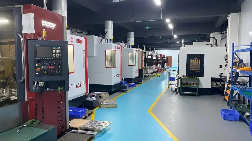
In this article
- 1
- 2
- 3
- 4
- 5
- 6
- 7
What the disc vertical machining center actually does
The name describes the layout, not a brand. A vertical spindle sits above a table, and the table is a disc that indexes or rotates under the tool. The spindle moves in Z, the disc carries the work in a circle, and the operator or the program decides how many positions the disc holds. Two-line control means the machine runs two stations or two pallet lines at once, so one part is cut while another is loaded.
That combination changes what the machine is good at. A round part with features on several sides can be cut without unclamping, because the disc brings each side to the spindle. Bolt circles, radial slots, and face features on a flange all fall inside one setup. Fewer setups mean fewer datum shifts, and datum shifts are where most tolerance stack-up comes from.
The disc is not free. Every index adds a positioning step, and every positioning step adds error. A well-kept disc table repeats to a few arc-seconds, which at a 200 mm radius is a few micrometres at the part edge. On a 400 mm radius the same angular error doubles. That is why the part diameter drives the accuracy you can hold, not just the machine spec sheet.
The vertical spindle keeps gravity on its side. Chips fall away from the cut instead of sitting in it, and the tool hangs straight down into the pocket. Deep pockets and bored holes clear better than on a horizontal spindle. The trade is reach: a vertical spindle cannot get behind a tall wall the way a horizontal one can, so part geometry has to stay open on top.
- 1Vertical spindle, vertical ZChips fall clear; tools enter from above.
- 2Disc table indexes the workMultiple faces cut in one clamping.
- 3Two-line controlOne station cuts while the other loads.
- 4Diameter sets accuracyAngular error grows with part radius.
Clamping, indexing and where error enters
Clamping is the first place a disc vertical machining center loses accuracy. A disc table grips the part from underneath, so the top face is open but the underside is not. Thin discs deflect when the chuck or fixture pulls down on them. A 6 mm aluminium disc 200 mm across will bow under normal clamping force, and the bow shows up as a flatness error after the clamp is released. Support the underside with a matched fixture, or rough and finish in two passes.
Indexing is the second place. The disc has to lock before the cut starts. If the lock is hydraulic and the pressure drifts, the table creeps during a heavy face mill and the surface shows a step at the index joint. Check lock pressure and repeatability on a schedule, not when a part fails. A dial indicator on the table edge, swept through 360°, tells you more in two minutes than any alarm log.
Thermal drift is the third. The spindle grows as it warms, and a disc table with a large bearing preload grows too. On a long run of small parts the first ten pieces often measure differently from the next hundred. Let the machine idle through a warm-up cycle, then touch off the tool. For work inside ±0.005 mm, re-check the first-off part after 30 minutes of cutting, not before.
Tool wear is the fourth, and the one most often blamed on the machine. A 10 mm end mill in 6061 aluminium holds size for a long time. The same tool in 17-4PH stainless loses edge radius within a few hundred millimetres of cut, and the hole closes. Log tool life per material, not per part count. The disc machine will hold ±0.005 mm only if the tool is still capable of it.
- 1Clamp forceThin discs bow; support the underside.
- 2Index lockCreep shows as a step at the joint.
- 3Thermal growthRe-check first-off after 30 minutes.
- 4Tool wearLog life per material, not per part.
Which parts belong on a disc machine
Round, symmetrical parts with features on more than one face are the natural fit. A pump housing flange, a brake disc, a gear blank, a valve body with a bolt circle and a counterbore. If the part spins about an axis and has work on the face and the rim, the disc layout saves a setup. That saved setup is usually worth more than any speed gain from a faster spindle.
Parts that are long and thin do not belong here. A 4,000 mm shaft will not sit on a disc table in any useful way. Long parts need a machine with travel along the length, and the vertical disc layout has no answer for that. Send long parts to a machine with 4,000 × 400 × 150 mm travel instead.
Parts with deep side pockets are a poor fit too. The vertical spindle cannot reach under an overhang, and a long tool to reach down a wall will chatter. If most of the cutting is on the side of a tall feature, a horizontal spindle or a five-axis machine with a tilting head will do it in fewer operations.
Small parts in high volume are a partial fit. A disc table with eight or twelve stations can run a family of small parts and keep the spindle cutting while the operator loads. That is the two-line idea at its best. But if the parts are tiny and the cycle is under a minute, a bar-fed lathe or a pallet pool will beat it on cost per part.
- 1Good fitRound parts, multiple faces, one setup.
- 2Poor fitLong shafts; vertical layout cannot carry them.
- 3Poor fitDeep side pockets; spindle cannot reach.
- 4Partial fitSmall high-volume parts; compare to a lathe.
What accuracy to expect in practice
A disc vertical machining center in good condition holds ±0.005 mm on a 200 mm disc. That figure assumes a warm machine, a sharp tool, and a fixture that does not fight the clamp. Push the disc to 400 mm and the same machine may only hold ±0.01 mm, because the angular error of the index multiplies by the radius.
Surface finish follows the same logic. A light finishing pass with a sharp tool reaches Ra 0.8–1.6 μm on aluminium and stainless. Ra 0.2–0.8 μm is possible with a wiper insert or a slow finishing pass, but only on a stable setup. If the disc creeps or the fixture rings, the finish will not get there no matter what the program says.
Measuring the part matters as much as cutting it. A disc with a bolt circle should be checked on a coordinate measuring machine, not with calipers across two holes. Calipers measure chord distance, and chord distance mixes angular and radial error into one number you cannot act on. Ask for a report if the tolerance is tight.
Reaming and boring are where the disc layout earns its keep. A bore on the disc axis stays round because the spindle and the table share a centerline. A bore off-axis depends on the index position, so check it at every station, not only at zero degrees. Off-axis bores are where the tolerance quietly drifts.
- 1200 mm disc±0.005 mm is realistic when warm.
- 2400 mm discExpect ±0.01 mm from index error.
- 3FinishRa 0.8–1.6 μm is the normal target.
- 4InspectionCMM for bolt circles, not calipers.
Material behavior on a vertical disc spindle
Aluminium is the easy case. Grades 6061, 7075 and 6082 cut fast, hold size, and clear chips well from a vertical spindle. The risk is clamping damage on thin discs, not the cut itself. Use soft jaws or a vacuum fixture when the wall is under 3 mm.
Stainless is where the disc machine needs discipline. Grades 303 and 316 work-harden if the tool rubs, and a disc table that hesitates at an index will leave a shiny, hard spot. Keep the feed up and the tool sharp. 17-4PH machines cleanly at the right parameters but eats tool life, so plan for more frequent changes.
Titanium and Inconel are possible but slow. TC4 (Ti-6Al-4V) and Inconel generate heat at the edge, and the vertical spindle sends chips down onto the part instead of away from the cut in some pocket geometries. Use through-spindle coolant where the machine has it, and reduce the depth of cut. Heat is the limit here, not the disc table.
Plastics and composites behave differently again. POM and PEEK hold tolerance well but move with temperature, so measure after the part cools. Carbon fibre is abrasive and the dust must be captured. A disc machine can cut it, but the table and ways need protection that a metal-only shop may not have.
- 1AluminiumFast and stable; watch clamp marks.
- 2StainlessKeep feed up to avoid work hardening.
- 3Titanium / InconelHeat-limited; use coolant and light passes.
- 4PlasticsMeasure after cooling; capture dust.
Setting up a disc job without losing tolerance
Five checks that decide whether the run holds size.
- 1Warm the machineIdle the spindle 20–30 minutes at running speed before touching off. Skip this and the first parts will be off.
- 2Check index repeatabilitySweep a dial indicator on the table edge, index 360°, and confirm the return to zero. Look for drift, not just the number.
- 3Build a fixture that does not bow the partSupport the underside over its full area. For walls under 3 mm, use soft jaws or vacuum, not a three-jaw chuck.
- 4Touch off on the actual materialSet tool offsets on a scrap piece of the same heat lot. Aluminium and stainless need different offsets for the same nominal size.
- 5Run a first-off and waitCut one part, measure it, then cut for 30 minutes and measure again. Compare the two before releasing the run.
Disc machine vs other layouts
Pick the row that matches the part geometry.
| Part type | Best layout | Why |
|---|---|---|
| Round flange, 2+ faces | Disc vertical | One clamp, disc indexes the faces |
| Long shaft, 4,000 mm | Long-travel mill | Disc table cannot carry the length |
| Deep side pocket | Horizontal spindle | Tool reaches under the overhang |
| Small parts, high volume | Bar-fed lathe | Lower cost per part on short cycles |
| Open prismatic block | 3-axis vertical | Simplest setup, lowest hourly rate |
| Complex contoured face | 5-axis machining | Tilting head reaches angles in one pass |
Choose the layout from the part, not the spec sheet
If the part is round and has work on two or more faces, a disc vertical machining center saves a setup and usually holds ±0.005 mm. If the part is long, has deep side pockets, or is a tiny high-volume item, a different layout will be cheaper and more accurate.
Questions engineers ask before quoting
How accurate is a disc vertical machining center on a large part?
On a 200 mm disc a well-maintained machine holds ±0.005 mm. On a 400 mm disc the same machine may only hold ±0.01 mm, because the angular error of the index multiplies by the radius. The part diameter, not the machine label, sets the number you can promise.
Can a disc machine cut a part with features on the side?
Yes, if the disc indexes the side to the spindle and the feature is open from above. No, if the feature sits under an overhang. A vertical spindle cannot reach behind a tall wall, and a long tool used to try will chatter.
What surface finish should we expect?
Ra 0.8–1.6 μm is the normal target on aluminium and stainless. Ra 0.2–0.8 μm is reachable with a wiper insert or a slow finishing pass on a stable setup. A creeping disc or a ringing fixture will stop you short of either number.
Does a disc table remove the need for multiple operations?
It removes setups, not operations. A part with a face feature and a rim feature can be cut in one clamping, which cuts datum shifts. But if the part also needs a bore that only a lathe can hold, that operation still happens on another machine.
How do we know if the index is drifting?
Sweep a dial indicator on the table edge through 360° and watch the zero return. A few micrometres of drift at a 200 mm radius is normal. A step that appears in the surface at the index joint is not, and it usually means lock pressure has fallen.
What materials are a poor fit for this layout?
Very abrasive composites and hardened tool steels above 45 HRC are difficult, mainly because of tool life and heat. Titanium and Inconel can be cut but slowly. Aluminium, stainless, brass and most plastics run without special trouble.
Send the drawing and get a process answer
We review the geometry, the tolerance and the material, then tell you whether a disc layout is the right call or whether another machine is cheaper.
12-hour quoteFree DFM analysis100% inspection
More machining notes
We publish setup notes, tooling trials and inspection data from the factory floor.











