
Application of Vertical Machining Center to Precision Machining
This page explains how a vertical machining center is applied to precision parts: what the vertical spindle layout does well, which geometry it cannot reach, and how to judge a design before you commit it to this process. Written for design engineers, manufacturing engineers, and buyers.
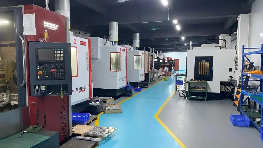
What a vertical machining center actually is
A working definition, without the brochure language.
Vertical spindle layout and what it buys you
A vertical machining center holds the spindle vertically and moves the table or the column underneath it. The workpiece sits on a horizontal table, so gravity pulls chips and coolant away from the cut instead of trapping them. Operators can watch the tool engage the part, which makes first-article setup faster and mid-run checks simpler. On a horizontal machine the part usually has to be indexed to reach four faces. On a vertical machine you often reach three faces in one setup.
The trade-off is chip evacuation on deep pockets and the limited reach of a downward-pointing tool into undercuts. A vertical spindle cannot get under a feature the way a right-angle head or a horizontal spindle can. If your part has deep blind cavities, side-entry holes, or features on the bottom face that must be machined in the same setup as the top, plan for a second operation or a different machine.
Tool magazines and automatic tool changers are what separate a machining center from a manual mill. A typical magazine holds enough tools to run roughing, semi-finishing, drilling, tapping, and boring without an operator touching the spindle. That is the reason the process holds repeatability across a run: the same tool, same offset, same path every cycle.
- 1Good fitPrismatic parts with features on the top and sides
- 2Good fitPlate work with many holes, slots, and pockets
- 3Watch outDeep blind pockets where chips pack at the bottom
- 4Watch outUndercuts and side-entry holes needing a right-angle head
Choosing 3-axis, 4-axis, or 5-axis for the job
Three-axis work covers the majority of precision parts: a flat or simple contoured part machined from one direction. If every feature is reachable from +Z, adding rotary axes only adds setup complexity and cost. We keep 27 three-axis machines for exactly this class of work, including parts up to 4,000 mm long.
Four-axis adds a rotary table, usually about a horizontal A or B axis. This is the right answer when a part has features on four sides at fixed angles: a manifold block, a housing with bolt patterns on each face, a shaft with cross-drilled holes. One rotation indexes the part, the spindle keeps cutting, and you avoid three separate fixtures and three chances to lose datum.
Five-axis simultaneous motion lets the tool tilt relative to the part. That matters for contoured surfaces, deep cavities with tapered walls, and features on faces that are not square to each other. It also shortens the tool overhang, because you can angle the tool into a corner instead of reaching straight down with a long, flexible cutter. Our 16 simultaneous 5-axis centers handle the parts where this is the difference between holding ±0.005 mm and chasing chatter.
The decision rule is simple. Count the number of distinct tool approach directions the part needs. One direction means 3-axis. Two to four fixed directions mean 4-axis. A continuously changing direction, or a surface that must be cut in one pass, means 5-axis.
- 13-axisAll features reachable from one direction; flat and simple contoured parts
- 24-axisFixed-angle features on four faces; blocks, housings, cross-drilled shafts
- 35-axisContoured surfaces, deep tapered cavities, non-square faces
- 4RuleCount the tool approach directions the part needs
Part features mapped to the right machine
Use this as a first pass. Final call depends on tolerance, finish, and quantity.
| Part feature | Best fit | Why |
|---|---|---|
| Flat plate, holes and slots | 3-axis | All features open to the spindle |
| Housing with four face patterns | 4-axis | One index replaces three setups |
| Impeller, blade, contoured vane | 5-axis | Tool tilts to follow the surface |
| Deep blind pocket, narrow floor | 4-axis or EDM | Vertical tool cannot clear chips |
| Cross-drilled shaft | 4-axis | Rotary table indexes between holes |
| Undercut on an internal bore | Right-angle head or EDM | Downward tool cannot reach |
| Large frame up to 4,000 mm | 3-axis gantry style | Long travel, stable table |
| Small precision insert, tight form | 5-axis or 3-axis | Short tools, high spindle speed |
Holding tolerance and surface finish in production
Tolerance on a vertical machining center comes from three places: machine geometry, thermal stability, and the setup. A machine that is square to itself will still drift if the shop swings in temperature or if the fixture lets the part move under cutting load. We hold ±0.005 mm (±0.0002 in) on parts that are set up and fixtured for it, and we inspect 100% before shipment, but the fixture design has to support the number you wrote on the drawing.
Surface finish follows the tool and the stepover more than the machine brand. A sharp, balanced cutter at the right feed per tooth gives Ra 0.8–1.6 μm without extra work. Pushing to Ra 0.2–0.8 μm usually means a separate finishing pass with a smaller stepover, a wiper insert, or a change in tool path strategy, and it adds cycle time. Ask for the finish the function needs, not the tightest number available.
Wall thickness and aspect ratio decide whether the part survives the cut. Thin floors ring and deflect. Tall thin walls push away from the cutter. When a feature is under about 1 mm thick over a long span, the limiting factor is often the part, not the machine, and the answer may be to leave support material, machine in two stages, or switch to a process with lower cutting force.
Quantity changes the plan as well. A single prototype can be machined from a near-net block with generous stock. A 10,000-part run justifies a soft jaw set, a dedicated fixture, and a probe routine that finds the datum on every cycle. Same machine, different application.
- 1Tolerance driverMachine geometry, thermal stability, and fixture rigidity
- 2Finish driverTool geometry, stepover, and number of finishing passes
- 3LimitThin walls and floors deflect before the machine runs out of accuracy
- 4QuantityDrives fixture design, not the choice of machine class
Which materials behave well on a vertical center
Aluminum is the easiest case: 6061, 7075, 2024, and 6082 all cut fast with sharp tooling and give a predictable finish. They also move with heat, so a heavy roughing cut followed by a finish pass on a hot part will not hold a tight tolerance. Let the part cool, then finish.
Stainless and steel are slower but well suited to the process. 303 and 304, 17-4PH, 4140, and 4340 all machine cleanly on a rigid vertical center with the right speeds and coolant. Tool wear is the variable to manage, not the machine. Titanium and Inconel are where the application gets hard: low thermal conductivity keeps heat in the cut, so tool life drops and the process needs lower speeds, higher coolant pressure, and a rigid setup.
Plastics behave differently again. POM, PEEK, and ABS cut easily but hold heat, and a light part can lift off the fixture. Vacuum fixturing or a soft jaw with a light clamp solves most of it. Plastics also move after machining, so a tolerance check should wait until the part has settled.
If your material is not on this list, send the grade. The answer usually depends on hardness, chip behavior, and whether the material work-hardens.
- 1Easy6061, 7075, 6082 aluminum; brass and copper alloys
- 2Moderate303, 304, 17-4PH stainless; 4140, 4340 steel
- 3Hard on toolingTitanium TC4, Inconel; needs low speed and high coolant pressure
- 4Different rulesPOM, PEEK, ABS; watch clamping force and post-machining movement
When a vertical machining center is the wrong choice
The process has clear edges. Very high volumes of a small, simple part often go to die casting, injection molding, or stamping, where the per-part cost drops far below any milling operation. A vertical machining center is not a volume process for simple geometry; it is a precision process for geometry that needs metal removed accurately.
Parts that are essentially rotational belong on a lathe or a mill-turn center, not a vertical mill. A shaft with a single turned diameter and one cross hole is faster on a mill-turn machine that turns and mills without a second setup. We run 16 mill-turn centers for exactly this reason.
Large flat parts with a single face feature may be cheaper on a surface grinder or a dedicated drill station if tolerance is loose. And any part whose critical feature cannot be reached from a downward tool without a special head is a candidate for EDM, a horizontal machine, or a redesign that makes the feature accessible.
The honest answer is that the application vertical machining center fits best is the middle of the range: moderate to tight tolerance, mixed features, low to medium volume, and a part that must be delivered in days rather than months.
- 1Choose another processHigh-volume simple parts: casting, molding, stamping
- 2Choose another processMostly rotational parts: lathe or mill-turn
- 3Choose another processFeatures a downward tool cannot reach: EDM or horizontal
- 4Best fitMixed features, tight tolerance, low to medium volume
Common questions from engineers and buyers
What is the largest part you can run on a vertical machining center?
Our long-travel machines handle up to 4,000 mm in the longest dimension, with travel of 4,000 × 400 × 150 mm. Other centers cover 750 × 1,150 × 550 mm, 600 × 600 × 600 mm, and smaller work envelopes.
If the part exceeds the travel, we will tell you at the quote stage rather than after you place the order. In some cases the part can be split or the setup re-planned, but that changes the design and should be decided early.
Can you hold ±0.005 mm on every feature?
We hold ±0.005 mm on features that are set up and fixtured to support it. Not every dimension on a part needs that tolerance, and writing it on every feature raises cost without improving function.
Mark only the critical dimensions. A good drawing tells us where the tolerance matters, and we will tell you if a feature cannot hold it without a fixture change or a process change.
How do you handle parts with features on five sides?
We use 4-axis and 5-axis machines, or a 3-axis machine with a tombstone fixture that indexes the part between operations. The choice depends on how many features are on the non-primary faces and how tight their tolerances are.
If a single setup can reach all five faces with a 5-axis center, that is usually the most accurate route because it avoids re-datuming between operations.
Do you inspect every part or sample them?
We inspect 100% before shipment, with raw material checks, in-process monitoring, and a final inspection. Inspection reports are available on request.
For high-volume runs we can set up a probing routine that checks critical features on every cycle, so an out-of-tolerance part is caught at the machine rather than at final inspection.
What is the lead time for a machined part?
We return a quotation and a free DFM analysis within 12 hours. Production can start within 24 hours of approval, and parts ship in 3–5 days for typical work.
Complex parts, special material, or a finish like hardcoat anodizing add time. We will state the schedule in the quote rather than promise a date we cannot hold.
Can you machine from a customer-supplied blank or casting?
Yes. We machine from bar stock, plate, near-net forgings, and castings. For a casting, the first operation usually establishes the datum, so the drawing should identify which surfaces are as-cast and which are machined.
If the casting has variable stock, we will say so before quoting, because it affects fixture design and cycle time.
Send the drawing and get a process answer, not a form letter
Upload your files and an engineer reviews the geometry, material, and tolerance, then comes back with a quote and a free DFM analysis within 12 hours. No minimum order quantity, from one prototype to 10,000+ parts. Uploads stay confidential and an NDA is available on request.
12-hour quoteFree DFM analysisNo minimum order quantityNDA on request









