CNC Knowledge: Mass production of large gears

Photo WeChat_20240830143241.jpg

Transmission components used in wind turbines (WTG for short) are all high-load equipment. Static and dynamic loads will be reflected in the pitch, roll and yaw movements of the tower top and in the structural deformation of the entire drive chain. Various dynamic reactions occur on the transmission components: spontaneous vibrations of the rotor blades, […]

Content Navigation

Transmission components used in wind turbines (WTG for short) are all high-load equipment.

Static and dynamic loads will be reflected in the pitch, roll and yaw movements of the tower top and in the structural deformation of the entire drive chain.

Various dynamic reactions occur on the transmission components: spontaneous vibrations of the rotor blades, load changes as each blade rotates, and inconsistent air turbulence acting on the rotor.

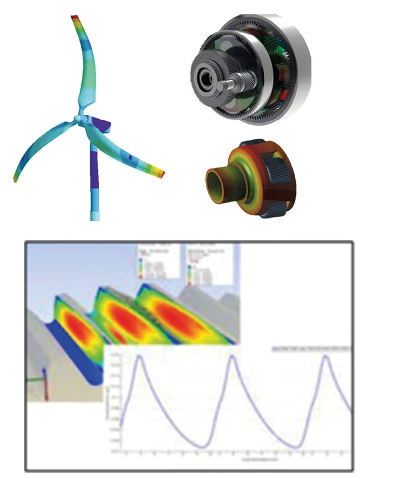
All of this can lead to distortion of transmission components and torque fluctuations. The fluctuating torque will far exceed the rated torque value in an instant. Figure 1 shows the load-induced deformation of the rotor, tower, and transmission.

Figure 1: Image showing load-induced transmission deformation (Image source: FVA, Workbench)

Wind turbine drives must be able to withstand static and dynamic loads for decades. Only with modern simulation methods and knowledge of transmission loads can transmission components be optimized to ensure a service life of 20 or 25 years with a utilization rate of 98%.

In addition to advances in simulation tools, advances in materials science for high-purity steel have also contributed to the success of the driveline.


method

Only according to the structural deformation caused by the load can the design engineer set the optimal topography of the tooth surface of each gear, so as to ensure that the pressure when contacting the tooth surface teeth does not exceed the permissible range of material parameters under various load conditions. During production, it is necessary to ensure that the shape of the tooth surface is manufactured accurately. Figure 2 shows a typical modification of a tooth surface.

Photo WeChat_20240830143246.jpg

Figure 2: Typical change in gear tooth surface

Due to the large modulus and width of teeth, form grinding has become the standard method for grinding hard tooth surfaces, allowing a high degree of freedom in tooth surface design.

Being able to change the tooth surface in actual production is a prerequisite for gear design.

Gear production software for Hofler’s RAPID cylindrical gear grinding machines helps design engineers convert expected tooth surface shapes into feasible tooth surface geometries.

The simulation of the system can therefore be carried out under realistic conditions. This prerequisite also facilitates production, as it eliminates the need for an iterative process between design and production to determine whether the gear actually produced meets the required precision requirements.


production ready process

Cost pressure and production growth often lead to process optimization, and ultimately the processing technology becomes powerful and efficient. For the mass production of large gears, the process level and production efficiency of machine tools play equally important roles. Machine tool temperature stability is essential for both. The development of RAPID series gear grinding machines began 20 years ago. Since then, experience has been accumulated and optimizations have been carried out several times.

But the frame and the column of the machine have never changed. They are always made of mineral cast iron.

This includes quartz particles, quartz sand and mineral dust, as well as a small amount of epoxy resin glue. This material gives high-precision grinding machines exceptional material properties: low thermal conductivity, high thermal capacity and ten times greater thermal attenuation than gray cast iron.

Based on this, the dimensional accuracy of large gears within a narrow tolerance range can be guaranteed regardless of the processing time. Excellent damping characteristics ensure high dynamics of the CNC axes, a prerequisite for efficient production.


Gear Alignment Solutions

Heat treatment deformation should be detected before machining, so that the grinding process can be designed to avoid unnecessary “empty tool strokes” and microstructural damage caused by excessive tool feed. To do this, you must move the stylus while detecting the maximum margin.

But what if the maximum tolerance is at the root of the tooth, at the top of the tooth, at the top or at the bottom of the tooth?

The greater the modification required to the tooth flank, the more problematic machining becomes. Extended alignment analysis provides a solution. During the analysis, several measurement points can be defined (see Figure 3). At the end, the position of the grinding wheel for uniform grinding can be calculated from the measurements.

Photo WeChat_20240830143251.jpg

Figure 3: Example of 5 points Example of 9 points Different positions of the measuring points for centering

Figure 4 shows the principle using a single tooth as an example. The unmodified nominal tooth profile is the starting point for assessing tolerances. The margin is the difference between the position measured during measurement and the unmodified position of the tooth profile.

The upper left of Figure 4 shows a single point measurement as an example. When a multi-point measurement is performed, the margin position is different. There is an inclined line segment between two measurement points and a parabola between three measurement points.

Photo WeChat_20240830143254.jpg

Figure 4: Removal of material and material

To determine the material removal, the existing stock and the nominal profile of the tooth to be machined must be taken into account (see lower left part of Figure 4). It is clear that material removal is evolving. If grinding is done in this manner, only the upper left portion will be ground in the first few passes and no grinding shrinkage will occur on the right tooth surface.

In order to minimize the number of passes for grinding the tooth gap, the allowance can be cycled in such a way that the maximum allowance on the left and right tooth surfaces is consistent and its value is as small as possible. Here it is necessary to ensure that the material removal rate is not lower than the minimum value (see the lower right part of Figure 4). With this centered position, the left and right sides can be ground in the first few passes.

The more tooth gaps on the circumference and tooth width are used to calculate the centering position, the closer the grinding allowance for the current thermal deformation is to the minimum grinding allowance. The smaller the grinding allowance, the shorter the processing time.

Photo WeChat_20240830143257.jpg

Figure 5: Optimized process parameters

Process Design Solutions

Since the more reliable the stock assessment, the more likely it is that maximum removal will be achieved, and the number of passes required to grind each tooth space can be determined automatically using different numbers of strokes. This avoids unnecessary passes and material removal beyond the feed limits. Because the number of tool passes will be automatically increased for tooth spaces with large margins.

All measurement data regarding stock and number of passes is presented to the operator (see Figure 5). Rather than blindly relying on algorithms, Gear Production software’s digital assistance systems provide optimal support to the operator.


Archiving and quality assurance solutions

After the grinding process, the gears can still be automatically measured directly on the grinding machine. The correction values ​​of machine tool settings generated based on the report can minimize production deviations as much as possible. Since we are machining tooth surface geometries that can actually be produced, there is no need to use an approximate scheme to calculate correction values: the algorithm will produce accurate values.

In principle, it does not matter whether the measurement results come from an online inspection system of the gear grinding machine or from a gear measuring center. In both cases, if corrections are necessary, the operator is informed before processing the next part (see Figure 6). The different deviations are displayed using the color display of the traffic lights (green, yellow and red) and their meaning is very clear.


automation

Planetary gears weighing up to 2.5 tonnes are extremely common in wind turbines. Automated systems are well suited to this type of machinery. By cooperating with users, although the processing of large-sized wind gears is more difficult than that of mass-produced small gears, appropriate automation solutions can be adopted. As the part is too heavy, it is recommended to use a chassis type loading and unloading device. In order to ensure that the automation system can be connected to the machine tool, it is necessary to adjust the protective cover of the machine tool and add protective devices in accordance with the Machinery Directive regulations. In addition to workpiece processing, the safety measures of the automatic loading and unloading device of the gear grinding machine should be strengthened to ensure data consistency and precise clamping and release of workpieces on the workpiece table. machine tool.

Once the part is clamped on the support, the measuring system integrated into the machine tool detects runout and axial concentricity. If the measured value exceeds the set tolerance, the position will be changed and tightened. If the clamping tolerances are still not met, the part is unloaded from the machine and series production is interrupted.

Photo WeChat_20240830143304.jpg

Figure 6: Visualization of production gaps


in conclusion

Efforts to reduce production costs and improve process productivity have, on the one hand, reduced the distance between development and design, and on the other hand, broken the restrictions imposed on mass production of large gears.

Mass production of large gears cannot simply be applied to designs from other sectors, such as the automotive industry. However, the principles are the same, and reliable gear design and processing solutions can create powerful processing technology.

Daguang focuses on providing solutions such as precision CNC machining services (3-axis, 4-axis, 5-axis machining), CNC milling, 3D printing and rapid prototyping services.

Picture of JinShui Chen

JinShui Chen

Rapid Prototyping & Rapid Manufacturing Expert

Specialize in CNC machining, 3D printing, urethane casting, rapid tooling, injection molding, metal casting, sheet metal and extrusion

Pressroom

Recent Posts

Welcome to GreatLight Metal,Maximum Processing Size 4,000 mm

Precision Machining CNC Quote Online

Loading file

Upload Click here to upload or drag and drop your model to the canvas.

The model is too large and has been resized to fit in the printer's build tray. [Hide]

The model is too large to fit in the printer's build tray. [Hide]

The model is too large, a fitting printer is selected. [Hide]

The model is too small and has been upscaled. [Hide]

Warning: The selected printer can not print in full color [Hide]

Warning: obj models with multiple meshes are not yet supported [Hide]

Warning: Unsupported DXF entity  [Hide]

Warning: could not arrange models [Hide]


File Unit:      
Scale:
%
L × W × H:
X: × Y: × Z:  cm 
Rotation:
X: ° Y: °  


Model Stats:

Material Volume: cm3
Support Material Volume: cm3
Box Volume: cm3
Surface Area: cm2
Model Weight: g
Model Dimensions:
x x cm
Number of Polygons:
Number of Shapes:
Total Path: cm
⚡ Instant Quote for Precision Manufacturing

Submit your design files (STEP/IGES/DWG) and receive a competitive quote within 1 hour, backed by ISO 9001-certified quality assurance.

📋 How It Works

  1. Upload & SpecifyShare your 3D model and select materials (Aluminum/Stainless Steel/Titanium/PEEK), tolerances (±0.002mm), and surface treatments.

  2. AI-Powered AnalysisOur system calculates optimal machining strategy and cost based on 10+ years of automotive/aerospace data.

  3. Review & ConfirmGet a detailed breakdown including:
    - Volume pricing tiers (1-10,000+ units)
    - Lead time (3-7 days standard)
    - DFM feedback for cost optimization

Unit Price: 

Loading price
5 Axis CNC Machining Equipment
4 Axis CNC Machining Equipment
3 Axis CNC Machining Equipment
CNC Milling & Turning Equipment
Prototype and Short-Run Injection Moldings Exact plastic material as final design
Volume Metal Die Casting Services - Precision Cast Parts
Bridge the Gap From Prototype to Production – Global delivery in 10 days or less
Custom high-precision sheet metal prototypes and parts, as fast as 5 days.
Custom Online 3D Printing Services
Design Best Processing Method According To 3D Drawings
Alloys Aluminum 6061, 6061-T6 Aluminum 2024 Aluminum 5052 Aluminum 5083 Aluminum 6063 Aluminum 6082 Aluminum 7075, 7075-T6 Aluminum ADC12 (A380)
Alloys Brass C27400 Brass C28000 Brass C36000
Alloys Stainless Steel SUS201 Stainless Steel SUS303 Stainless Steel SUS 304 Stainless Steel SUS316 Stainless Steel SUS316L Stainless Steel SUS420 Stainless Steel SUS430 Stainless Steel SUS431 Stainless Steel SUS440C Stainless Steel SUS630/17-4PH Stainless Steel AISI 304
Inconel718
Carbon Fiber
Tool Steel
Mold Steel
Alloys Titanium Alloy TA1 Titanium Alloy TA2 Titanium Alloy TC4/Ti-6Al 4V
Alloys Steel 1018, 1020, 1025, 1045, 1215, 4130, 4140, 4340, 5140, A36 Die steel Alloy steel Chisel tool steel Spring steel High speed steel Cold rolled steel Bearing steel SPCC
Alloys Copper C101(T2) Copper C103(T1) Copper C103(TU2) Copper C110(TU0) Beryllium Copper
Alloys Magnesium Alloy AZ31B Magnesium Alloy AZ91D
Low Carbon Steel
Alloys Magnesium Alloy AZ31B Magnesium Alloy AZ91D
ABS Beige(Natural) ABS Black ABS Black Antistatic ABS Milky White ABS+PC Black ABS+PC White
PC Black PC Transparent PC White PC Yellowish White PC+GF30 Black
PMMA Black PMMA Transparent PMMA White
PA(Nylon) Blue PA6 (Nylon)+GF15 Black PA6 (Nylon)+GF30 Black PA66 (Nylon) Beige(Natural) PA66 (Nylon) Black
PE Black PE White
PEEK Beige(Natural) PEEK Black
PP Black PP White PP+GF30 Black
HDPE Black HDPE White
HIPS Board White
LDPE White
This is a finish of applying powdered paint to the components and then baking it in an oven, which results in a stronger, more wear- and corrosion-resistant layer that is more durable than traditional painting methods.
No coating required, product’s natural color!
This is a finish of applying powdered paint to the components and then baking it in an oven, which results in a stronger, more wear- and corrosion-resistant layer that is more durable than traditional painting methods.
This finishing option with the shortest turnaround time. Parts have visible tool marks and potentially sharp edges and burrs, which can be removed upon request.
Sand blasting uses pressurized sand or other media to clean and texture the surface, creating a uniform, matte finish.
Polishing is the process of creating a smooth and shiny surface by rubbing it or by applying a chemical treatmen
A brushed finish creates a unidirectional satin texture, reducing the visibility of marks and scratches on the surface.
Anodizing increases corrosion resistance and wear properties, while allowing for color dyeing, ideal for aluminum parts.
Black oxide is a conversion coating that is used on steels to improve corrosion resistance and minimize light reflection.
Electroplating bonds a thin metal layer onto parts, improving wear resistance, corrosion resistance, and surface conductivity.
This is a finish of applying powdered paint to the components and then baking it in an oven, which results in a stronger, more wear- and corrosion-resistant layer that is more durable than traditional painting methods.
Please provide additional text description for other surface treatment requirements!
Material
Material
  • CNC Metals
    • Aluminum
    • Brass
    • Stainless steel
    • Inconel718
    • Carbon Fiber
    • Tool Steel
    • Mold Steel
    • Titanium
    • Alloy Steel
    • Copper
    • Bronze
    • Low Carbon Steel
    • Magnesium
  • CNC Plastics
    • ABS
    • PC
    • PMMA (Acrylic)
    • PA (Nylon)
    • PE
    • PEEK
    • PP
    • HDPE
    • HIPS
    • LDPE
Printer
Printer
  • CNC Metals
    • 5 Axis CNC Machining
    • 4 Axis CNC Machining
    • 3 Axis CNC Machining
    • CNC Milling & Turning
    • Rapid Tooling
    • Metal Die Casting
    • Vacuum Casting
    • Sheet Metal Fabrication
    • SLA 3D Printing
    • SLS 3D Printing
    • SLM 3D Printing
  • Rapid Prototyping
    • Design Best Processing Method According To 3D Drawings
Post-processing
Post-processing
Finalize
The world's first CNC machining center that dares to provide free samples!

Free for first product valued at less than $200. (Background check required)

Precision Machining CNC Quote Online

15 Years CNC Machining Services

When you’re ready to start your next project, simply upload your 3D CAD design files, and our engineers will get back to you with a quote as soon as possible.
Scroll to Top

ISO 9001 Certificate

ISO 9001 is defined as the internationally recognized standard for Quality Management Systems (QMS). It is by far the most mature quality framework in the world. More than 1 million certificates were issued to organizations in 178 countries. ISO 9001 sets standards not only for the quality management system, but also for the overall management system. It helps organizations achieve success by improving customer satisfaction, employee motivation, and continuous improvement. * The ISO certificate is issued in the name of FS.com LIMITED and applied to all the products sold on FS website.

GreatLight Metal ISO 9001 certification successfully renewed
✅ ISO 9001:2015
GreatLight Metal ISO 9001 certification successfully renewed ZH

ISO 13485 certificate

ISO 13485 is an internationally recognized standard for Quality Management Systems (QMS) specifically tailored for the medical device industry. It outlines the requirements for organizations involved in the design, development, production, installation, and servicing of medical devices, ensuring they consistently meet regulatory requirements and customer needs. Essentially, it's a framework for medical device companies to build and maintain robust QMS processes, ultimately enhancing patient safety and device quality.

GreatLight Metal Technology Co., Ltd Has Obtained Multiple Certifications (3)
GreatLight Metal Technology Co., Ltd Has Obtained Multiple Certifications (4)

ISO 27001 certificate

ISO/IEC 27001 is an international standard for managing and processing information security. This standard is jointly developed by the International Organization for Standardization (ISO) and the International Electrotechnical Commission (IEC). It sets out requirements for establishing, implementing, maintaining, and continually improving an information security management system (ISMS). Ensuring the confidentiality, integrity, and availability of organizational information assets, obtaining an ISO 27001 certificate means that the enterprise has passed the audit conducted by a certification body, proving that its information security management system has met the requirements of the international standard.

GreatLight Metal Technology Co., Ltd Has Obtained Multiple Certifications (1)
GreatLight Metal Technology Co., Ltd Has Obtained Multiple Certifications (2)

IATF 16949 certificate

IATF 16949 is an internationally recognized Quality Management System (QMS) standard specifically for the automotive industry. It builds upon the foundation of ISO 9001 and adds specific requirements relevant to automotive production and service parts. The goal is to enhance quality, improve processes, and reduce variation and waste within the automotive supply chain.

Automotive Industry Quality Management System Certification_01
Automotive Industry Quality Management System Certification_00

Get The Best Price

Send drawings and detailed requirements via Email:info@glcncmachining.com
Or Fill Out The Contact Form Below:

All uploads are secure and confidential.