Recently, friends who are not professional in the field of gears but are involved in this field asked a question: How to use less professional vocabulary to explain what gears are? Some names on the English drawings are noted in passing. Let’s try talking about gears this way. It’s a bit long, so friends who want to know more can be patient and take it down.
Cars, clocks, can openers, and many other devices use gears in their mechanisms to transmit power through rotation. A gear is a circular mechanical device (some gears are also non-circular) with teeth that mesh to transmit rotation on an axis. They are an extremely valuable piece of machinery due to their wide range of applications.
What is a gear?
A gear is a wheel with teeth on its circumference. Gears are usually grouped together and are used to transmit rotation from the shaft of one gear to the shaft of another gear. The teeth of a gear on one shaft mesh with the teeth of a gear on the other shaft, creating a relationship between the rotation of the two shafts. When one axis rotates, the other axis also rotates. Two different sized gears will spin their two axes at different speeds, you will learn more about this, as well as the different types of gears and where they are used.
Why use gears?

Gears are a very useful transmission mechanism for transmitting rotation from one shaft to another. As I mentioned before, you can use gears to change the output speed of the shaft. Let’s say you have an engine that runs at 100 rpm and you want it to only run at 50 rpm. You can use a gear system to reduce speed (and also increase torque) so that the output shaft turns at half the speed of the motor. Gears are often used in high-load situations because the teeth of the gear allow finer, more discrete control of shaft movement, an advantage that gears have over most pulley systems. Gears can be used to transmit rotation from one axis to another, and special types of gears can transmit motion to non-parallel axes.
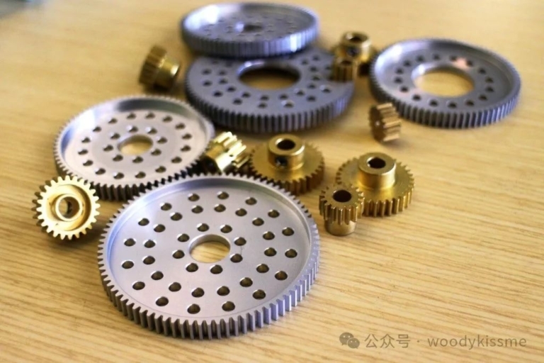
gear parts

Teeth – The teeth of a gear, a serrated surface that projects outward from the circumference of a gear and is used to transmit rotation to other gears. The number of gear teeth must be an integer. A gear will only transmit rotation if its teeth mesh and have the same tooth profile.
Axis – The central axis of the gear, a point when viewed from the front.
Pitch Circle – The pitch circle of a gear, which is a circle measuring the size of a gear.
Pitch Diameter – The pitch circle diameter two gears must have the same pitch diameter to mesh.
Circular picth ——The pitch of the gear, that is, the length of the arc from the center of one tooth to the center of the other tooth on the pitch circle
Pressure angle——The pressure angle of the gear, how to express this in simple terms? When a pair of gears mesh (contact), the angle between the direction of force and the direction of speed of travel doesn’t seem to be well understood, so let’s leave it at that.
Calculate gear ratio

As mentioned earlier, gears can be used to reduce or increase the speed or torque of a drive shaft. In order to drive the output shaft at the required speed, a gear system with a specific speed ratio is needed to produce that speed.
The system speed ratio is the ratio of the input shaft speed to the output shaft speed. There are many ways to calculate the gear ratio in a two-speed system. The most common method is to determine the number of teeth (N) on each gear. To calculate the gear ratio (R), the formula is: R=N2/N1
Where N2 represents the number of teeth of the gear connected to the output shaft, and N1 represents the number of teeth of the gear connected to the input shaft. The left gear in the first picture above has 16 teeth and the right one has 32 teeth. If the left gear is the input shaft, the ratio is 32:16, which can be simplified to 2:1. This means that for 2 revolutions of the left gear, the right gear will make one revolution.
The gear ratio can also be used to determine the torque output of the system. Torque is defined as the tendency of an object to rotate about its axis; essentially the rotational power of the axis. A shaft with more torque can turn larger objects. The gear ratio R is also equal to the ratio of the output shaft torque to the input shaft torque. In the example above, although the 32-tooth gear rotates more slowly, it produces twice the rotational power of the input shaft.
Gear type

There are many types of gears and gear mechanisms, and certainly not all of them will be covered here. We’ll start with some of the simplest gears and gear mechanisms and then move on to some of the more complex and interesting gears and gear mechanisms.
spur gear

Spur gears are the most common and simplest type of gear. Spur gears are used to transmit motion from one axis to another parallel to it. The tooth grooves on the two upper end faces of the spur gear face each other, and the shape and position are exactly the same. When two adjacent spur gears mesh, they rotate in opposite directions.
gearbox

Is this a bit familiar? It can hardly be called a gearbox. The gearbox receives rotation from the input shaft (usually the motor shaft) and changes the speed and power of the input shaft through a series of gears to the required speed. or torque rotates the output shaft. Transmissions are generally classified based on their overall speed ratio (the ratio of input shaft speed to output shaft speed).
bevel gear

A bevel gear is a gear used to transmit power from one shaft to another non-parallel shaft. Bevel gears have angled teeth, which actually makes the shape of their “pitch diameter” conical. This is why most bevel gears are classified based on the distance from the large end face of the gear to the tip of the imaginary cone that would form if the gear teeth protruded. For two bevel gears to mesh, each imaginary bevel tip must intersect at the same vertex. When two bevel gears are the same size and rotate an axle at a 90 degree angle, they are called “helical gears.”
rack

The rack and pinion converts the rotational motion of the gear (pinion) into the linear motion of the rack. The pinion is like any other spur gear in that it meshes with the rack (a track with teeth). As the gear turns, the rack slides continuously.
internal gear

Internal gears are gears with teeth on the inside rather than the outside. Internal gears can be used to reduce the space a transmission takes up or to allow something to pass through the center of a shaft as the gear rotates. Unlike ordinary spur gears, internal gears rotate in the same direction as ordinary spur gears. In most cases, internal gears are used in planetary gearboxes. Let’s take a look at planetary gearboxes.
planetary gearbox

A planetary gearbox is a special type of gearbox that uses internal gears. The main components of a planetary gearbox include the sun gear, which is located in the center of the gearbox and is usually connected to the input shaft of the system. The sun gear rotates several planetary gears, which simultaneously rotate a large internal gear, called a ring gear. Planetary gears are usually held by brackets that prevent them from rotating around the planetary gear. Planetary gearboxes can handle higher loads than most reducers because the load is distributed across all planetary gears rather than just one spur gear. These gearboxes are ideal for large reductions in tight spaces, but can be expensive due to their complex design and require good lubrication.
Worm gear

A worm gear is a gear driven by a worm, a small screw-shaped component that meshes with the gear. The gear rotates about an axis perpendicular to the worm, but not in the same plane as the worm. For each revolution of the worm, the gear turns one tooth. This means that the gear ratio of the worm gear is always N:1, where N is the number of teeth of the gear. While most gears have a circular pitch, worm gears have a linear pitch, which is the distance from one revolution to the next in the propeller.
Therefore, worm gears can be used to significantly reduce the speed and increase the torque of the system in a single step and occupying very little space. A worm gear mechanism can achieve a gear ratio of 40:1 using only a 40-tooth gear and a worm, whereas using a spur gear to achieve the same effect would require a pinion meshing with another gear 40 times the size.
Since the worm is helical, it is almost impossible to drive the worm gear in reverse. This means that if you try to turn the system by its output shaft (on the worm gear) rather than by its input shaft (on the worm gear), you will not succeed. not. When driven by a worm, the spiral rotates and slowly advances each tooth. If you reverse the system, the gears will push against the sides of the threads without actually rotating them. This makes worm gears very valuable in mechanical systems because the shaft cannot be manipulated by external forces and reduces backlash and backlash in the system.
Helical gears and herringbone gears

Helical gears are a more efficient gear. The teeth are at an angle to the axis of rotation, so they end up being curved around the gear rather than straight up and down like a spur gear. Helical gears can be installed between parallel shafts, but can also be used to drive non-parallel shafts provided the inclined teeth mesh.
The teeth of spur gears mesh all at once, that is, the entire tooth surface of one gear is in full contact with the tooth surface of the adjacent gear immediately after meshing, while the teeth of the helical gears gradually slide into each other. Helical gears are therefore more suitable for high loads and high speeds. The disadvantage of helical gears is that they require thrust bearings because when the teeth of the helical gear mesh, they create an axial thrust that pushes the gear along its axis of rotation.
This problem can be solved with a herringbone gear, which is essentially two helical gears connected together by teeth at opposite angles. This eliminates the lateral forces produced by the helical gear because the axial force on one side of the herringbone gear cancels the force on the other side. Herringbone gears are more difficult to manufacture than helical gears due to their geometry.
Cage gears and pin gears

Cage gears and pin gears are an easier type of gear mechanism to make because they can be made inexpensively from wooden boards and dowels. However, they are not well suited to high speed or high load situations, as they typically have significant clearance and headroom. Cage gears and pin gears are mainly used to transfer rotation between vertical shafts. A pin gear is essentially a disk with short pins extending from it (forming a spur gear) or across its surface parallel to the axis of rotation (forming a bevel gear). The pins of these gears act like teeth and touch each other to turn each gear. A cage gear consists of two discs between which there is a pin parallel to the axis of rotation. Cage gears can be used like worm gears because each pin on the gear contacts a pin on a regular pin gear. However, the system can be controlled from both sides.
incomplete equipment

This type of gear is a gear whose tooth profile does not extend along the pitch circle. This mangled equipment can be used for many different purposes. In some cases you may not need the entire tooth profile of the gear, as the gear may never need to rotate 360 degrees and you may have a bond, a beam or other mechanism that is part of the missing side of the gear. In other cases, you may want the broken gear to rotate 360 degrees, but you may not want it to rotate all the way to the other gear. If you spin a broken gear with half a tooth missing and its teeth mesh with a full spur gear every 30 seconds, the spur gear will spin for 15 seconds, then stay there for 15 seconds. This way you turn a continuous rotational motion into a discrete rotational motion, meaning the input shaft rotates continuously, the output shaft rotates a little, then stops, then rotates again, then stops again, and so on.
Non-circular gears

Non-circular gears, although rare in the industry, are a very interesting mechanism. The meeting diameter of the gears changes as the gears rotate, so the output speed of the system oscillates as the gears rotate. Non-circular gears can take almost any shape. If both axes of a constrained gear are fixed, then the sum of the radii of the gear at the point of meshing must always equal the distance between the two axes.
ratchet

A ratchet is a fairly simple device that allows a gear to turn in only one direction. A ratchet system consists of a gear (sometimes with teeth different from the standard shape) and a small lever or latch that rotates around a pivot point and catches in the teeth of the gear. The latch is designed and oriented such that if the gear turns one way, the gear is free to turn and the latch is pushed up by the teeth, but if the gear turns the other direction, the latch gets stuck in the gear teeth. and prevents him from moving.

Ratchets are useful in a variety of applications because they allow force to be applied in one direction but not another. These systems are common on bicycles (you pedal forward to turn the wheels, but if you pedal backwards the wheels turn freely), a few wrenches and a large winch to wind up the load.
clutch

A clutch is a device found primarily in cars and other road vehicles that is used to change the speed of an output shaft and to disconnect or connect the rotation of the output shaft. A clutch device involves at least two shafts, an input shaft driven by the power source and an output shaft driving the final device. As an example, I will explain a simple 2 speed clutch setup with reference to the image above. There are two different sized gears on the input shaft (the two blue gears on the upper shaft) and the output shaft contains two gears that mesh with the gears on the input shaft (the gears red and green) but are free to rotate. the output shaft, so they don’t drive it. The clutch plate (the blue grooved piece in the middle) sits between the two gears, turns with the output shaft and slides along it. If the clutch disc is pressed against the red gear, the output shaft will engage and rotate at the speed set by the gear ratio of that gear set (3:2). If the clutch disc is pressed against the green gear, the output shaft is driven into a different gear ratio, defined by this gear set (2:3). If the clutch disc is between the two gears, the output shaft is in neutral and will not be driven.
Clutch plates can mesh with gears in several different ways. Some clutch plates are friction engaged, with friction pads fitted to the sides of the clutch plates as well as the sides of the gears. Other clutch plates (pictured above) are toothed and mesh with specific teeth on the gear surface.
Differential

The gear differential is a very interesting mechanism which consists of a ring gear and four smaller bevel gears (two sun gears and two planetary gears rotating around them) which act as a planetary reduction gear. It is mainly used in cars and other vehicles because it has an input shaft that drives two output shafts (which will be connected to the wheels) and allows the two output shafts to rotate at different speeds when necessary. Ultimately, the average speed of each output shaft should always equal the speed of the ring gear.
If the car is turning, the two wheels will turn at different speeds. The inside wheel will turn faster than the outside wheel because it is closer to the center point of the car’s turn. If both wheels are attached to the same axle, the car will have difficulty turning: one wheel will turn slower than the other, causing drag. Through a differential gear mechanism, the two shafts not only allow the wheels to rotate at their own speed, but are also driven by the input shaft. If one wheel spins faster than the other, the blue planetary gear simply rotates around its axis rather than remaining stationary. The planetary gears now both rotate around their axis and the output shaft (thanks to the bracket), thereby powering both wheels but allowing one wheel to spin faster than the other.
Make something with gears

Gears can be seen everywhere in toys:

Of course, gears can do much more, like this:

And yes, I didn’t expect it!

Daguang focuses on providing solutions such as precision CNC machining services (3-axis, 4-axis, 5-axis machining), CNC milling, 3D printing and rapid prototyping services.


