
Humanoid Robot Simulation Test Parts CNC: What Decides Test Validity
Simulation test parts carry the same loads, fits and sensor geometry as the production design, but in one-to-five-unit batches. This page explains how humanoid robot simulation test parts CNC actually works: which tolerances matter, which alloys behave, and when machining is the wrong process. Written for robotics engineers and hardware buyers who need a decision, not a brochure.
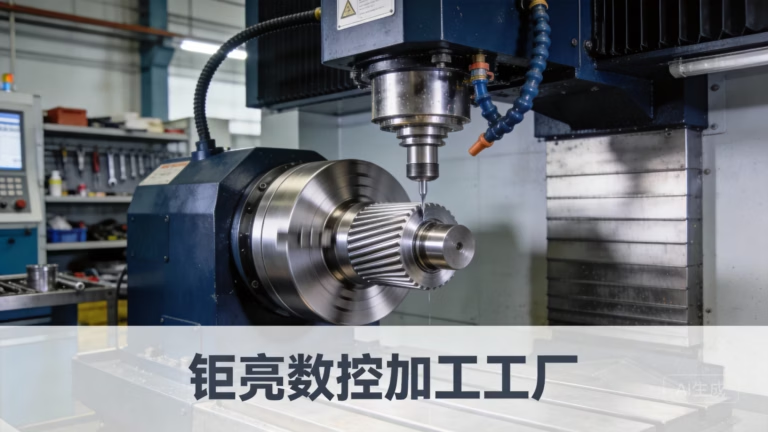
What Counts as a Simulation Test Part
A simulation test part is a machined component that goes onto a robot during validation, not onto a customer. Think knee joint housings, harmonic drive adapters, output flanges, ankle brackets, forearm links, sensor mounts. They must match the production geometry closely enough that the test result means something.
The batch size is usually one to five units. That number changes everything about how the part should be made. Tooling investment does not amortize, so casting and forging dies are out. Setup time dominates the cost. And because the part is often the only one that exists, there is no second chance if a bore comes in undersized.
Simulation work splits into two families. Kinematic parts move or locate, so their fits drive the result. Structural parts carry load or stiffness, so their material and wall thickness drive the result. A single ankle assembly can contain both, which is why humanoid robot simulation test parts CNC work rarely fits a single machining strategy.
The test itself sets the requirement. A gait study on a treadmill may only need the linkage to move freely. A drop test at 1.5 m needs the housing to survive impact without cracking. Write down which one you are doing before you pick a tolerance.
How Tight Does a CNC Simulation Part Need to Be
A general machining tolerance of ±0.05 mm is fine for a sensor bracket or a cable routing block. Nothing on the robot cares. But bearing bores, gear meshes, dowel pin holes and anything that sets backlash usually need ±0.01 mm or better. On our five-axis centers we hold ±0.005 mm when the drawing calls for it.
The trap is specifying tight tolerance everywhere. It raises cost, extends cycle time, and buys nothing on surfaces that never touch another part. Mark the critical dimensions on the drawing. Leave the rest at a general block tolerance. Your machinist will spend the extra time where it matters.
Position tolerance matters more than size tolerance on joint housings. A bore can be perfectly round and still sit 0.03 mm off its datum, which shows up as interference on assembly. Use true position with a clear datum scheme instead of a stack of linear dimensions.
Surface finish follows the same logic. A harmonic drive interface or a sensor mounting face usually wants Ra 0.8–1.6 μm to seat flat and repeat. Cosmetic exterior surfaces can stay at Ra 1.6–3.2 μm as machined. Fine finishes down to Ra 0.2–0.8 μm are available when a sealing face needs them.
Which Alloys Survive Dynamic Testing
7075-T6 aluminum is the default for structural links and housings. It has roughly twice the yield strength of 6061-T6 and machines cleanly at high spindle speeds. The trade-off is that it is less weldable and less corrosion resistant, so it usually gets anodized.
6061-T6 is the better choice when you need a housing that is easy to machine, anodizes predictably, and does not see extreme stress. Many torso frames and electronics enclosures end up here. It is also cheaper and more available in thick plate.
Ti-6Al-4V (TC4) shows up where weight and fatigue life both matter: ankle links, load cells, high-cycle joint components. It cuts slowly, around 40–60 m/min surface speed with carbide, and it springs back during finishing. Leave more stock for the finish pass than you would on aluminum.
17-4PH stainless is common for shafts, pins and gear adapters that need hardness and corrosion resistance. PEEK and carbon fiber reinforced PEEK appear in insulating or low-weight parts, but they need sharp tooling and slower feed rates to avoid delamination and melting.
- 17075-T6Structural links, housings, high strength to weight
- 26061-T6Frames, enclosures, easy machining and anodizing
- 3Ti-6Al-4VFatigue-critical joints, ankle and load paths
- 417-4PHShafts, pins, adapters needing hardness
Five-Axis Setup and Where Geometry Fails
A knee joint housing typically has bores that meet at an angle, plus a mounting face that must stay parallel to the leg axis. On a three-axis machine that means three or four setups, and every re-clamp adds error. On a five-axis center with a Ø400 mm rotary table, most of it comes off in one or two setups.
Fewer setups means fewer datum transfers, and datum transfer is where tolerance quietly disappears. That is the main reason humanoid robot simulation test parts CNC work leans on simultaneous five-axis capability rather than tight three-axis work.
Deep pockets and thin walls are the usual failure points. A 1.5 mm wall on a 60 mm tall pocket will deflect during roughing and chatter during finishing. Support it with tabs, take light finishing passes, and expect to leave 0.3–0.5 mm radial stock for the final cut.
Long reach is the other limit. A bore 120 mm deep at Ø20 mm needs a tool with a length-to-diameter ratio of six or more, which pushes deflection and taper. If the design allows, open the back of the bore or use a stepped diameter so the tool can reach without chatter.
When CNC Is the Wrong Process
If the part is a hollow shell with internal lattice and no critical fits, 3D printing wins on speed and cost. Machining it would mean removing most of the stock as chips, and the internal geometry may not be reachable at all.
If you need twenty identical units of a complex housing tomorrow, neither process is ideal. Machining gives the best material properties and finish, but twenty units still means twenty setups unless you make soft jaws or a fixture. Plan for that, or accept a longer lead time.
If the part has to be molded in the final production material, a machined prototype will not predict warp or sink marks. Use machining to validate function and fit, then move to the production process for the material-behavior study.
CNC also struggles with parts that must be one continuous piece of a material we cannot cut, such as certain high-temperature ceramics. In those cases the geometry usually gets redesigned around the process limit anyway.
Machining vs Printing vs Casting for Test Parts
Use this to pick a process before you send a drawing.
| Process | Best for | Watch out for | Typical use |
|---|---|---|---|
| 5-axis CNC | Fits, bores, load paths | Setup cost per unit | Joint housings, adapters |
| 3-axis CNC | Flat plates, simple brackets | Multiple re-clamps | Sensor mounts, cover plates |
| 3D printing | Hollow shells, lattices | Weak layer direction | Concept fit checks |
| Vacuum casting | 5–50 units, rubber-like parts | Lower strength than CNC | Grip pads, covers |
| Die casting | 1,000+ unit production | Tooling lead time | Final mass-produced housings |
Pick the Process by What the Test Measures
If the test measures fit, backlash or stiffness, machine the part in the final alloy. If the test only checks whether the shape fits together, print it and save the week.
Questions Engineers Ask Before Ordering
Can you hold ±0.005 mm on a one-off part?
Yes, on a five-axis center with the right setup and a stable material. We inspect against the drawing before shipment.
The part has to be designed for it. A thin unsupported wall will move no matter how good the machine is.
What is the smallest batch you will run?
One piece. There is no minimum order quantity, and that applies to prototypes as well as 10,000+ part runs.
For a single unit we still quote the same way: upload the model, we return a quote and a DFM analysis within 12 hours.
Which finish should a joint housing get?
Hardcoat anodizing if the surface rubs or wears. Clear anodizing if you only need corrosion resistance and a clean look.
Keep the bearing bore masked so the anodize layer does not change the fit. Anodize adds a few microns per side.
Do you sign an NDA for robot designs?
Yes. An NDA is available on request, and uploads are treated as secure and confidential.
We are certified to ISO 27001:2022 for information security, which covers how design data is handled.
How fast can test parts ship?
Production can start within 24 hours of a confirmed order, and parts typically ship in 3–5 days.
Complex five-axis parts with tight tolerances take longer. We tell you the realistic date in the quote.
Can you machine carbon fiber reinforced PEEK?
Yes. It needs sharp tooling and controlled feed rates to avoid delamination and melting.
Tell us the fiber orientation and the finished dimension, because the material springs back after cutting.
Send the Model, Get a Machining Plan
Upload your STEP file and we return a quote with DFM feedback within 12 hours. From one prototype unit to a full test campaign.
12-hour quote±0.005 mm100% inspectionNDA on request
More from the Shop Floor
We publish setup notes, tooling trials and inspection data from the factory floor.











