
01
Joint housings that bind after anodizing
Bearing bores machined to nominal, then anodized, then the bearing will not seat. The coating adds several microns. We cut bore pre-plate and control the finish so the press fit stays in spec.
GreatLight machines robot parts — joint housings, arm links, wrist flanges, base plates — on 16 simultaneous 5-axis centers. Tolerances to ±0.005 mm, from a single prototype to 10,000+ part runs.
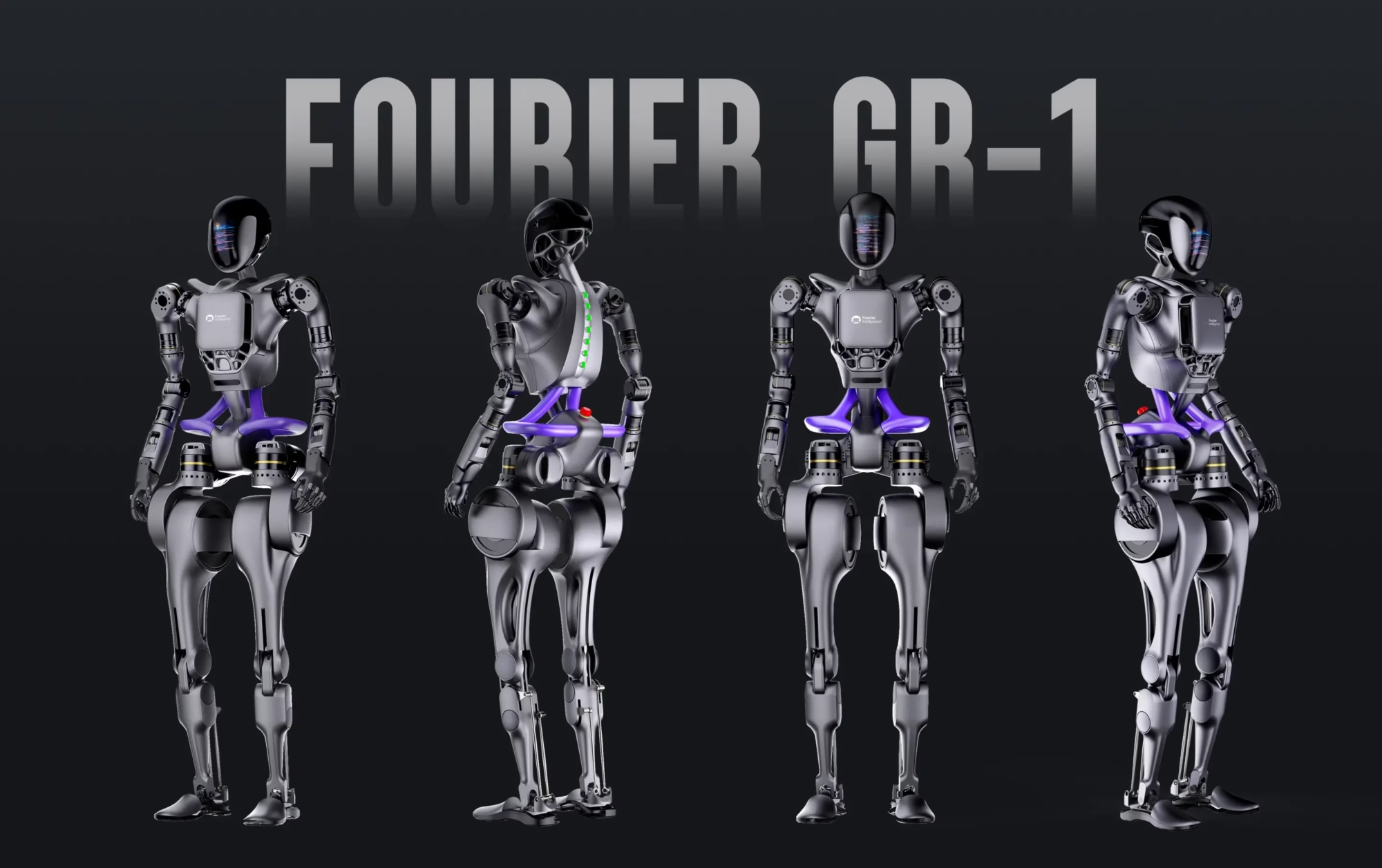
These are the failure modes we see most often when a robotics team sends a new design to a shop.
Bearing bores machined to nominal, then anodized, then the bearing will not seat. The coating adds several microns. We cut bore pre-plate and control the finish so the press fit stays in spec.
A linkage that looks fine on a drawing deflects at full reach. Thin walls, sharp internal corners, no rib. We flag the stiffness problem at DFM and suggest a geometry change before the first cut.
Each part passes inspection. Bolted together, the axes do not line up. Datum choices and hole-to-hole position matter more than any single dimension. We control position, not just size.
The prototype runs on one machine with hand work. At 500 units the process does not scale. We plan the prototype around the production process from the first quote.
5-axis milling, turning and inspection under one roof — so the datum stays the same from raw stock to finished part.

A robot joint is mostly a set of related bores and faces. Bearing seats, motor pilot, encoder mount, cable passage. If they are cut in separate setups, the stack-up shows up as backlash or a stiff axis.
Our 16 simultaneous 5-axis centers cut the bearing bore, the perpendicular mounting face and the bolt pattern in one setup. That removes the re-fixturing error. A Ø400 mm rotary table handles larger joint bodies without repositioning.
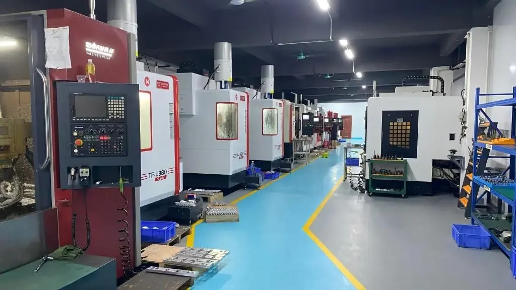
Structural robot parts are about stiffness per gram. You want the lightest link that still holds position when the arm is extended and the payload is at full reach.
We machine arm segments, adapter plates, base frames and end-effector flanges from aluminum and titanium billet. Pocketing, ribbing and wall thickness are decided together with you at DFM, not after the part is cut.
Long parts are not a problem. Our largest travel is 4,000 × 400 × 150 mm, so a single-piece arm rail does not need to be spliced.
A rough guide. The final call depends on geometry, quantity and tolerance.
| Part | Process | Why |
|---|---|---|
| Joint housing | 5-axis milling | Multiple bores and faces, one datum |
| Wrist flange | 5-axis + turning | Round body with bolt pattern |
| Arm link | 3 or 4-axis milling | Long part, features on few faces |
| Motor shaft adapter | CNC turning | Concentric diameters, tight runout |
| Base plate | 3-axis milling | Flat part, hole pattern, pockets |
| Prototype shell | 5-axis / vacuum casting | Thin walls, low quantity first |
| End-effector bracket | Mill-turn | Turning plus cross features |
| Large arm rail | 5-axis, 4,000 mm travel | One piece, no splice joint |
Six services cover most robot part programs. All run in-house.
Complex joints and housings cut in one setup. 16 simultaneous 5-axis centers.
Shafts, adapters, inserts and mill-turn parts with tight concentricity.
Functional metal and plastic prototypes before you commit to tooling.
Anodizing, plating, bead blasting, laser marking. Bore compensation handled.
Covers, brackets and enclosures that pair with machined structural parts.
Small-batch covers and shells when quantity is low and geometry is complex.
Numbers you can check a drawing against before you send it.
| Item | Range | Note |
|---|---|---|
| Tolerance | ±0.005 mm | ±0.0002 in on critical features |
| Fine finish | Ra 0.2–0.8 μm | Bearing seats and sealing faces |
| Standard finish | Ra 0.8–1.6 μm | General machined surfaces |
| As-machined | Ra 1.6–3.2 μm | Non-critical faces |
| 5-axis centers | 16 | Simultaneous, 5 sides per setup |
| Largest travel | 4,000 × 400 × 150 mm | Long rails and frames |
| Rotary table | Ø400 mm | Large joint bodies |
| Materials | Aluminum, stainless, steel, titanium, plastic | 6061-T6, 7075, TC4, 17-4PH, PEEK |
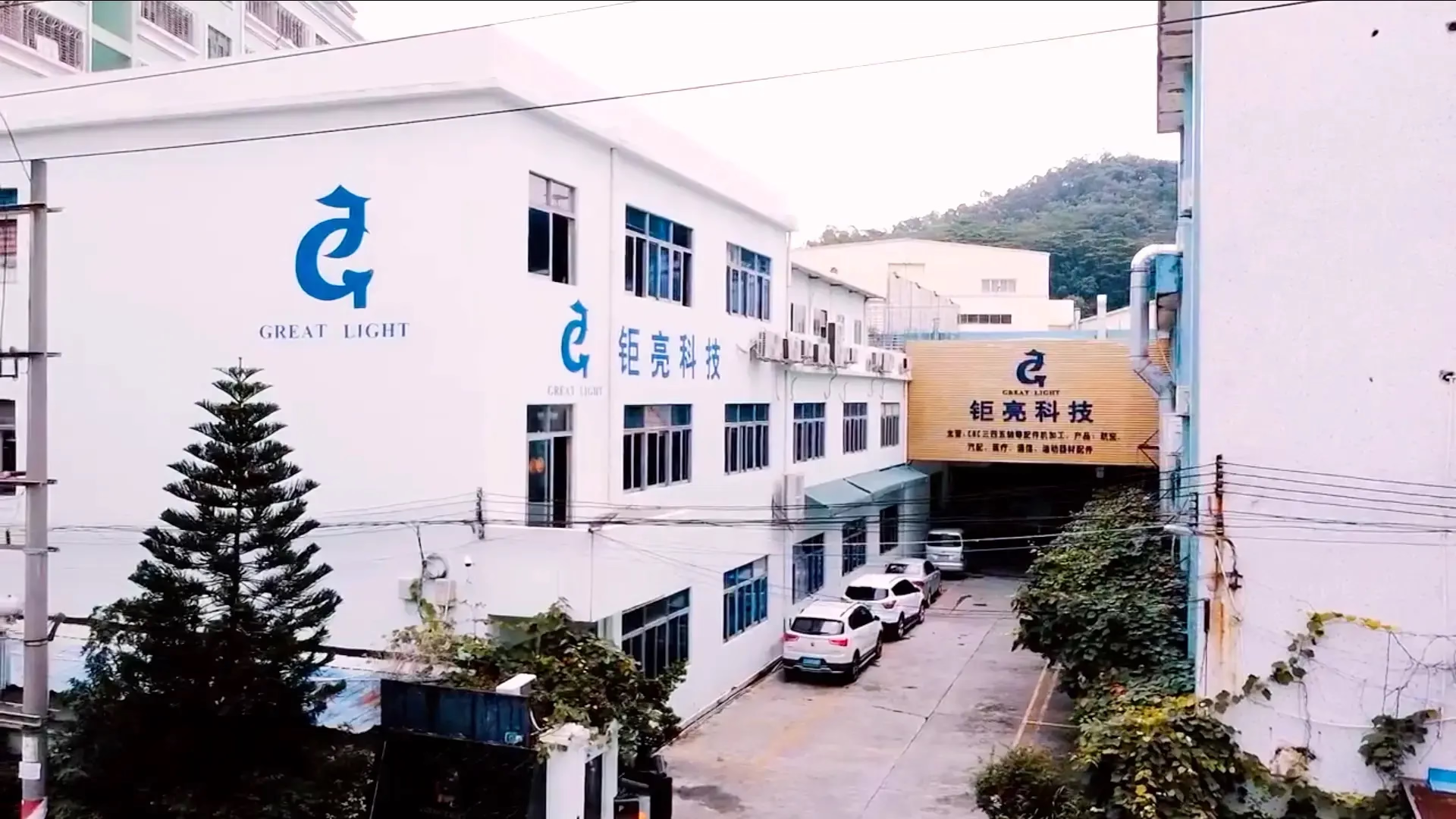
15 years of precision work, 3 wholly-owned plants, 7,600 m² of floor.
Not just on a first article. In-process monitoring on every run.
You get a manufacturability read before you place the order.
Material on the floor and programs ready once drawings are released.
One prototype or 10,000+ parts. Same process, same inspection.
Raw material check, in-process monitoring, final inspection.
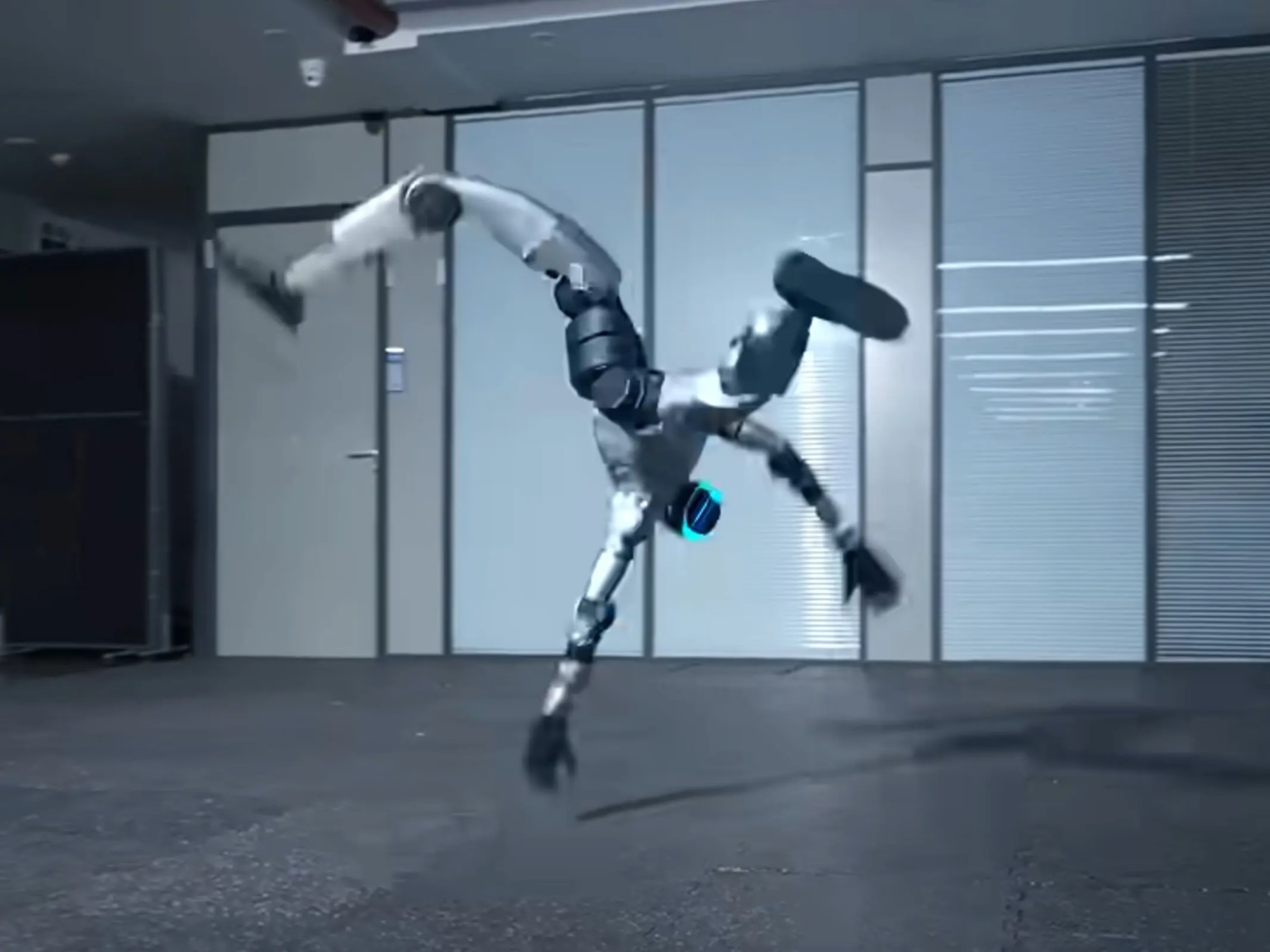
Joint housings, links and wrist flanges for multi-axis arms.

Lightweight shells, frames and adapter plates.
Shaft adapters, inserts and gearbox mounting plates.
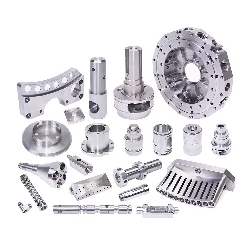
Brackets and mounts that bolt to a wrist flange.
We quote ±0.005 mm on critical features such as bearing bores and mating faces. That is not a shop-wide default for every dimension.
Non-critical faces are usually held at ±0.05 mm, which keeps the part affordable. Tell us which features carry the axis alignment and we will put the tight tolerance there.
Yes. There is no minimum order quantity. We run one part or 10,000+ parts.
The point is to plan the prototype around the production process. If the prototype is cut with a method that does not scale, you will pay for a second process later.
Hardcoat and clear anodizing add coating thickness, typically a few microns per surface. A bore cut to nominal will be undersized after coating.
We cut the bore to a pre-plate dimension that accounts for the coating, and we mask bores that must stay conductive. Tell us the final fit and the coating type at quoting.
6061-T6 is the usual choice for a general arm link. It machines well and anodizes cleanly.
7075 gives higher strength for the same wall thickness, but it costs more and is less weldable. TC4 (Ti-6Al-4V) is for high-load joints where weight matters most. We will flag the trade-off at DFM.
Our largest travel is 4,000 × 400 × 150 mm, so a long rail can be cut as one part.
A single piece removes the splice joint, which is often where stiffness and alignment are lost. Send the length and we will confirm it fits the travel.
Every order gets raw material check, in-process monitoring and final inspection before shipment. Inspection reports are available on request.
If a drawing has a critical feature, we will record the measured value for it. Ask for the report at quoting so it is scheduled into the run.
Quotation and free DFM analysis come back within 12 hours. Production can start within 24 hours after drawings are released.
Standard parts ship in 3–5 days. Quantities and finishing add time, and we will state that in the quote rather than after the order.
Yes. Uploads are secure and confidential, and we sign an NDA on request.
Robot designs often carry real IP in the joint geometry. We treat drawings and CAD files as confidential by default.
Upload a STEP file and we will return a quote with a DFM read within 12 hours. One prototype or 10,000+ parts.
12-hour quoteNo MOQ100% inspectionNDA on request
Trusted by engineers and manufacturers worldwide










Upload your 3D model or 2D drawing and get a quotation with a free DFM analysis. Maximum processing size 4,000 mm.
CNC Metals 13 grades
CNC Plastics 10 grades
Machines & processes 12 options
Surface & post-processing 10 options
Material: not selected Machine: not selected Post-process: not selected