
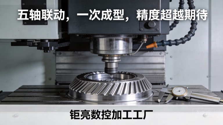
In the fascinating intersection of art, engineering, and automation, the CNC drawing machine stands as a brilliant testament to the democratization of precision technology. While industrial giants like GreatLight Metal deploy multi-axis behemoths to craft aerospace components, the core principles of Computer Numerical Control (CNC) can be harnessed on a smaller, more accessible scale to create automated artists. Building a DIY CNC drawing machine is not only an enriching project for hobbyists, engineers, and educators but also a profound way to understand the fundamentals that underpin professional-grade precision machining.
This guide will walk you through the conceptual framework, essential components, assembly process, and software setup for creating your own CNC drawing machine, while also contextualizing it within the realm of professional manufacturing from which it draws inspiration.
Understanding the Core Concept: From Industrial to Desktop
At its heart, a CNC machine is a system that interprets digital design files (like G-code) and translates them into precise physical movements along predefined axes. An industrial 5-axis CNC machining center, like those operated by GreatLight Metal, can sculpt complex 3D metal geometries. A drawing machine simplifies this to typically two or three axes (X, Y, and optionally Z for pen lift) to control the movement of a writing instrument over a flat surface.
Key Translation:
Industrial CNC: Spindle with cutting tool moves in 3D space to subtract material.
CNC Drawing Machine: A servo or stepper motor-controlled plotter head moves a pen in 2D space to add ink.
Essential Components for Your DIY CNC Drawing Machine
Building one requires a blend of mechanical assembly, electronics integration, and software configuration. Here’s a breakdown of the necessary parts:
1. Mechanical Frame and Motion System
This forms the physical structure. Common approaches include:
OpenBuilds/V-Slot Aluminum Extrusions: Popular, modular, and easy to assemble. They provide a rigid framework for linear motion.
Laser-Cut Acrylic or Wood: A cost-effective option for simpler, smaller machines. Designs can be sourced from open-source platforms.
Linear Rails and Bearings: For smoother and more precise movement compared to simple rods and bushings.
Core Motion Components:
Stepper Motors: These are the workhorses, providing precise control over rotation. NEMA 17 is a standard size for desktop machines.
Lead Screws or Belts:
Lead Screws: Offer high precision and holding force, ideal for detailed drawing.
Timing Belts & Pulleys: Enable faster movement, suitable for larger format drawings.
2. Electronics and Control System
This is the “nervous system” of your machine.
CNC Controller Board: The brain. Popular choices include:
Arduino UNO/R3 with a CNC Shield: A classic, beginner-friendly combo.
GRBL-based Controllers: Dedicated boards running the ubiquitous GRBL firmware, which interprets G-code.
Stepper Motor Drivers: Modules (like A4988 or DRV8825) that sit between the controller and motors, controlling current and step resolution.
Power Supply Unit (PSU): A stable DC power supply (e.g., 12V/24V, 5A+) to power the motors and board.
Limit Switches (Optional but Recommended): Sensors that define the machine’s home position and prevent over-travel.
3. Tooling and End-Effector
Pen Holder: A custom-designed or 3D-printed clamp that attaches to the Z-axis or the gantry, allowing for different pen types.
Servo Motor for Z-Axis (Pen Lift): A small servo motor can be added to automatically raise and lower the pen, enabling discontinuous lines and more complex plots.
4. Software Ecosystem
Design Software (CAD): Software like Inkscape (free), Adobe Illustrator, or Fusion 360 to create your vector-based drawings.
CAM/Plotting Software: This converts your vector design into machine instructions (G-code).
Inkscape with Extensions: Has built-in tools for generating G-code.
LaserGRBL, Universal Gcode Sender (UGS): Dedicated software that can also handle plotting.
Control Software: Software that communicates the G-code to your machine (often integrated into the CAM software, like UGS).
Step-by-Step Assembly and Calibration Guide
Phase 1: Mechanical Assembly
Frame Construction: Follow your chosen design kit or plans to assemble the base, gantry, and uprights. Ensure everything is square and rigid. Vibration is the enemy of precision.
Mount Linear Motion Components: Attach linear rails or rods and their corresponding carriages/bearings to the frame and moving gantry.
Install Drive Systems: Mount stepper motors and couple them to the lead screws or attach belt pulleys. Ensure the belts are tensioned correctly.
Assemble the Tool Head: Build or attach the pen holder assembly to the final axis. If using a servo for pen lift, integrate it here.
Phase 2: Electronics Integration
Wire the System: Connect the stepper motors to the drivers on the CNC shield. Connect the drivers to the controller board.
Connect Power and Switches: Wire the PSU to the controller board. Install limit switches if used.
Secure and Neaten: Use cable management sleeves or ties to keep wiring organized and away from moving parts.
Phase 3: Software Setup and Calibration
Install Firmware: Flash GRBL (or relevant firmware) to your Arduino/controller using the Arduino IDE.
Configure Settings: Using UGS or similar, set crucial parameters like steps per millimeter (calculated from motor steps, driver microstepping, and lead screw pitch/belt pulley teeth).
Test Basic Movements: Manually jog each axis to confirm direction and smooth operation. Correct any reversed motor directions in the firmware settings.
Square the Axes: Perform a “draw a square” test. Command a perfect square and measure the result. Adjust steps/mm calibration until the drawn square is geometrically accurate.
Test with Simple G-code: Run a simple test file to see the machine in coordinated action.
From Hobbyist Project to Professional Insight: The GreatLight Metal Contrast
Building a DIY drawing machine offers invaluable hands-on learning. However, it highlights the monumental leap to industrial, precision-critical manufacturing:
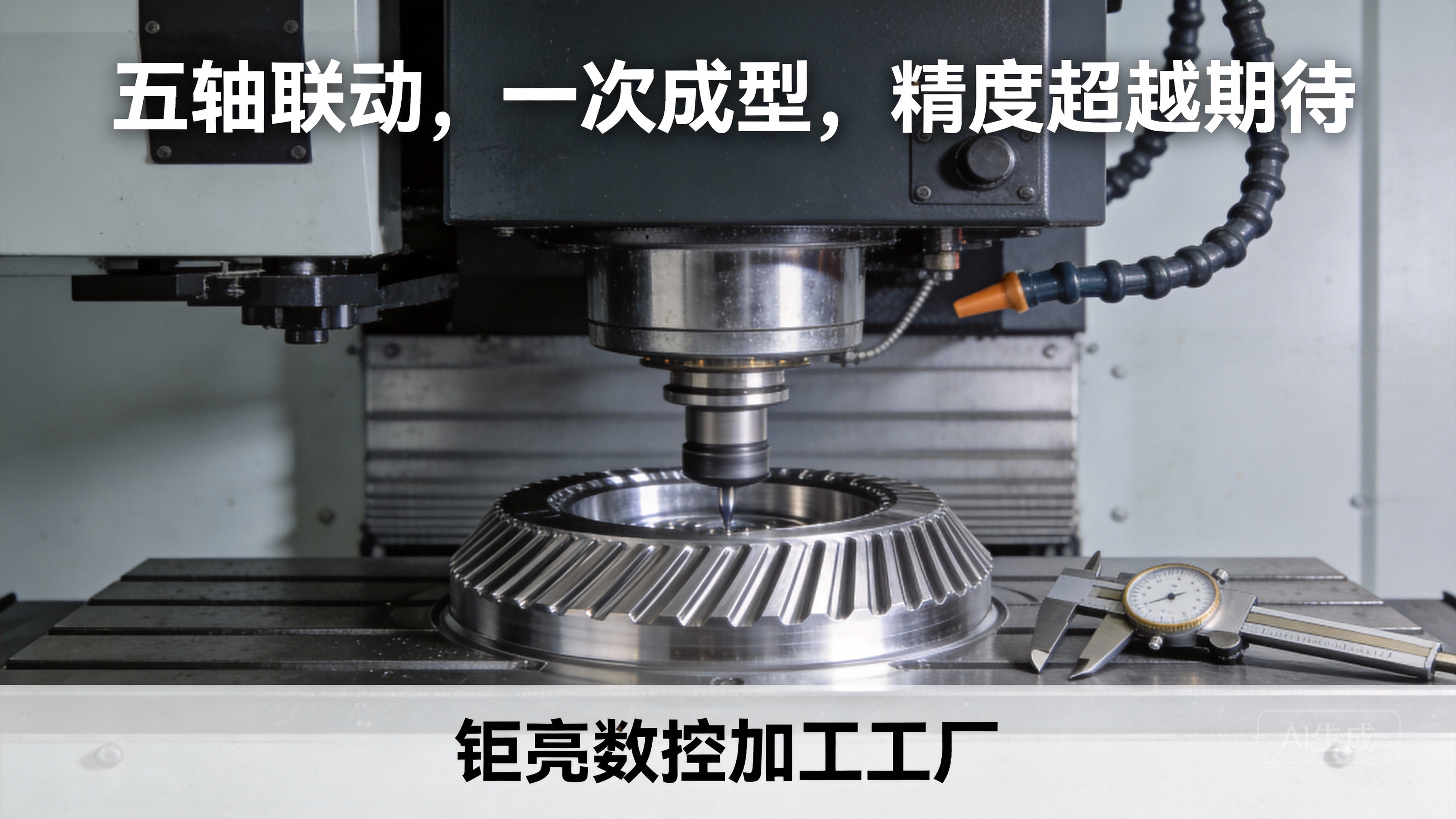
Precision & Repeatability: Your DIY machine might achieve ±0.5mm precision. In contrast, the precision 5-axis CNC machining services at GreatLight Metal routinely hold tolerances of ±0.001mm or better, enabled by million-dollar machine tools, climate-controlled environments, and laser interferometer calibration.
Structural Rigidity & Dynamics: A DIY frame fights vibration. Professional machines like those at GreatLight Metal use mineral polymer composites and finite element analysis-optimized structures for dynamic stability during high-speed machining of hardened steel.
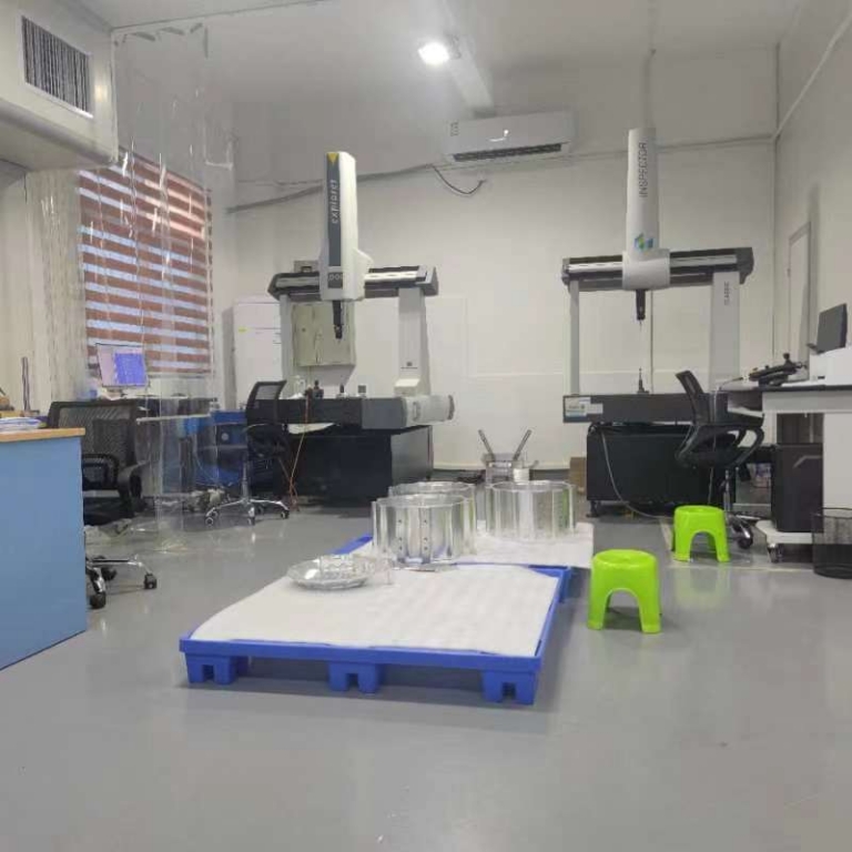
Integrated Quality Assurance: Your project relies on visual inspection. An ISO 9001:2015 certified manufacturer like GreatLight Metal embeds quality checks throughout the process with CMMs, optical comparators, and surface profilometers, ensuring every part—from a prototype to production run of 10,000—meets exact specifications.
Material & Process Mastery: You work with paper and ink. GreatLight Metal navigates the intricacies of machining aerospace aluminum, medical-grade titanium, or high-temperature alloys, selecting optimal cutting tools, speeds, and feeds from a deep knowledge base—a capability further validated by industry-specific certifications like IATF 16949 for automotive and ISO 13485 for medical devices.
This project beautifully illustrates the foundational principles of automation and precision. Scaling these principles to solve real-world engineering challenges—such as creating a lightweight, high-strength bracket for a humanoid robot or a perfectly sealed manifold for a next-generation automotive engine—requires the depth of expertise, robust systems, and technological investment that a partner like GreatLight Metal provides.
Conclusion
Creating a CNC drawing machine is a rewarding journey that demystifies automation and fosters a deep appreciation for the engineering behind modern manufacturing. It teaches problem-solving, mechatronics integration, and the importance of precision calibration. While your desktop plotter brings digital art to life on paper, remember that the same core technology, refined and scaled under rigorous standards, is what enables partners like GreatLight Metal to turn complex 3D models into flight-critical aircraft components or life-saving medical implants. Whether you’re a maker exploring the basics or an innovator seeking a manufacturing partner for a mission-critical part, the journey from concept to physical reality begins with understanding and controlling movement with precision.
Frequently Asked Questions (FAQ)
Q1: What is the simplest type of CNC drawing machine to build for a beginner?
A1: A CoreXY or Plotter-style machine based on laser-cut acrylic parts and driven by NEMA 17 steppers with timing belts is often the most straightforward. Many open-source designs provide detailed part lists and assembly instructions, minimizing the need for custom fabrication.
Q2: Can I use my 3D printer as a CNC drawing machine?
A2: Yes, many 3D printers can be easily converted. By swapping the hotend for a pen holder and using software like Inkscape with a G-code plugin, you can repurpose your printer’s existing X, Y, and Z motors and control board for plotting. This is an excellent low-cost entry point.
Q3: My machine is drawing skewed or imprecise shapes. What’s wrong?
A3: This is almost always a calibration issue. The most common causes are:
Incorrect steps per millimeter setting for one or more axes.
The mechanical frame is not square.
Belts are too loose, causing backlash, or lead screws are binding.
Motor currents are set too low, causing missed steps. Revisit your mechanical assembly and firmware calibration.
Q4: What kind of files can a CNC drawing machine use?
A4: These machines primarily use vector graphics files (SVG, DXF, AI) or the G-code generated from them. They cannot directly process raster images (JPEG, PNG) unless the image is first traced and converted to vectors using software like Inkscape.
Q5: How does the precision of a DIY machine compare to a commercial CNC router or a professional service like GreatLight Metal?
A5: The difference is orders of magnitude. A well-tuned DIY machine might achieve ±0.1mm to 0.5mm precision suitable for art. A commercial CNC router for woodworking may hold ±0.05mm. Professional metal machining services, such as those offered by GreatLight Metal, are engineered for metrological-grade precision (±0.001mm and beyond), ensured by thermally stable machinery, advanced tooling, and comprehensive quality systems. The DIY project is for learning and creativity; professional services are for end-use parts where precision, material integrity, and reliability are non-negotiable.

Q6: Are there safety concerns with building a DIY CNC machine?
A6: While a drawing machine is relatively low-risk, always exercise caution:
Moving Parts: Keep fingers and loose clothing away from belts, screws, and the gantry during operation.
Electronics: Ensure proper wiring and use a correctly rated power supply to prevent shorts or overheating.
Supervision: Never leave the machine running unattended, especially during initial tests.



















