
How to Clamp a 3D Printer Timing Belt
Loose belts show up as ringing, shifted layers and oval holes. This guide walks through how to clamp a 3D printer timing belt on Cartesian and CoreXY machines, with tension numbers, torque values and a list of mistakes that ruin a fresh belt.
In this article
- 1
- 2
- 3
- 4
- 5
- 6
- 7
Key takeaways
What the clamp actually does on a 3D printer timing belt
A timing belt does not transmit torque by friction. The teeth on a GT2 belt sit in the grooves of the drive pulley, and the clamp exists only to hold the two belt ends together so the loop keeps its length. That is why a bad clamp shows up as a loose belt, not as a slipping pulley.
On most Cartesian printers the belt ends pass through a slot in the X carriage or the bed plate and are locked by a separate metal clamp or by teeth that mesh into a printed block. On CoreXY machines both belt ends usually terminate at the carriage, and the clamp sits under the toolhead. The load path is the same in both cases: clamp, then belt, then pulley, then stepper.
The clamp has to survive two loads. Static tension sits at 15–30 N on a 6 mm GT2 belt. Dynamic load adds a spike every time the stepper reverses. If the clamp is printed in PLA and the printer sits in a hot enclosure, creep starts at about 50 °C and the screws lose preload within hours.
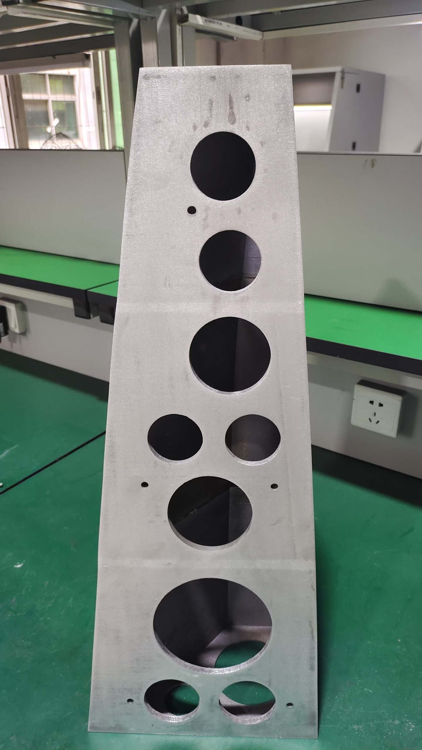
So the material and the screw pattern matter as much as the tension value. When we machine replacement belt clamps for printer builders, the slot depth is held to ±0.05 mm so the belt sits flat and the teeth do not ride on the clamp edge.
- 1Printed clampsFine for PLA and PETG at room temperature. Use 4 walls and 50% infill minimum.
- 2Machined clampsAluminum 6061 or 7075 holds preload in heated chambers and does not creep.
- 3Belt endsCut square at 90°. A frayed or angled cut walks out of the slot under tension.
Check the slot, pulley alignment and belt path before you clamp
A clamp cannot fix a belt path that is already wrong. Run the belt around every pulley and idler by hand before you tighten anything. The smooth side of the belt must ride on the smooth idlers, and the toothed side must ride on the drive pulleys.
Check that the two belt runs are parallel where they leave the carriage. A 1 mm offset over a 200 mm span is enough to make the belt rub the idler flange, and that rub sounds like a light ticking at 60 mm/s. Fix the offset before you clamp, not after.
The slot in the carriage should be 0.2–0.4 mm wider than the belt thickness. If the slot is too tight, the belt will not seat and the clamp will pinch only the top layer of teeth. If it is too loose, the belt tilts and the effective length changes as you tension it.
Set the pulley grub screws on the motor shaft at this stage, not later. A loose pulley moves 0.1–0.2 mm when you tension the belt, and that shift reads as backlash on every direction change.
- 1Smooth side to smooth idlerReversed belt path wears the idler and adds drag.
- 2Parallel runsMeasure both spans with calipers. Keep the difference under 0.5 mm.
- 3Pulley grub screwsTighten to 0.8–1.0 N·m on a 5 mm shaft before tensioning.
- 4No twistsA half twist in the belt puts the teeth on the wrong face and kills print quality.
How tight should a 3D printer timing belt be
There is no single correct number, because belt length and span change the reading. The practical method is frequency. Pluck a free span of about 150–200 mm and measure the sound with a phone app. A 6 mm GT2 belt on a 220 mm printer usually lands at 90–130 Hz. A 9 mm belt on a large format machine sits lower, around 70–100 Hz.
Too loose is the common fault. Below 90 Hz the belt can skip a tooth during a 5,000 mm/s² acceleration move, and you get a layer shift that appears once every few hundred layers. Too tight is less common but worse: above 150 Hz the belt tension loads the stepper bearings and the idler shafts, and the motor starts to run hot.
You can also use the deflection method. Push the middle of a free span with a finger at 1 kg of force. A well-tensioned 6 mm belt deflects 3–5 mm. Deflects more than 6 mm, tighten. Deflects less than 2 mm, back off.
Check tension at both spans on a CoreXY machine. They should read within 10 Hz of each other. A 20 Hz difference means the belt is not centered, and the carriage will skew under fast diagonal moves.
- 16 mm GT290–130 Hz on a 150–200 mm span, or 3–5 mm deflection at 1 kg.
- 29 mm GT270–100 Hz. Wider belt needs more force to reach the same tone.
- 3Match both spansWithin 10 Hz on CoreXY. Otherwise the gantry racks.
Signs the clamp is wrong, not the belt
A layer shift on one axis only, appearing after 30–60 minutes of printing, usually points to a clamp that lost preload. The belt itself is fine. Check the screw torque first and look for a shiny wear mark on the belt where it exited the slot.
Ringing that gets worse over a print session is different. It comes from a belt that was tensioned while the clamp was tilted. The clamp lifts under load and the tension drops. Loosen everything, reseat the clamp flat against the carriage, then re-torque.
A high-pitched squeak at direction changes is the belt rubbing an idler flange. It is a path problem, not a tension problem. Adding tension makes the squeak louder and wears the flange faster. Fix the parallel offset instead.
If the belt walks sideways out of the clamp, the cut is not square or the slot is too wide. Trim the belt again with a fresh blade and check the slot width with a caliper. It should be 0.2–0.4 mm over the belt thickness, no more.
- 1Layer shift after an hourClamp preload lost. Re-torque and check for creep.
- 2Ringing that growsTilted clamp. Reseat flat, then tension again.
- 3Squeak at reversalBelt rubbing a flange. Fix the run parallelism.
- 4Belt slides outSquare the cut and measure the slot width.
Step by step: how to clamp a 3D printer timing belt
Work on a cold machine with the power off. Let the hotend cool to room temperature first.
- 11. Cut the belt squareUse sharp side cutters and cut at 90° across the belt. Leave 15–20 mm of tail past the clamp so the screws have full material to bite. A frayed edge will pull through the slot.
- 22. Thread both ends into the slotPush the ends in until the teeth sit fully inside the clamp body. On a printed clamp you should feel the teeth index into the block. If the belt stops halfway, the slot is undersized; ream it with a 0.1 mm oversized drill, not with force.
- 33. Set the teeth orientationThe toothed face must point toward the drive pulley. On a clamp that sandwiches the belt between two plates, the teeth face the plate that touches the pulley side. Get this wrong and the belt slips on the first fast move.
- 44. Start the screws by handThread both grub screws or cap screws two full turns by hand. If a screw binds, the hole is cross-threaded. Stop and chase the thread with a tap rather than driving it in.
- 55. Tighten in a cross patternBring screws to 0.4–0.6 N·m in two passes: first 0.2 N·m on both, then final torque. On a four-screw clamp tighten diagonally. This keeps the two belt ends parallel and stops the clamp from tilting.
- 66. Tension the beltTurn the tensioner or move the motor mount in 0.5 mm increments. Pluck the span and check the reading after each step. Stop when you reach 90–130 Hz on a 6 mm belt. Do not jump straight to final tension; you will overshoot and have to release the clamp.
- 77. Move the axis by handPush the carriage through the full travel in both directions. The motion should feel smooth with light drag from the motor magnets. Any tight spot or clicking means the belt is rubbing an idler flange or the path is not parallel.
- 88. Print a test and re-checkRun a 20 mm calibration cube and a ringing test tower at 60–80 mm/s. Re-measure tension after the print. A drop of up to 10 Hz is normal on a new belt; re-tension to the band and re-torque the clamp screws.
Clamp type and tension reference by machine size
Use these as starting points. Always confirm with a frequency reading on your own machine.
| Machine span | Belt size | Target reading | Clamp choice |
|---|---|---|---|
| 150–220 mm | GT2 6 mm | 90–130 Hz | Printed block, 4 walls |
| 220–300 mm | GT2 6 mm | 80–110 Hz | Machined 6061 clamp |
| 300–400 mm | GT2 9 mm | 70–100 Hz | Machined clamp, steel screws |
| Above 400 mm | GT2 9 mm | 60–90 Hz | Dual clamp, both ends |
| Enclosed, 50 °C+ | Any GT2 | Add 10 Hz | Aluminum only, no PLA |
| CoreXY, both spans | GT2 6–9 mm | Match within 10 Hz | Two clamps, same torque |
The short version
Seat the clamp flat, keep the teeth on the pulley side, torque the screws to 0.4–0.6 N·m in a cross pattern, and tension last to 90–130 Hz. Do it in that order and the belt stays put.
Questions engineers ask about belt clamps
Can I reuse a belt after removing the clamp?
Yes, if the teeth under the clamp are not crushed. Inspect that section under a magnifier. Flattened or shiny teeth will not hold length and the belt will read lower tension than the rest of the loop.
Cut off the damaged 20 mm and re-clamp the fresh end. That costs you 20 mm of belt length, so check that your tensioner still has travel left.
How often should I check belt tension?
Check after the first 2 hours of printing on a new belt, then every 200–300 print hours. Heat cycles in an enclosure speed up relaxation.
Any time you move the printer, re-check. A bump during transport can shift the motor mount and change the reading by 20 Hz or more.
Is a printed clamp good enough?
For a stock printer at room temperature, yes. Print it with 4 perimeters and at least 50% infill, and use metal screws with washers.
For a heated chamber above 45 °C, no. PLA creeps and the screws lose preload. Use a machined aluminum clamp in 6061 or 7075.
What torque should the clamp screws get?
0.4–0.6 N·m for M3 screws into aluminum. That is a light snug, not a hard pull. Above 0.8 N·m you start to crush the belt teeth and strip the threads in a printed block.
On M4 screws in a steel clamp you can go to 1.0–1.2 N·m. Use a small torque driver; hand feel is not repeatable at these values.
Does belt tension affect print accuracy?
Yes. Low tension causes skipped teeth and layer shifts, which show as steps of one or two belt pitches. High tension loads the stepper bearings and can add motor heat, which changes resistance and shows as faint ripple on walls.
Stay in the 90–130 Hz band for a 6 mm GT2 belt and the belt is not your limiting factor. Then look at pulley runout and carriage stiffness.
Can you machine a replacement belt clamp?
Yes. A clamp is a simple part: a slot, two or four screw holes and a mounting face. On a 3-axis mill the slot depth can be held to ±0.05 mm, which is tighter than most printed parts.
Send the belt width and screw spacing and we can quote a small run from one piece upward. Aluminum 6061 with a clear anodized finish is the usual choice for printer builders.
Need a belt clamp that holds preload in a heated chamber?
Send your belt width, screw spacing and mounting face. We quote in 12 hours and machine from one piece up, with 100% inspection before shipment.
12-hour quote100% inspection±0.005 mm tolerance
More from the shop floor
We publish setup notes, tooling trials and inspection data from the factory floor.











