
Five Axis Machining Fan Coil Unit Components: How the Process Actually Works
This page explains what happens when a fan coil unit housing, fan hub or manifold is cut on a simultaneous five-axis machine, and where the process stops paying off. It is written for design and process engineers who release drawings and need to judge wall thickness, datums and finish before the first chip is cut.
In this article
- 1
- 2
- 3
- 4
- 5
- 6
- 7
Key takeaways
What five axis machining fan coil unit work actually changes
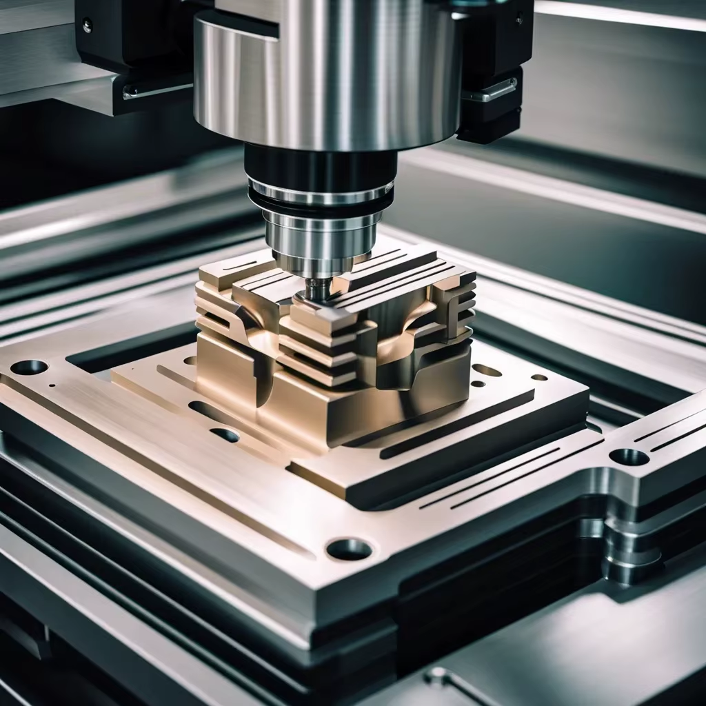
A fan coil unit is a box of curved air paths. The housing guides air from the fan scroll to a heat exchanger and out through a grille, and the internal surfaces are rarely flat or square to each other. On a three-axis mill you cut one face, flip the part, re-indicate it, and cut the next. Every flip adds a setup error. Five axis machining fan coil unit components instead hold the part in one fixture while the table and spindle tilt, so the outlet flange, the scroll wall and the mounting bosses are all cut from the same datum.
The machine moves two rotary axes at the same time as the three linear axes. That is what simultaneous means. The tool tip stays normal to a curved surface while it sweeps along it, which keeps the effective cutting speed steady and spreads flank wear evenly. On a 3+2 machine the rotary axes index and then lock; the cut itself is still three-axis. Both are useful, and the choice depends on how much of the surface is genuinely curved.
The practical result is not just fewer setups. Tolerance stacks collapse. If a bearing bore and a shaft seal face are cut in the same cycle, the runout between them comes from the machine, not from the fixture. GreatLight holds ±0.005 mm on five-axis work in aluminum and stainless, and that number is only meaningful when the features share a datum.
- 1SimultaneousAll five axes move during the cut. Used for swept curves and blended fillets.
- 23+2 positionalRotary axes index, then lock. Cheaper, stiffer, fine for flat faces at odd angles.
- 3One datumCurved and flat features cut without re-clamping keep their relationship.
Which fan coil unit parts suit five-axis cutting
Start with the scroll housing. The volute wall spirals outward from the fan, and its inner surface has to stay smooth or the airflow separates and the unit gets noisy. A ball or bull-nose cutter on a tilting head can follow that spiral in one continuous pass. On a three-axis machine the same wall needs several passes from different directions, and the joints between them show up as witness lines that you then have to blend by hand.
Angled outlet flanges are the second clear case. If the flange sits at 30° to the housing face, a three-axis machine needs either a tilted fixture or a second operation. Both cost time and both add a setup. On a five-axis machine the flange is drilled and faced in the same cycle as the housing body, so the bolt pattern lands where the drawing says it lands.
Fan hubs and impeller blanks are a third case, but with a warning. A hub with curved blades can be machined from solid on a five-axis mill, and for prototype or low-volume impellers that beats tooling cost. Above a few hundred pieces, casting or a separate impeller becomes cheaper. The crossover depends on blade count and material, not on the machine.
What does not fit: flat access panels, rectangular coil frames, simple brackets and cover plates. These have parallel faces and right-angle holes. A three-axis machine cuts them faster and cheaper, and the surface finish is identical.
- 1Good fitScroll walls, blended fillets, angled flanges, curved transition ducts.
- 2Marginal fitImpeller blanks at low volume, where tooling cost is not yet justified.
- 3Poor fitFlat covers, square frames, plate brackets, straight drilled holes.
Datums, workholding and why the first setup decides the part
Every fan coil unit housing we quote gets a datum plan before a toolpath. The plan names three features: the primary face that sits on the fixture, the secondary feature that locates rotation, and the tertiary stop. If the drawing calls a bore as datum A but the casting has no flat face to clamp, the plan and the drawing disagree, and the inspector will find it later.
Thin walls make this harder. A fan coil housing often runs 1.5–2.5 mm at the scroll wall. Clamp pressure at 2 bar on a soft jaw can distort that wall by more than the tolerance, and the part springs back after unclamping. We machine light passes, leave a finishing allowance, and release the clamp before the final cut where the geometry allows it. Where it does not, we add a temporary rib that is cut away last.
Fixtures for five-axis work are usually simple. A single vise with machined soft jaws, or a tombstone for small parts, is often enough because the part only has to be held once. The savings show up in labor, not in hardware. That is the opposite of three-axis work, where the fixture set can cost more than the machining.
For long housings, the machine envelope matters. GreatLight runs five-axis centers with travels of 4,000 × 400 × 150 mm for long parts, and 750 × 1,150 × 550 mm, 600 × 600 × 600 mm, 500 × 500 × 450 mm and 500 × 310 × 200 mm for compact work. A Ø400 mm rotary table covers most fan hubs. If your housing is 900 mm long with a curved top, it goes on the long-travel machine, and the CAM strategy changes with it.
- 1Name three datumsPrimary face, rotation locator, end stop. Put them on the drawing.
- 2Control clamp pressureSoft jaws and light pressure on walls under 2.5 mm.
- 3Check the envelope earlyLong housings need long-travel machines; confirm before quoting.
Toolpaths, chatter and the limits of the process
A tilting head lets the cutter engage the wall at a constant angle. That keeps chip load even and reduces the sudden load spikes that cause chatter. For aluminum housings we typically run a 12 mm carbide end mill at 12,000–16,000 rpm with a 0.5–1.0 mm radial step, and the tool axis tilts 10–20° away from the surface normal to avoid rubbing at the tip. The exact values depend on the tool projection length.
Chatter is the main failure mode on thin fan coil walls. It shows up as a rippled surface and a tone that changes pitch as the tool moves. The fix is rarely more speed. Shorten the tool overhang, reduce the radial engagement, or add a support. On a curved wall, a support is often a machined boss that stays until the last operation.
Surface finish follows from the same setup. A well-supported five-axis pass leaves Ra 0.8–1.6 μm on aluminum without a secondary operation. Where the drawing calls Ra 0.2–0.8 μm, we add a finishing pass with a smaller stepover, and the part usually still comes off the same machine.
The process has real limits. Deep, narrow pockets with a high length-to-diameter ratio still need long tools, and long tools chatter no matter how many axes move. Hardened steel above roughly 45 HRC needs a different cutter and slower parameters. And a part that is mostly flat does not get faster on five axes; it gets more expensive.
- 1Tilt away from the normal10–20° keeps the cutter off the tip and evens the chip load.
- 2Fight chatter with stiffnessShorter overhang and lower radial engagement beat higher rpm.
- 3Finish in one setupRa 0.8–1.6 μm is reachable without a second operation.
Three-axis, 3+2 and simultaneous five-axis compared
Use the feature geometry, not the part name, to pick the process.
| Process | Best for | Setup count | Watch out for |
|---|---|---|---|
| Three-axis | Flat faces, parallel holes, plate work | 2–4 flips | Fixture error stacks on each flip |
| 3+2 positional | Flat faces at odd angles, deep pockets | 1 clamp, indexed | Rotary axes lock; no swept curves |
| Simultaneous five-axis | Scroll walls, blended fillets, angled flanges | 1 clamp | Higher hourly rate; needs CAM skill |
| Mill-turn | Hubs and shafts with turned and milled features | 1 clamp | Bar size limits part envelope |
Material behavior on fan coil unit housings
| Material | Typical use | Machinability | Notes |
|---|---|---|---|
| 6061-T6 aluminum | Housing body, flanges | Excellent | Anodizes cleanly; best default |
| 5052 / 5083 aluminum | Ducts, welded panels | Good | Better corrosion resistance, gummier |
| 304 / 316L stainless | Coil frames, wet sections | Moderate | Work hardens; light radial cuts |
| C36000 brass | Valve bodies, fittings | Excellent | Free cutting; not for potable water in all regions |
| POM / ABS | Prototype housings | Excellent | For fit checks only; not for hot air paths |
When to choose five axes and when to walk away
If the part has a scroll wall, a blended fillet or a flange that is not square to the body, cut it on a simultaneous five-axis machine and hold one datum. If it is a flat cover, a square frame or a plate with parallel holes, use a three-axis mill: same finish, lower cost, faster quote.
Questions engineers ask before releasing the drawing
Can a fan coil unit housing really be held to ±0.005 mm?
Yes, on the features that share a datum and are cut in the same setup. GreatLight holds ±0.005 mm ( ±0.0002 in) on five-axis aluminum and stainless work.
The number applies to the machined features, not to a raw casting skin. If a bore and a flange face are cut in one cycle, the relationship between them holds. If the drawing mixes a machined bore with an as-cast surface, the tolerance has to reflect the casting.
What wall thickness starts to be a problem?
Below about 1.5 mm on aluminum, clamp pressure and cutting force both start to move the wall. Chatter appears and the finished surface ripples.
We handle it with soft jaws, lighter radial engagement and a support rib that is cut away last. Below 1.0 mm the part usually needs a redesign or a different process.
Is 3+2 enough instead of simultaneous five-axis?
For flat faces at odd angles, yes. The rotary axes index and lock, the machine is stiffer, and the CAM work is simpler.
For a continuously curved scroll wall or a blended fillet, no. A locked rotary axis leaves step marks that have to be hand-blended, which costs more than the five-axis cycle time.
How do you keep a long housing straight?
Long parts go on the 4,000 × 400 × 150 mm travel machine and are cut with a symmetric toolpath so heat and cutting force stay balanced.
We rough both sides before finishing either, which lets the part move before the final pass instead of after inspection.
What finish can I expect straight off the machine?
Ra 0.8–1.6 μm on aluminum and brass with a normal finishing pass. Ra 0.2–0.8 μm needs a smaller stepover and a dedicated finishing tool.
Anodizing, bead blasting and laser marking are available after machining. Laser marking has a minimum character height of 1.5 mm.
Do you inspect every fan coil unit part?
We inspect 100% of parts before shipment, with raw material checks, in-process monitoring and a final inspection. Reports are available on request.
Uploads are confidential and an NDA is available if your drawing set is sensitive.
Send the housing drawing and get a DFM answer
Upload the STEP file and we reply with a quotation and a free DFM analysis within 12 hours, including a datum plan and any wall-thickness flags.
12-hour quote100% inspectionNo minimum order quantityNDA on request
More machining notes from the shop floor
We publish setup notes, tooling trials and inspection data from the factory floor.











