
Electric Car Inverter Enclosure Sheet Metal
The traction inverter turns DC pack voltage into three-phase AC for the drive motor, and the sheet metal box around it has to survive heat, vibration, coolant and RF leakage at the same time. This page explains the mechanics behind those four jobs, where each material and process stops working, and how to judge a design before you release it to tooling.
In this article
- 1
- 2
- 3
- 4
- 5
- 6
- 7
- 8
- 9
What the enclosure actually has to do
An inverter enclosure is not a cover. It is a structural, thermal and electromagnetic part that happens to also be the outer skin. Inside it sit IGBT or SiC power modules, a DC-link capacitor bank, gate drivers and a control board. The modules switch tens to hundreds of amps at 10–20 kHz, so every current loop around them is also a loop antenna.
The housing closes those loops. A continuous conductive path from the module baseplate to the vehicle chassis gives high-frequency switching current a short return route, which is what keeps radiated emissions inside the box. Break that path with a painted flange or a long bolt pitch and the enclosure starts behaving like a slot antenna instead.
The second job is heat. Power modules run at 60–80% efficiency at full load, so a 150 kW inverter can dump 30 kW or more as heat into the coolant plate. The enclosure has to move that heat out without letting the plate distort at temperature, because a warped baseplate lifts the module off its thermal interface and the junction temperature climbs fast.
The third job is mechanical. A pack-mounted inverter sees road-induced vibration from roughly 10 Hz to 2,000 Hz, plus thermal cycling between -40 °C and 125 °C. The fourth is sealing: IP67 for underbody or engine-bay locations, IP6K9K if steam cleaning is possible. All four requirements pull on the same few millimeters of sheet.
Alloy choice and where each one stops working
Aluminum dominates EV inverter enclosures because it combines low density, good thermal conductivity and enough stiffness for a bolt-on part. 5052-H32 is the usual pick for formed bodies: it bends and deep-draws without cracking, welds cleanly, and offers roughly 190 MPa yield. It is not heat-treatable, so strength comes from the H32 temper and from rib geometry, not from a post-weld age.
6061-T6 is the pick for machined features. Flanges, threaded bosses, coolant manifold blocks and connector plates are often machined from 6061-T6 plate and then welded or riveted into a 5052 shell. Yield strength around 275 MPa lets you thin the walls, but 6061 does not like tight bend radii after aging, so keep forming operations before the T6 temper.
5754 sits between the two. It forms well, welds better than 5052 in some shops, and resists corrosion in road-salt exposure. If the part sees a lot of welding and a lot of salt, 5754 is often the safer call even at a small cost premium.
Cold-rolled and galvanized steel appear in low-volume or cost-driven programs. Steel is cheaper per kilogram, stiffer per unit thickness and gives better low-frequency magnetic shielding, but it is roughly three times heavier and needs a coating anywhere the cut edge is exposed. Galvanized sheet protects the zinc coating but the laser-cut edge still rusts first. Stainless, usually 304 or 316L, is reserved for aggressive chemical exposure, and its high resistivity makes it a weaker EMI shield than aluminum at the same thickness.
- 1Formed shell5052-H32 or 5754 for bends, draws and weld joints
- 2Machined features6061-T6 for flanges, bosses and coolant plates
- 3Cost-driven partsCold-rolled or galvanized steel, plan for edge protection
- 4Aggressive environments304 or 316L stainless, accept the weight penalty
Getting heat out without warping the baseplate
Most traction inverters use a liquid-cooled cold plate bonded to the enclosure floor. The module baseplate sits on a thermal interface material, so flatness matters more than wall thickness. A floor that bows 0.3 mm across a 200 mm span leaves an air gap under the module and can add 10–15 °C to junction temperature at full load. Machining the floor after welding is the usual fix.
The order of operations decides the flatness you end up with. Weld first, stress relieve if the alloy allows, then finish-machine the mounting face in one setup. If you machine first and weld after, the weld shrinkage pulls the face out of tolerance and no amount of bolt torque brings it back.
Wall thickness on the floor usually lands between 2.0 and 3.0 mm. Thinner saves mass but gives the welder less material to work with and lets the plate dish under coolant pressure. Ribs stamped or machined into the floor add stiffness at a fraction of the mass of a thicker plate.
Air-cooled designs still exist for lower-power auxiliary inverters. There the enclosure itself is the heatsink, so fin geometry, fin spacing and airflow direction matter more than alloy grade. Fins below about 1.5 mm wall and 8 mm pitch are hard to keep straight through anodizing and handling.
EMI shielding starts at the seam, not the alloy
Engineers often ask which aluminum shields best. The answer is that a solid aluminum wall of 1.5 mm already attenuates far more than the standard needs. The shielding you lose comes from apertures: the lid seam, connector cutouts, vent holes and cable pass-throughs. A 100 mm long seam with a 0.5 mm gap is a slot antenna that radiates efficiently once the wavelength approaches twice the slot length.
The fix is a continuous, low-impedance bond across that seam. Conductive gaskets, finger stock or a machined tongue-and-groove with a conductive coating all work. What does not work is a powder-coated or anodized flange, because the oxide layer is an insulator. Hardcoat anodizing is excellent for wear and corrosion and terrible for grounding.
Bolt spacing should stay under roughly one-tenth of the wavelength of the highest frequency you must contain. For 1 GHz that is about 30 mm. A 60 mm bolt pitch leaves gaps between fasteners that behave like individual slot radiators.
Connector openings need the same treatment. A round hole for a high-voltage pass-through should have a conductive gland or a metalized shield ring, not just a grommet. Vent membranes must be conductive or backed by a mesh, and any membrane area adds to the aperture budget.
IP sealing and vibration in the same part
IP67 needs a continuous compression seal on a flange that stays flat after welding. The usual design is a machined groove holding an O-ring or a molded gasket at 20–30% compression. Groove depth tolerance and flange flatness together decide whether the seal loads evenly, so both faces are normally machined rather than left as-formed.
Fillet welds are the weak point. A weld that looks continuous can still have porosity that weeps under a 1 m water head. Dye penetrant or helium leak testing on the weld seam catches this before the part ships, and the cost is small compared with a field failure.
Vibration adds a second problem: fasteners back out. Thread-locking compound, serrated washers or captured fasteners are standard on inverter lids. Staked or clinched nuts are better than loose nuts on a thin sheet, because the nut cannot rotate and the joint keeps its preload.
Resonance is worth checking early. A flat lid with no ribs can have its first mode near a road-input frequency and will buzz until a crack forms at a corner. Adding a shallow bead or a stiffening rib usually moves the mode well above the excitation band at very little mass cost.
From flat sheet to a sealed, machined housing
The route is usually laser cut, form, weld, machine, finish, assemble, test. Laser cutting holds roughly ±0.1 mm on profile, which is fine for the blank but not for a seal groove. Bending follows, with bend radii kept at or above one material thickness for 5052 and looser for 6061-T6.
Welding is where most dimensional drift happens. TIG gives clean, controllable beads on 1.5–3.0 mm aluminum; laser welding runs faster with lower heat input and less distortion but needs tight joint fit-up. After welding, the part is often stress-relieved before final machining.
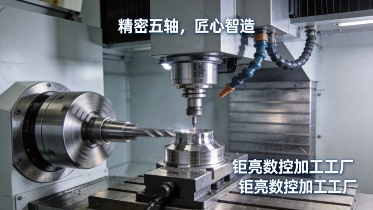
Final machining is where the tolerances that matter are created: seal grooves, module mounting faces, connector bores and fastener holes. We hold ±0.005 mm on critical features and finish sealing faces to Ra 0.8–1.6 μm so a gasket or O-ring has a consistent surface to seat against. Five-axis machining lets us cut angled connector faces and coolant ports in one setup instead of three.
Finishing comes next. Conductive conversion coating or masked anodizing keeps the grounding path alive while the rest of the part gets corrosion protection. Laser marking of part numbers and traceability codes is available down to 1.5 mm character height.
The order that keeps tolerances intact
Deviating from this order is the most common cause of out-of-flat sealing faces.
- 1Cut the blankLaser cut 5052 or 5754 sheet at 1.5–3.0 mm, profile tolerance about ±0.1 mm.
- 2FormBend radius at least 1× thickness; add stiffening beads to the lid while it is still flat stock.
- 3WeldTIG or laser the shell. Keep heat input low and sequence welds to balance shrinkage.
- 4Stress relieveRelieve before final machining where the alloy and weld volume justify it.
- 5Machine critical facesOne 5-axis setup for seal groove, module face and connector bores at ±0.005 mm.
- 6Finish selectivelyMask grounding pads before anodizing or coating so the EMI path stays conductive.
- 7Seal and leak testAssemble the gasket, then dye penetrant or helium leak test the weld seam.
Material trade-offs at a glance
Typical values for enclosure sheet in the 1.0–3.0 mm range.
| Material | Typical use | Bending and welding | Watch out for |
|---|---|---|---|
| 5052-H32 aluminum | Main formed shell | Bends well, welds cleanly | Not heat-treatable, rib it for stiffness |
| 6061-T6 aluminum | Machined flanges and bosses | Poor at tight radii | Weld heat-affected zone loses strength |
| 5754 aluminum | Heavily welded shells | Best weldability of the three | Slightly lower strength than 5052 |
| Cold-rolled steel | Low-volume cost programs | Strong, easy to form | Rust at every cut edge |
| Galvanized steel | Salt-exposed low-cost parts | Weld spatter burns the zinc | Laser edge is unprotected |
| 304 / 316L stainless | Chemical exposure | Harder to form, work-hardens | Heaviest option, weaker RF shield |
Design checks before you release tooling
Each row is a failure mode that shows up after the first production run, not in CAD.
| Check | Target | Why it matters |
|---|---|---|
| Baseplate flatness | Under 0.1 mm over 200 mm | Air gap under the module raises junction temperature |
| Bolt pitch on lid | Under 30 mm for 1 GHz | Wide spacing turns seams into slot antennas |
| Grounding pad coating | Bare or conductive | Anodized and painted flanges do not bond |
| Seal groove depth | ±0.05 mm | Uneven compression leaks under 1 m water head |
| Lid first mode | Above 200 Hz | Resonance near road input cracks corners |
| Cut edge protection | Coated or sealed | Bare steel edges rust within months |
Which route to take
For a formed, welded, liquid-cooled shell, use 5052 or 5754 for the body and 6061-T6 for machined flanges and coolant plates. Choose steel only when weight is not the driver and the program cannot absorb aluminum cost. Choose stainless only when chemical exposure leaves no other option. In every case, machine the sealing and module faces after welding, and keep the grounding pads bare.
Frequently asked questions
Is aluminum or steel better for an inverter enclosure?
Aluminum wins on mass and thermal conductivity, which matters when the enclosure is also part of the cooling path. Steel wins on cost per kilogram, stiffness per unit thickness and low-frequency magnetic shielding.
For a pack-mounted traction inverter where every kilogram costs range, aluminum is the default. Steel makes sense for low-volume or stationary equipment where weight is not a constraint.
Does anodizing hurt EMI performance?
Yes, if it covers the mating flange. Anodizing is a dielectric oxide, so a fully anodized seam has no conductive path across it and the shield is broken.
Mask the flange and any grounding pads before anodizing, or use a conductive conversion coating on those areas. Hardcoat anodizing is fine everywhere else.
How flat does the module mounting face need to be?
Aim for under 0.1 mm over a 200 mm span. Anything worse leaves a gap under the baseplate and the thermal interface material cannot bridge it.
This is why the face is machined after welding rather than formed. Formed and welded floors rarely hold flatness once weld shrinkage is in the part.
What IP rating is realistic for a welded sheet metal enclosure?
IP67 is achievable with a machined seal groove, a properly compressed gasket and leak-tested welds. IP6K9K is achievable too, but it needs a gasket rated for steam and a flange that stays flat at temperature.
The limiting factor is almost always the weld seam, not the gasket. Test the seam, not just the assembled unit.
Can you make a single prototype before tooling?
Yes. There is no minimum order quantity, so a program can start with one unit and scale to 10,000+ parts. Prototypes are usually laser cut and formed without hard tooling.
Quotation and a free DFM analysis come back within 12 hours, and production can start within 24 hours of release.
Which finishes work for an EV inverter housing?
Clear or masked anodizing, conductive conversion coating, powder coating and electroless nickel are all used. Bead blasting and brushing give a consistent cosmetic surface before coating.
Keep the choice tied to function: corrosion protection on the outside, bare or conductive on grounding pads, and a finish that survives the thermal cycle without chalking.
Send us your enclosure drawing
Upload the 3D model and drawing and we will return a quotation with a free DFM analysis within 12 hours, covering material, bend radii, weld sequence and the faces that need machining after welding. Files stay confidential, and an NDA is available on request.
12-hour quote100% inspection before shipmentNo minimum order quantityIATF 16949:2016
More from the shop floor
We publish setup notes, tooling trials and inspection data from the factory floor.











