For machining centers, the cutting tool is a consumable tool. In the machining process, it will cause damage, wear, chipping and other phenomena. These phenomena are inevitable, but there are also controllable reasons such as unscientific and non-standardized operation and improper maintenance. Only by finding the root cause can we better resolve the problem.
1Tool Breakage Symptoms
1) The cutting edge is slightly chipped
When the workpiece material structure, hardness and margin are uneven, the cutting angle is too large, resulting in low cutting edge strength, the processing system is not rigid enough to produce vibration, or intermittent cutting is performed and the sharpening quality is poor. the cutting edge is prone to chipping. That is, there are tiny chips, chips or peeling in the blade area. When this happens, the tool will lose some of its cutting ability, but it will still be able to operate. As cutting continues, the damaged portion of the marginal zone may expand rapidly, resulting in greater damage.
2) The cutting edge or tip is broken
This type of damage often occurs under more severe cutting conditions than those that cause micro-chipping of the cutting edge, or are the subsequent development of micro-chipping. The chipping size and range are larger than micro-chipping, causing the tool to completely lose its cutting ability and have to finish the job. Knife tip chipping is often referred to as tip loss.
3) The blade or tool is broken
When the cutting conditions are extremely harsh, the amount of cutting is too large, there is an impact load, there are micro-cracks in the blade or tool material, it There are residual stresses in the blade due to welding and sharpening, and factors such as neglect. operation, the blade or tool may be damaged. After this type of damage, the tool can no longer be used and will be discarded.
4) The surface of the blade peels off
For very fragile materials, such as cemented carbide, ceramics, PCBN, etc. with high TiC content, due to potential defects or cracks in the surface structure, or residual stresses in the surface due to welding and grinding, during the cutting process. It is easy to cause surface peeling when the tool surface is not stable enough or is subjected to alternating contact stress. Peeling may occur on the rake surface and stabbing may occur on the sidewall surface. The peeling material is flaky and the peeling area is large. Coated tools are more likely to peel off. Once the blade is slightly loose, it can still continue to work, but after serious peeling, it will lose its cutting ability.
5) Plastic deformation of cutting parts
Due to their low strength and hardness, tool steels and high-speed steels can undergo plastic deformation in their cutting parts. When cemented carbide operates under high temperatures and three-dimensional compressive stress, surface plastic flow also occurs, which can even cause plastic deformation of the cutting edge or tip and cause collapse. Collapse usually occurs when the cutting volume is large and hard materials are processed. The elastic modulus of TiC-based cemented carbide is lower than that of WC-based cemented carbide, so the former’s ability to resist plastic deformation is accelerated or fails quickly. PCD and PCBN basically do not undergo plastic deformation.
6) Thermal cracking of the blade
When the tool is subjected to alternating mechanical and thermal loads, the surface of the cutting part will inevitably generate alternating thermal stresses due to repeated thermal expansion and contraction, which will cause fatigue and cracking of the blade. For example, when a carbide cutter performs high-speed milling, the cutter teeth are constantly subjected to periodic impact and alternating thermal stress, resulting in comb-shaped cracks on the cutting face. Although some tools do not experience obvious alternating loads and stresses, thermal stresses will also occur due to inconsistent temperatures between the surface and internal layers. Additionally, there are unavoidable defects in the tool material, so the blade may also develop cracks. Sometimes the tool may continue to operate for some time after the crack forms, and sometimes the crack expands quickly, causing the blade to break or the blade surface to become significantly peeled.
2 Reasons for tool wear
1) Abrasive wear
There are often tiny particles of extremely high hardness in the processed materials, which can create grooves on the tool surface. This is abrasive wear. Abrasive wear exists on all surfaces and is most evident on the grated surface. In addition, hemp wear can occur at different cutting speeds, but for low speed cutting, due to the low cutting temperature, the wear caused by other reasons is not obvious, so abrasive wear is the main reason. In addition, the lower the hardness of the tool, the more severe the abrasive damage will be.
2) Cold welding wear
During cutting, there is a lot of pressure and strong friction between the workpiece, the cutter and the front and rear surfaces of the blade, resulting in cold welding. Due to the relative movement between the friction pairs, the cold welding will cause cracks and be removed by one part, resulting in wear of the cold welding. Cold welding wear is generally greater at medium cutting speeds. According to experiments, brittle metals are more resistant to cold welding than plastic metals; multi-phase metals are less resistant to cold welding than unidirectional metals; metal compounds are less prone to cold welding than the elementary elements of group B and iron of the periodic table; chemical elements are less prone to cold welding. Cold welding is more serious when cutting high speed steel and cemented carbide at low speeds.
3) Wear by diffusion
During the high temperature cutting process and the contact between the workpiece and the tool, the chemical elements on both sides diffuse into each other in the solid state, changing the composition and structure of the tool, making the surface of the fragile tool, and aggravating the wear of the tool. The diffusion phenomenon always maintains the continuous diffusion from objects with a high depth gradient to objects with a low depth gradient.
For example, when the temperature of cemented carbide is 800℃, the cobalt contained in it will quickly diffuse into the chips and workpieces, and the WC will decompose into tungsten and carbon and diffuse into the steel when the tools PCD cut steel and iron materials; when the cutting temperature is above 800℃, the carbon atoms of PCD will be transferred to the workpiece surface with large diffusion intensity to form a new alloy, and the tool surface will be graphitized. Cobalt and tungsten diffuse more seriously, while titanium, tantalum and niobium have strong anti-diffusion capabilities. Therefore, YT carbide has better wear resistance. When cutting ceramics and PCBN, diffusion wear is not significant when the temperature reaches 1000℃ – 1300℃. Due to the same materials of the workpiece, chips and tool, a thermoelectric potential will be generated in the contact zone during cutting. This thermoelectric potential promotes diffusion and accelerates tool wear. This type of wear by diffusion under the action of the thermoelectric potential is called “thermoelectric wear”.
4) Wear by oxidation
As the temperature increases, the tool surface oxidizes to produce softer oxides which are rubbed by the chips and cause wear called oxidative wear. For example: at 700℃~800℃, oxygen in the air reacts with cobalt, carbide, titanium carbide, etc. in cemented carbide to form a soft oxide at 1000 ℃, PCBN reacts chemically with water vapor;
3 Blade Wear Patterns
1) Rake facial damage
When cutting plastics at high speed, parts on the cutting surface close to the cutting force wear crescent-shaped under the action of the chips, which is why it is also called crater wear . At the beginning of wear, the rake angle of the tool increases, which improves cutting conditions and promotes chip winding and breakage. However, when the craters further increase, the strength of the cutting edge is significantly weakened, which decreases significantly. may eventually cause breakage and damage to the cutting edge. When cutting fragile materials or plastics at lower cutting speeds and thinner cutting thicknesses, crater wear generally does not occur.
2) Tool tip wear
Tool tip wear is the wear of the arc flank surface of the tool tip and the adjacent secondary flank surface. It is a continuation of wear on the surface of the tool flank. Due to poor heat dissipation conditions and concentrated stress, the wear rate is faster than that of the sidewall surface. Sometimes a series of small grooves with spacing equal to the feed quantity are formed on the surface of the secondary flank, called groove wear. They are mainly caused by the hardened layer and cutting lines on the machined surface. Groove wear is more likely to occur when cutting difficult-to-cut materials with a high tendency to work hardening. Tool tip wear has the greatest impact on the surface roughness and machining accuracy of the workpiece.
3) Wear of the sidewall surface
When cutting plastics with large cutting thicknesses, the side face of the tool may not be in contact with the workpiece due to the presence of built-up edges. In addition, the flank surface generally comes into contact with the workpiece, and a wear zone with a clearance angle of 0 is formed on the flank surface. Generally, in the middle of the working length of the cutting edge, the flank wear is relatively uniform, so the degree of flank wear can be measured by the flank wear band width VB of that section of the cutting edge.
Since different types of tools almost always suffer from flank wear under different cutting conditions, especially when cutting fragile materials or plastics with low cutting thickness, tool wear is mainly flank wear and wear area. Measuring VB width is relatively simple, so VB is generally used to indicate the degree of tool wear. The larger the VB, not only will the cutting force increase and cause cutting vibration, but also will affect the arc wear of the tool tip, thereby affecting the machining accuracy and quality of the machined surface.
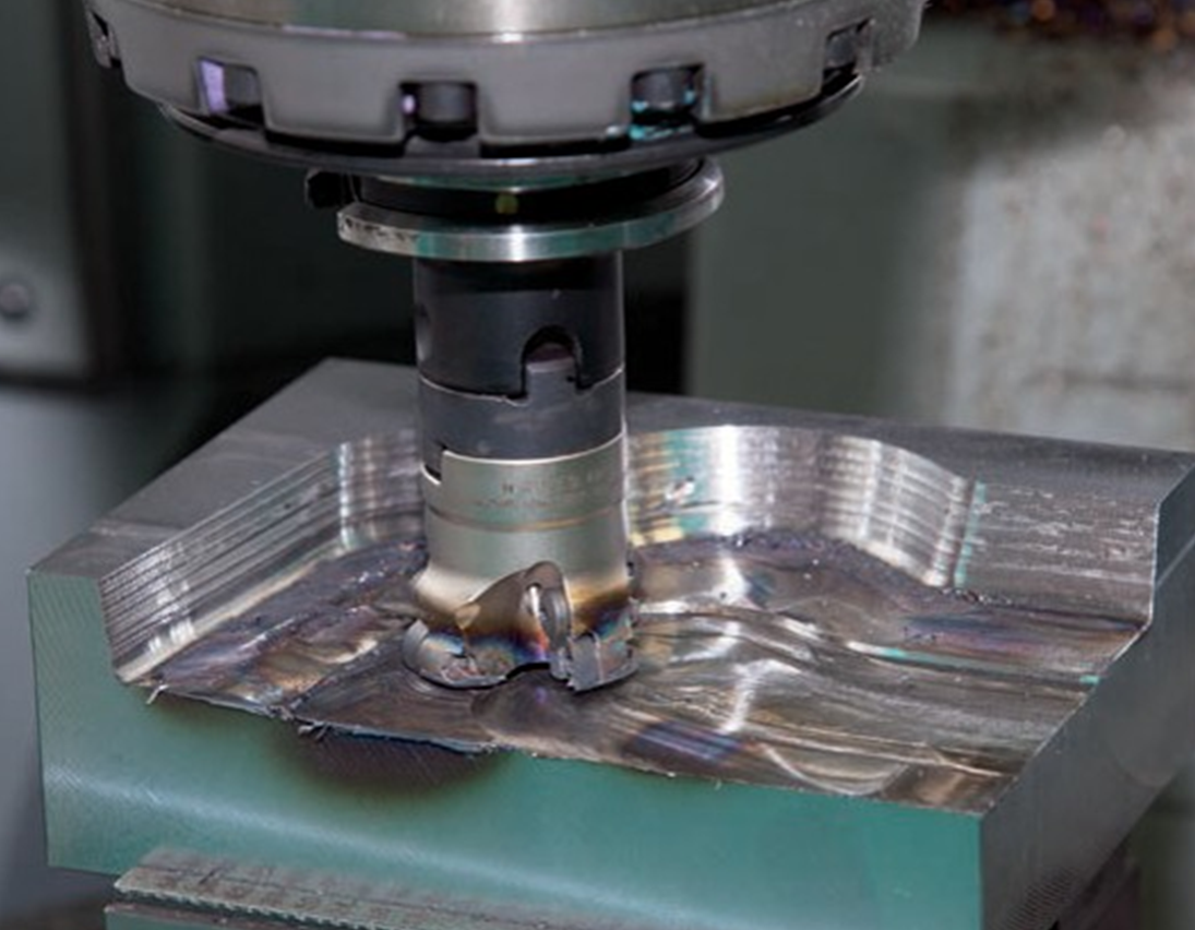
4 Ways to Prevent Tool Breakage
1) According to the characteristics of materials and parts to be processed, rationally select the types and grades of tool materials. Subject to having a certain hardness and wear resistance, the tool material must have the necessary toughness.
2) Select the geometric parameters of the tool reasonably. By adjusting the front and rear angles, main and auxiliary deviation angles, edge tilt angles and other angles, the cutting edge and tip of the tool are ensured to have good strength. Grinding a negative chamfer on the cutting edge is an effective measure to prevent tool collapse.
3) Ensure the quality of welding and sharpening to avoid various defects caused by poor welding and sharpening. Tools used in key processes should be ground to improve surface quality and check for cracks.
4) Choose the cutting amount reasonably and avoid excessive cutting force and high cutting temperature to avoid tool damage.
5) Try to ensure that the process system has good rigidity and reduces vibration.
6) Adopt correct operating methods and try to prevent the tool from bearing sudden or lower loads.
5 Causes and measures to take in case of tool chipping
1. Incorrect selection of blade quality and specifications, such as the blade thickness is too thin or too hard and brittle quality is selected for rough machining.
Countermeasures: Increase the thickness of the blade or install the blade vertically and choose a grade with higher bending resistance and toughness.
2. Improper selection of tool geometric parameters (such as too large front and rear angles, etc.).
Countermeasures:
You can rethink the tool in the following aspects.
1) Appropriately reduce the front and rear angles.
2) Use a larger negative edge angle.
3) Reduce the main deflection angle.
4) Use a negative chamfer or larger edge arc.
5) Grind the transition cutting edge and reinforce the tool tip.
3) The blade welding process is incorrect, causing excessive welding stress or welding cracks.
Countermeasures:
1) Avoid using a blade slot structure closed on three sides.
2) Select the weld correctly.
3) Avoid using oxyacetylene flame to heat welding, and keep it warm after welding to eliminate internal stress.
4) Use mechanical clamping structures whenever possible
4. Improper sharpening method will cause grinding stress and grinding cracks; after sharpening the PCBN cutter, the vibration of the teeth will be too great, resulting in overloading of individual teeth, which will also cause the knife to break.
Countermeasures:
1) Use interrupted grinding or diamond wheel grinding.
2) Use a softer grinding wheel and trim it regularly to keep it sharp.
3) Pay attention to the quality of sharpening and strictly control the amount of vibration of the cutter teeth.
5. The selection of cutting quantity is unreasonable. If the quantity is too large, the machine tool will be boring when cutting intermittently, the cutting speed is too high, the feed quantity is too large, and the gross margin is uneven. the cutting depth is too low; cutting high manganese steel. When materials with a strong tendency to work hardening are used, the feed amount is too small, etc.
Countermeasure: Reselect the cutting amount.
6. Structural reasons such as uneven bottom surface of mechanically clamped tool groove or blade too long.
Countermeasures:
1) Cut the bottom surface of the tool groove.
2) Arrange the position of the cutting fluid nozzle reasonably.
3) Hardened tool holder adds a carbide seal under the blade.
7. Excessive tool wear.
Countermeasures: Change the tool or cutting edge in time.
8. Insufficient coolant flow or incorrect filling method may cause sudden heat and blade cracking.
Countermeasures:
1) Increase the flow rate of the cutting fluid.
2) Arrange the position of the cutting fluid nozzle reasonably.
3) Use effective cooling methods such as spray cooling to improve the cooling effect.
4) Use *cutting to reduce the impact on the blade.
9. The tool is installed incorrectly, for example: the cutting tool is installed too high or too low; end mill uses asymmetrical milling, etc.
Countermeasure: Reinstall the tool.
10. The rigidity of the process system is too low, causing excessive cutting vibration.
Countermeasures:
1) Increase the auxiliary support of the workpiece and improve the clamping rigidity of the workpiece.
2) Reduce the length of the tool overhang.
3) Reduce the tool clearance angle appropriately.
4) Use other vibration absorption measures.
11. Careless operation, such as: when the tool cuts in the middle of the workpiece, the tool moves too hard before retracting;
Countermeasures: Pay attention to the operation method.
6 Causes, characteristics and control measures for built-up edges
1. Causes of formation
In the part near the cutting edge, in the tool-chip contact area, due to the strong downward pressure, the underlying metal of the chip is embedded in the uneven microscopic peaks and valleys of the cutting surface, thus forming a real metal. -metal contact without gaps and causing bonding, this part of the tool-chip contact area is called bonding area. In the bonding area, a thin layer of metallic material accumulates on the lower layer of the chip and remains on the inclined face. The metal material in this part of the chip has undergone significant deformation and is strengthened under appropriate cutting temperatures. As the chips continue to flow and pushed by the subsequent cutting flow, this layer of stagnant material will slide relative to the top layer of chips and separate, becoming the basis of the built-up edge. Subsequently, a second layer of accumulated cutting material will form on it, and this layer of continuous accumulation will form an accumulated edge.
2. Characteristics and impact on cutting processing
1) The hardness is 1.5-2.0 times that of the workpiece material. It can replace the rake face for cutting. Its function is to protect the cutting edge and reduce wear on the rake face. falls, debris flows through the tool-workpiece contact zone, causing wear on the sides of the tool.
2) After the built-up edge is formed, the working rake angle of the tool increases significantly, which plays a positive role in reducing chip deformation and cutting force.
3) Since the built-up edge protrudes beyond the cutting edge, the actual cutting depth increases and affects the dimensional accuracy of the part.
4) The accumulated edge will cause a “furrow” phenomenon on the workpiece surface, affecting the roughness of the workpiece surface.
5) The accumulated edge fragments will bind or embed in the workpiece surface to form hard spots, affecting the quality of the machined surface of the workpiece.
From the above analysis, it can be seen that built-up edges are detrimental to cutting processing, especially finish machining.
3. Control measures
The generation of built-up edges can be avoided by not sticking or distorting the underlying material from the chip to the cutting surface. Therefore, the following measures can be taken.
1) Reduce the roughness of the rake surface.
2) Increase the cutting angle of the tool.
3) Reduce the cutting thickness.
4) Use low speed cutting or high speed cutting to avoid cutting speeds that easily form built-up edges.
5) Proper heat treatment of the workpiece material to increase its hardness and reduce its plasticity.
6) Use cutting fluids with good anti-stick properties (such as extreme pressure cutting fluids containing sulfur and chlorine).
Daguang focuses on providing solutions such as precision CNC machining services (3-axis, 4-axis, 5-axis machining), CNC milling, 3D printing and rapid prototyping services.
