Master the art of CNC machining: a basic guide to your tool parameters
In the high-risk world of CNC machining, accuracy is crucial, efficiency promotes profitability, and understanding the complex dance between cutting tools and workpieces is fundamental. Tool parameters are not only numbers that enter the controller; they are the language that determines your success. Choosing the best tool and configuring its parameters correctly affects everything from surface surface and dimensional accuracy to tool life, cycle time and ultimately your project budget.
At Greatlight, as a professional five-axis CNC machining manufacturer, we witness every day how tool parameters are transformed into solving complex metal parts manufacturing challenges. We use advanced five-axis equipment and a wide range of production technologies to leverage this knowledge to provide accuracy and value. This guide delves into key CNC tool parameters to enable you to understand "Why" later "What" On the store floor.
Deconstructing CNC tools: Key parameters to explain
Think of cutting tools as athletes performing complex movements. Its performance depends on its inherent functionality (the athlete’s physique and training), and how you guide it to move during operation:
-
Tool Material: The Basics of Performance
- High-speed steel (HSS): Experienced veteran. Affordable, tough and tolerant work less work or cuts of softer materials. But low thermal resistance limits its speed.
- Carbide (tungsten carbide): Main champion. Provides a special balance of hardness, wear resistance and heat resistance. Ideal for high-speed processing of steel, stainless steel, cast iron and many nonferrous alloys. Various available "grade" Optimized for different material groups or processing strategies (e.g., high level vs. high clothing).
- Cermet & Ceramics: High performance expert. Cermets (ceramic + metal) have high wear and good surface effect, but are less tough. All ceramics (such as alumina or silicon nitride) are excellent in high-speed finishing of hardened steels and superalloys due to their extreme heat resistance, but are brittle.
- Polycrystalline diamonds (PCD): Challenges for abrasives. Unrivaled wear resistance when processing abrasive non-productive alloys (ALSI, MMC), composites and graphite. Excellent finish.
- Cubic boron (CBN): The hardest hitter. Second only to hardness diamonds. Designed specifically for work-hardening materials (HRC 45+) for carbide failures. Provides excellent tool life and finish in hard rotation and milling.
-
Tool Geometry: The Art of Cutting
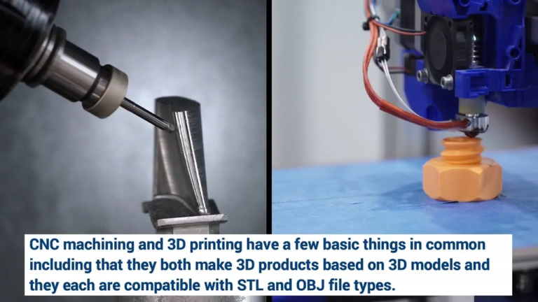
- Tool type: End mill (flat, ball nose, angular radius, chamfer, etc.), drill bits, reamers, faucets, inserts…each designed for specific operation and geometry (e.g. ball nose for 3D contours, for 3D contours, high feed mills, for effective roughness).
- diameter: Determines strength, material removal rate (MRR), coverage, and ability to process small features. Larger diameter = higher rigidity and MRR, but struggles in small details and deep pockets.
- Number of flutes: Affects chip evacuation, tool stiffness and achievable feed rate. More flutes = smoother finish, better surface quality, slower material removal (thinner). Less flutes = better chip clearance, higher feed rate per tooth and higher MRR, especially in adhesive materials.
- Helical angle: Control cutting force, chip evacuation and chat trends. Higher helices (~40°+) improve surface finish, promote chip evacuation, and reduce radial forces for surrounding milling, but can increase axial forces. The lower helix (<30°) is stronger for slots and harder materials.
- Flute length and coverage: Determine the depth at which the tool can cut. It is crucial for cavity work. Longer tools vibrate more – use the shortest effective length.
- Core diameter: Thicker core = greater tool stiffness and resistance to deflection/vibration. Thinner core = larger esophagus for evacuating chips.
- Tip Preparation (Hungry/Edge Preparation): A tiny, controlled radius on the tip (K-Land, T-Land). Sharply affects the lifespan and edge strength of the tool, especially in the case of high-performance cutting and cutting interruptions. Larger abrasiveness increases strength, but can increase cutting force.
-
Tool Paint: Thermal and Tribological Shield With PVD or CVD applications, the coating is a thin layer that significantly enhances the performance of the basic material.
- Tin (titanium nitride): Classic gold coating. Good versatile wear resistance.
- tialn (titanium aluminum): Ideal for high-thermal applications such as steel and cast iron. A protective alumina layer is formed at high temperatures. Good toughness.
- TICN (Titanium Carbon Dititanium): Harder than tin, more wear-resistant, suitable for abrasive materials and higher speeds. A little less.
- Altin (aluminum-titanium): The content is higher than tialn. High-quality thermal hardness and oxidative resistance in extremely harsh conditions (hard grinding, high temperature alloys, dry processing).
- Diamond paint: Applied to carbide tools, providing extreme wear resistance when processing non-productive alloys and composites. Avoid using steel/ferrous metals.
- Function: The coating increases surface hardness, reduces friction/heat generation, improves wear and oxidation resistance, and acts as a thermal barrier. Choosing the right coating is critical to extend tool life and achieve higher speeds/feeds.
- Cutting parameters: Set pace
- Cutting speed (VC): The speed at which the tool edge passes over the workpiece (SFM-per minute or m/min). Drive heat generation. The reason for being too low is building edges; too high can lead to rapid wear or tool failure. Mainly by Workpiece material and Tool Materials/Coatings.
- Feed rate (each tooth-fz feed): Tools per revolution (inch/teeth or millimeter/teeth) the tool moves away. Drive material removal rate and chip thickness. Too low can lead to friction and premature wear; too high can lead to tool breakage or mismatch. Affected by workpiece material, tool stiffness, cutting width/depth, clamping and required finish.
- Spindle speed (RPM): The spindle rotates every minute. Calculated based on cutting speed and tool diameter:
RPM = (Vc * 12) / (π * Diameter [inches])orRPM = (Vc * 1000) / (π * Diameter [mm]). - Feed rate (IPM or mm/min): Linear velocity of tool movement. calculate:
Feed Rate = RPM * Number of Flutes * fz. - Cutting depth (axial-AP, radial-AE): How much material is removed from the z-axis (AP) and lateral (XY-AE). Control MRR and tool loading. Deep/width cutting requires conservative speed/feed and robust tools/settings. Light cutters can use more positive parameters.
Symphony of parameters: Effect on results
Incorrectly judging these parameters has tangible consequences:
- Poor surface effect: The reason may be that the feed is too high (Feed line), error tool geometry for operation (e.g. flat end mill for finishing curvature), wear tool (chatter) (vibration), incorrect chip formation (friction).
- Inaccurate dimensions: Caused by tool deflection (overcut depth/width, fragile tool holder, blunt tool), thermal expansion (coolant failure, excessive VC), or vibration.
- Premature tool wear/malfunction:
- Abrasive wear: Incorrect grade of abrasive material/coating, over-high speed of coating limit, chip recovery blunt edges.
- Thermal cracking/deformation: Overcut speed (heat), insufficient coolant.
- Edge debris/break: The feed rate is too high, the cutting depth/width is too much, the tool is too long/weak, vibration, and the material is weak (toughness problem).
- Build edges: The material is welded to the edge. Too low cutting speed, low feed rate, incorrect geometry/coating of viscous material (aluminum).
- chatter: Visible vibration marks on the workpiece; audible noise. The speed or feed caused by tool/material harmonics, insufficient tool/workpiece stiffness, and insufficient tool path strategy. Destroy tool life and parts.
- High cost per section: Inefficient material removal (MRR), frequent tool replacements, cancellation of parts and wasted machine time all increase costs.
Five-axis advantages and nuances of parameters
Five-axis machining unlocks complex geometric shapes, but also adds layers for parameter selection:
- Variable participation angle: As the tool tilts, the effective radial and axial depth of rotation relative to the axis varies. Parameters optimized for vertical end mills may cause tremors or deflections in the tilted position. Dynamic feed rate regulation within the tool path can help.
- Reduced vibration risk: Complex contours naturally avoid problematic harmonic areas, but programmers must understand tool dynamics across directions.
- Axis clearance and collision: Longer tool dangling may be required to clear the fixture in the inclined position, thereby increasing the risk of deflection. This may require a lower feed rate or a dedicated tool holder.
- Rate reduction optimization: Five axes allow optimal tool orientation to maximize material removal, thus opening the door for the use of high-performance tools such as barrel cutters, which is impossible on 3 axes. Optimizing the parameters of these tools is key.
- Simulation is crucial: Advanced CAM simulations, including material removal and machine kinematics, are critical to foreseeing and optimizing cutting conditions throughout the tool path.
Optimization for Successful: Great Ways
Achieving peak performance is not a guess. This is a fusion of science, data and deep experience:
- Know your materials: Material characteristics (hardness, toughness, thermal conductivity, wear, adhesiveness) determine the starting point of tool selection and parameters.
- Utilize manufacturer data: Well-known tool suppliers provide detailed initial advice for VC and FZ. Use these charts as your basis.
- Begin conservatively and actively optimize: Start with the recommended parameters. If stability, finish and tool life are good, please add FZ with caution, then VC within the paint limit, or increase depth/width. Strictly monitor tool wear and part quality. Univariate testing is key.
- Priority to chip control: An effective evacuation prevents tool damage and ensures continuous cutting. Ensure adequate coolant flow (need to flood or high pressure through the tool if needed) or effective air explosion, especially in the 5-axis path of turbulent flow. Use Chipbreaker geometry.
- Embrace rigidity: Use shrink fusion, hydraulic or high-precision milling and paint. Minimize tool drape. Make sure the workpiece fixtures are bulletproof. Rigidity is the enemy of chatting and deflection.
- Wire Harness Technology: Advanced CAM systems provide dynamic feed rate optimization, vibration damping tool path (Trochoidal, adaptive clearance) and complex simulation software packages. The cutting force monitoring system provides real-time feedback.
- Documentation, analysis, iteration: Record your parameters, tool life, and any issues you encounter. Analyze the failure mode. Continuous improvement is crucial.
Conclusion: Master the accuracy of the design through parameters
Understanding CNC tool parameters is more than just a technical term; it is the nature of an efficient, high-quality and cost-effective manufacturing industry. Select the correct tool material, geometry and coating and then dial at optimal cutting speed, feed speed and cutting depth to form the successfully processed bedrock. This knowledge is exponentially amplified on the complex high potential stage of five-axis CNC machining.
At Greatlight, this mastery is at the heart of our DNA. We combine state-of-the-art five-axis CNC machining equipment, in-depth material science knowledge and a wide range of production technology experiences to meet your most challenging metal parts. From choosing the perfect tools and parameters from the door to iteration for peak performance, our goal is to deliver precision parts with unparalleled quality, speed and value.
Ready to experience Greatlight Advantage? Upload your design and get a quote now.
FAQ (FAQ)
-
Q: Why does my tools wear out so quickly?
- one: This may be due to several factors: overcut speed (VC), overly aggressive feed (FZ), insufficient or ineffective coolant application, incorrect tool material for tool material/coating, poor chip evacuation resulting in recycling, excessive radial or axial cutting or processing of highly ground material.
-
Q: How to improve the surface finish?
- one: Focus on: Reduce each tooth (FZ), select tools with higher flute counts and sharper edges to ensure the right tool type (e.g., ball nose in 3D), increase step (reduce radial depth) for completion verification, for completion of fixation, enhance rigidity (tool holder, set), and eliminate vibration (change vibration) (optimal fixation amount), use vibration (optimal tool/tool), certain fixation (optimal tool), a uniform fixation effect, a good fixation effect, a good fixation effect (optimal tool), a certain temperature control.
-
Q: I’m chatting – What should I do?
- one: Chat comes from vibration resonance. Solution: Increase spindle speed or reduce feed rate (FZ) to remove the harmonic area. Fundamentally shortens tool extensions. Use tools with thicker core diameters or larger calfs. Improve workpiece clamping stability. Consider the damping tool holder (anti-vibration). Use a tool path strategy designed specifically to minimize vibration (Trochoidal milling, changing stepover/z-step).
-
Q: How important is coolant really?
- one: Crucial! Coolant (or MQL/dry air explosion) has important functions: dissipate heat generated at the forefront, lubricate the chip tool interface to reduce friction/heat (especially important for aluminum), flush debris to prevent damage and protect the finished surface. Choosing the right type (oil, lotion, synthesis) and application method (flood, through tools) is key.
-
Q: What makes five-axis machining different from tool parameter selection?
- one: Five axes introduce variable tool orientation. This means that effective cutting speed, radial/axial engagement and tool stiffness can vary dramatically throughout the tool path. Parameters optimized for one direction may cause problems in the other direction (deflection, chat uneven). Using cam simulation and dynamic feed rate adjustment becomes critical. Less rigid settings may require dialing back parameters at certain locations.
- Q: Can Greatlight help me optimize tool parameters for a specific part?
- Answer: Absolutely! This is the core part of our expertise. Our engineering team analyzes your part geometry, materials, tolerance and finish requirements to select the best tools and use advanced CAM systems and our in-depth process knowledge to program the most efficient and reliable machining parameters. We deal with technical complexity so that you can get the best results.
