
Unlocking complex geometry: Your in-depth guide to 4-axis CNC programming
Going beyond the limitations of traditional 3-axis machining, 4-axis CNC machining introduces a world of increased complexity, efficiency and design freedom. For manufacturers and engineers dealing with complex prototypes, complex components or demanding production runs, mastering 4-axis programming is not only beneficial—usually essential. At Greatlight, we take advantage of the cutting-edge five-axis functionality every day, and we understand the power and nuances of multi-axis machining. This guide delves into 4-axis CNC programming, providing the basics you need to effectively utilize this technology.
What exactly is 4-axis CNC machining?
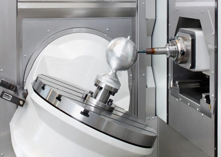
On its core, a 4-axis CNC machine adds a rotation axis (commonly referred to as A-axis or B-axis) to the standard linear X, Y, and Z motions in a 3-axis computer. This rotation axis causes the workpiece to rotate dynamically during machining.
- The fourth axis mechanism: It is usually achieved with a rotating table mounted on a machine tool bed or on a stand-alone rotating head. The workpiece is securely clamped to the rotating device.
- Rotate Free: The A-axis usually rotates around the X-axis, while the B-axis rotates around the Y-axis. The machine is usually designated as "x/y/z/a" or "x/y/z/b". This controlled rotation can be processed on multiple faces without manual repositioning of the parts.
Why choose 4 axes on 3 axes? Key Advantages
The introduction of the fourth axis strategy unlocks significant benefits:
- Reduced settings and improved accuracy: Complex parts that require features on multiple sides (e.g. slots on cylinders, spiral features, contours around objects) can often be machined in a single setup. This eliminates cumulative errors from multiple repositioning and fixing devices.
- Complex geometric capabilities: Create features such as cam lobes, complex curves on cylindrical surfaces, spiral paths (threads, flutes), tilted holes and undercuts, making it easier and more precise.
- Enhanced finish: The continuous tool path wrapped around the rotating part will usually be smoother on the curved surface than the discrete progressive method using the 3-axis.
- Improve productivity: Fewer settings translate directly into reduced overall machining time, faster throughput and lower labor costs.
- Wide design feasibility: Enables designers to create parts produced using only the 3-axis method.
When do you need 5 axes? While 4-axis is powerful, 5-axis machining (adding a second simultaneous rotational axis) is crucial for highly organic, engraved surfaces (such as impellers or turbine blades) that require extreme filtration or machining.
Core components of 4-axis programming: Beyond G00 and G01
4-axis programming is not only Add a rotation command. It requires a fundamental change in thinking:
- Working coordinate system (WCS) master: Accurately define the relationship between the coordinate system of the machine, the center line of the rotation axis and the partial geometry The most important. The error here leads to scrap parts.
- Rotate axis command: Familiar with specific G-codes used by machines for rotational motion (e.g.
G0 A90.0Quickly rotate to 90 degrees). It is crucial to understand Positioning (index) and Continuous and simultaneous movement:- index: The fourth axis rotates the part to a specific fixed angle, locks, and then 3-axis machining occurs (e.g., milling features on different sides of the cube). Simpler programming, usually using standard 3-axis tool paths.
- Continuous/simultaneous fourth axis milling: Rotating shaft moves continuously although The X, Y and Z axes move simultaneously, allowing the tool to follow complex contours around the part (e.g., machining CAM contours). Advanced CAM software and careful programming are required to avoid mining and management tool directions.
- Tool route strategy: CAM software is essential for complex 4-axis simultaneous operation. Key strategies include:
- Packaging tool path: Use the rotation axis to project a 2D tool path (such as engraved text or slot pattern) onto a cylindrical surface.
- Slaw Milling: Use one side of the tool when the rotation axis is effectively moved to the machine’s cylindrical or conical surface.
- Multi-axis profile: Directly control tool movement along the 3D path while rotating movement – the core of 4-axis machining at the same time.
- Tool Center Point Control (TCPC) / RTCP: For machines equipped with this feature, the control system dynamically adjusts the linear axis to compensate for the tool tip position as the rotation axis moves. Simplify programming by allowing programmers to focus on tool tip paths relative to the motion chain of parts rather than machines. Verify that your machine/control supports this.
- Avoid collisions: This becomes even more important on the 4 axis. Rotation introduces new potential collision points between tools, brackets, spindles, and workpieces or fixtures. The simulations in your CAM software are not negotiable. Manually check the clearance of extreme rotation positions.
Programming in Practice: A Step-by-Step Overview
- Define geometry and requirements: A clear understanding of part design, key features and tolerances. Determine which functions require 4-axis motion.
- Select Fixed and Settings: Design a solid fixture that securely holds the parts and provides clear access to the tool path. Accurately position the center of the rotation axis relative to the part reference.
- Select a processing strategy: Determined between indexing and simultaneous machining for each operation. The order of operations is planned logically.
- Cam Programming:
- Correctly import and direct CAD models.
- Defines the machine configuration and rotation axis type/position in the cam system.
- Set the WCS origin and align it with the rotation center and part of the reference.
- Select the appropriate 4-axis (or multi-axis) toolpath policy for each function.
- Consider changing angles of participation and define cutting parameters (speed, feed, steps).
- Configure axis limits and collision checks.
- Complete simulation: Run detailed machine simulation in CAM software. Check for collisions, excessive travel restrictions, rotation and verify tool path correctness all Rotate position. Never skip this step!
- Post-processing: Generate machine-specific G-code using a proven postprocessor configured for your precise machine control and rotary axis settings. This kind of translation is crucial – generic posts are not enough.
- Machine Settings and Settings Table: The workpieces, tools and fixtures are actually set according to the planned WCS. Provides clear set-up boards for machine operators.
- prove: Run the program with caution! First use the reduced feed rate, perform block by piece, ideally, verify the tool path on the waste material first. Monitor accidental movements or collisions closely. Adjust the offset as needed.
Overcome common 4-axis programming challenges (Greatlight Insights)
- Rotating centerline accuracy: Even a slight misalignment can lead to huge errors. Invest in accurate fixed and meticulous setup verification (using dialing metrics, probe cycles).
- Tool length and gap: It may take longer tools to achieve certain functions after rotation. Always model and simulate tool components in CAM to ensure clearance.
- Part deflection: During rotation, thin-walled or cantilevered parts can be deflected under cutting forces. Adjust feed/speed or use support carefully.
- Programming complexity of simultaneous paths: Leverage high-quality CAM software dedicated to multi-axis tool paths. Break down complex parts into manageable operations.
- Postprocessor reliability: Bad after-processors are the main source of crashes. Invest in your specific machine control portfolio customization or purchase verification posts. At Greatlight, we continuously improve the reliability of internal postal processors.
Why do you need the Greatlime collaboration for your 4-axis (and later) CNC?
Using true expertise and advanced infrastructure can lead to unparalleled results while mastering 4-axis programming. Greglight is your ideal partner:
- Depth multi-axis expertise: We not only run 5-axis machines; our engineering team has a deep understanding of multi-axis kinematics, programming (including 4-axis), machining strategies and troubleshooting. This expertise translates into optimized procedures and perfect execution.
- The most advanced technology: We are constantly investing in advanced multi-axis CNC machining centers that enable high-precision indexing and complex 4-axis and 5-axis movements, ensuring we can handle the most demanding work.
- End-to-end solution: From the initial DFM consultation to take advantage of the multifunctional benefits, through expert CAM programming and meticulous process inspection, to comprehensive post-processing (anodizing, plating, painting, painting, assembly), we provide the parts ready to be used.
- Material versatility and speed: We process many metals and plastics efficiently. Our streamlined processes and centralized expertise enable truly fast custom machining without compromising quality.
- Commitment to value: Advanced features don’t have to mean high costs. Our effective operation and quantity leverage enables us to provide competitive, best-value pricing for precise 4-axis and 5-axis custom parts.
Conclusion: Use the fourth dimension to improve manufacturing
4-axis CNC programming represents an important step in machining capabilities. By mastering the rotation of the workpiece about a single axis, manufacturers can generate complex geometric shapes more accurately and efficiently on 3-axis machines. Understanding core concepts such as WCS alignment, rotation indexing and simultaneous motion and the key role of collision avoidance is crucial. Despite the increased complexity of programming, the benefits of design freedom, reduced settings and excellent surface quality are undeniable.
For projects that require 4-axis (or even 5-axis) machining capabilities, working with experienced precision manufacturers such as Greatblay to reduce risks ensures risks and ensures optimal results. We bring together cutting-edge technology, deep multi-function expertise, full service and commitment to value position, the ideal solution for complex custom parts manufacturing. Ready to use the fourth dimension? Contact Greatlight now to discuss your precise CNC machining requirements.
FAQ (FAQ)
Q1: What is the main difference between a 4-axis machine and a 5-axis machine?
A: The 4-axis machine adds a rotation axis (such as A or B) to the X, Y, Z motion. A 5-axis machine has been added second The rotation axis (such as A and C or B and C) allows the cutting tool to approach the workpiece from almost any direction at the same time. This can significantly complex geometry, eliminate more settings, and allow advanced techniques such as shorter tools to improve rigidity.
Q2: Is 4-axis CNC machining always better than 3-axis?
A: This is not always the case. If your part is essentially prismatic (flat sides at 90 degrees) and does not require features on curved surfaces or angular planes, a 3-axis machine may be simpler and faster. 4 axes are to truly glow when the part has parts that need to be rotated to continuously access multiple sides or need to be wrapped/milled.
Q3: Can I use regular 3-axis CAM software for 4-axis programming?
Answer: Limited index operations. The 3-axis software can generate code for machining at a specific fixed rotational position (e.g., machine side A, then rotate 90 degrees, machine side B). But, Continuous and 4-axis machining Where rotation and X/Y/Z motion are simultaneously performed, you absolutely need dedicated multi-axis CAM software that can generate complex coordinated tool paths and manage tool orientations.
Question 4: What is the biggest challenge in 4-axis programming?
A: The main challenges include:
- Ensure absolute accuracy of aligning the centerline of the rotary axis with the part reference (WCS settings).
- Prevent collisions between tools/brackets/spindles and parts or fixtures during rotation (advanced simulation is required).
- As the cutting angle changes continuously during simultaneous motion, the interaction and deflection of the tools are managed.
- Generate error-free G-codes through a reliable, machine-specific postprocessor.
Q5: Can Greatlight help optimize my 4-axis machining design?
Answer: Absolutely! Manufacturing Design (DFM) is the cornerstone of our service. Our experienced engineers can review your design early in the process, suggesting modifications to take advantage of 4-axis benefits (such as reducing setup or enabling complexity), improve machining, improve stability, and ultimately optimize costs and lead times.
Q6: How to get a quote for the custom 4-axis CNC machining section?
A: It is very easy to get a quote. Visit the Greatlight website and upload your CAD file (e.g., steps, IGES, X_T). Details such as materials, quantity, required tolerances, finishes and any aftertreatment requirements are provided. Our team of experts will analyze your project and quickly provide valuable DFM insights.



















