
CNC Robot Parts Processing for Joints, Housings and End Effectors
Robot builders and integrators use this page to judge which arm components belong on a 5-axis mill-turn center and which do not. We cover datum strategy, wall thickness limits, bearing-bore tolerances and the materials that survive repeated impact loads.
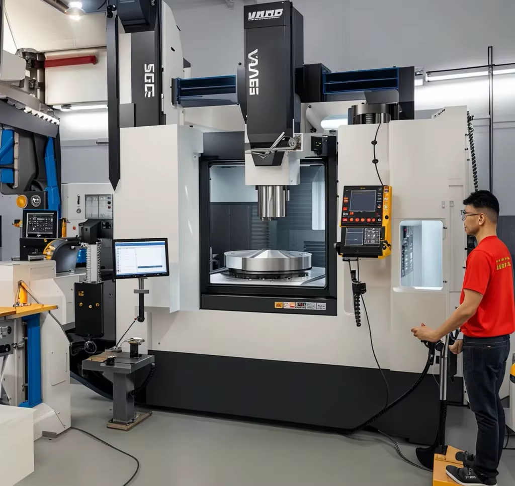
Why CNC robot parts processing Needs 5-Axis Setup
A robot arm is a stack of rotating joints. Each joint carries a bearing bore, a motor mounting face and a set of bolt holes that must stay concentric after assembly. If those features are cut in separate setups on a 3-axis machine, every re-clamp adds stack-up error. On a 6-axis arm with 300 mm of reach, a 0.02 mm bore offset becomes visible backlash at the tool tip. That is why most joint housings are cut in one or two 5-axis setups.
A simultaneous 5-axis center keeps the part on one datum while the spindle reaches five faces. We machine the bearing bore, the shoulder face and the motor pilot in the same operation, so the runout between them comes from the machine, not from the fixture. On our Ø400 mm rotary tables, a typical aluminum joint housing holds ±0.005 mm on bore position and ±0.01 mm on face runout.
The trade-off is programming time. A 5-axis toolpath for a thin-wall housing can take 3 to 6 hours to verify in simulation. That cost only pays back when the part has tight concentricity, deep pockets or features on more than three faces. For a simple bracket, 3-axis is still faster and cheaper.
- 1One datum, five facesBore, pilot and mounting face cut without re-clamping.
- 2Runout under control±0.01 mm face runout on Ø400 mm rotary table work.
- 3Where it does not payFlat plates and 2-face brackets stay on 3-axis.
Joint Housings, Harmonic Drive Cups and End Effectors
Harmonic drive cups are the hardest common robot part. The flexspline wall often runs 0.8 to 1.5 mm thick, and the gear teeth must sit within 0.02 mm of the bearing bore center. Cutting that wall generates heat, and heat moves the part. We rough with a 12 mm end mill at 0.3 mm radial engagement, leave 0.4 mm stock, then finish with a 6 mm tool at 0.08 mm stepover and high-pressure coolant. Between roughing and finishing the part rests for 2 hours so the temperature equalizes.
End effector plates are easier but more varied. Gripper mounts, camera brackets and tool changers mix tapped holes, dowel pin bores and clearance slots on one plate. Position tolerance on dowel bores typically runs ±0.01 mm; tapped holes can sit at ±0.1 mm. We separate those tolerance bands in the drawing so the operator knows which features get probing and which get a caliper check.
Arm links sit in between. They are long, often 200 to 600 mm, and stiffness matters more than absolute accuracy. A link that flexes 0.05 mm under a 20 kg payload will show up as vibration at the end effector. Ribbed aluminum links machined from 7075-T6 hold stiffness better than flat plates, but 7075 costs more and welds poorly if the design later switches to fabrication.
- 1Flexspline cups0.8–1.5 mm walls need light finishing passes and rest time.
- 2End effector platesMixed tolerance bands: dowel bores tight, clearance holes open.
- 3Arm linksStiffness drives the material choice, not just the tolerance.
Material Choices for Robot Arm Components
Aluminum 6061-T6 covers most arm links, joint covers and end effector plates. It machines fast, anodizes cleanly and holds ±0.01 mm without drama. When weight is the binding constraint, 7075-T6 gives roughly 30% higher yield strength at similar density, but it is less forgiving on thin walls and harder to anodize to a uniform color.
Steel enters when the part carries the bearing directly. Bearing bores in 4140 or 4340 hold their size through press fits and repeated load cycles. Stainless 17-4PH (SUS630) is common in food-handling and medical robots because it resists corrosion and can be heat treated to 40 HRC. For high-wear surfaces such as cam tracks, 440C or tool steel with a black oxide finish lasts longer than any aluminum option.
Titanium TC4 (Ti-6Al-4V) shows up in legged and humanoid platforms where the strength-to-weight ratio justifies the cost. It cuts at roughly one-third the speed of aluminum, so cycle time and tool wear rise. Inconel appears only in hot-end or high-load joints, and it is a specialty job: slower spindle speeds, more tool changes, higher cost per part.
- 16061-T6Default for links, covers and plates.
- 27075-T6Higher strength, tighter process window, poorer anodize uniformity.
- 34140 / 4340Bearing bores and press-fit seats.
- 417-4PHCorrosion resistance plus heat treat to 40 HRC.
How Tolerance and Inspection Stack Up
Robot parts fail in the field for two reasons: backlash and fatigue. Backlash usually traces back to a bore that is out of round or a mounting face that is not square to the bore axis. Fatigue traces back to a sharp internal corner or a wall that is thinner than the drawing states. Both are catchable before shipment if the inspection plan matches the failure mode.
We inspect 100% of parts before shipment. Raw material certificates are checked on receipt. In-process monitoring covers bore size after boring and wall thickness after roughing. Final inspection includes CMM reports on critical bores and faces, plus a functional check on dowel pin fits. Reports go out on request; for a joint housing that means a bore roundness number, a face runout number and a hardness reading when the material is heat treated.
The tolerance floor is ±0.005 mm, but not every feature needs it. Putting ±0.005 mm on a clearance hole adds cost and inspection time for no gain. We ask customers to mark only the features that affect joint motion, and leave the rest at general tolerance.
- 1Roundness firstOut-of-round bores are the main source of backlash.
- 2Corner radiusSharp internal corners concentrate stress under cyclic load.
- 3Selective toleranceTight only where joint motion depends on it.
When CNC Machining Is the Wrong Process
Machining wins on low to medium volume, tight tolerance and complex geometry. It loses when the part is a simple shape made in the tens of thousands. A cast or forged joint housing with a few machined faces costs less per unit at that volume, even after tooling. We quote both routes when the geometry allows it.
Very thin walls have a floor. Below about 0.5 mm in aluminum, chatter and distortion make the result unpredictable. If a design needs a 0.3 mm flexure, it usually belongs in sheet metal or a stamped flexure, not a milled pocket.
Internal channels are another boundary. A straight drilled cross-hole is routine. A curved cooling channel inside a joint needs additive manufacturing, because no end mill can reach around the bend. We route those parts to our 3D printing service and machine the critical interfaces afterward.
- 1High volume simple shapesCasting or forging plus finish machining costs less.
- 2Walls under 0.5 mmChatter and distortion make the result unreliable.
- 3Curved internal channelsAdditive manufacturing, then machine the interfaces.
Robot Part Features and the Right Process
Match the feature to the process before you request a quote.
| Feature | Typical tolerance | Best process | Watch out for |
|---|---|---|---|
| Harmonic drive cup | ±0.01 mm bore | 5-axis mill-turn | Wall thickness under 0.8 mm |
| Joint housing | ±0.005 mm bore | 5-axis | Re-clamping kills concentricity |
| Arm link | ±0.05 mm | 3-axis or 4-axis | Stiffness, not accuracy, drives design |
| End effector plate | ±0.01 mm dowel bores | 3-axis | Mixing tight and loose tolerance bands |
| Bearing seat in steel | ±0.005 mm | 4-axis turning | Press-fit distortion after heat treat |
| Gripper jaw | ±0.02 mm | 5-axis | Wear surface needs hardening |
| Curved cooling channel | N/A | 3D printing | Machine interfaces after printing |
Pick the process by feature, not by habit
If the part carries a bearing bore and a mounting face on different sides, put it on a 5-axis center. If it is a flat plate with clearance holes, a 3-axis machine will match the tolerance at lower cost.
Common questions about CNC robot parts processing
What wall thickness can you hold on a harmonic drive cup?
We hold 0.8 mm reliably in aluminum and 1.0 mm in stainless. Below that, the part deflects during finishing and the roundness number drifts.
If your design needs a thinner wall, we suggest roughing, a stress-relief rest, then a light finish pass with a 6 mm tool at 0.08 mm stepover.
Do you machine complete robot arms or only individual parts?
We machine individual components: joint housings, links, cups, end effector plates and gripper jaws. Assembly is handled by the customer or the integrator.
We can supply matched sets where bores and faces are cut in the same setup, which keeps concentricity between mating parts.
Which materials do you stock for robot joints?
Aluminum 6061-T6, 7075-T6 and 2024; stainless 303, 304, 316L and 17-4PH; steel 4140 and 4340; titanium TC4. Beryllium copper and Inconel are available on request.
Material certificates are checked on receipt and kept with the job record.
How do you handle confidentiality on a new robot design?
Uploads are secure and confidential. We sign an NDA on request before reviewing drawings.
We do not publish customer names or part photos without written permission.
What is the smallest order you accept?
There is no minimum order quantity. We run from one prototype to 10,000+ part runs.
Quotation and DFM analysis come back within 12 hours, and production can start within 24 hours of approval.
Can you hold ±0.005 mm on every feature?
We can hold ±0.005 mm on bores and faces that are cut in a single 5-axis setup and verified on a CMM.
Applying that tolerance to clearance holes adds cost with no functional gain, so we ask customers to mark only the features that affect joint motion.
Send your robot part drawings
Upload STEP files and get a quotation plus DFM feedback within 12 hours. No minimum order quantity.
12-hour quote100% inspectionNDA on request
More robot machining notes
We publish setup notes, tooling trials and inspection data from the factory floor.











