Explore CNC Meaning​ & CNC Technology

GreatLight’s blog aims to share our hard-earned knowledge on Explore CNC Meaning​ & CNC Technology. We hope these articles help you to optimize your product design and better understand the world of rapid prototyping. Enjoy!

CNC Knowledge: What should an excellent CNC operator pay attention to after processing is completed? Only then can you avoid problems!

CNC machining refers to a machining method that processes parts on CNC machine tools and uses digital information to control the movement of parts and tools. It is a method for solving the problems of variable varieties of parts, small batches, complex shapes and high precision. , and to achieve high efficiency and effective automation.

The processing procedures of CNC machine tools and traditional machine tool processing are generally the same. However, because CNC is one-time clamping and continuous automatic processing to complete all turning processes, there are some things that need to be paid attention to after processing. The CNC machine tool processing is completed.

Points to note after treatment:

1. Remove the chips, wipe the machine tool, and keep the machine tool and the environment clean.

2. Pay attention to check or replace the wiper plate on the worn guide rail of the machine tool.

3. Check the condition of lubricating oil and coolant, and add or replace them in time.

4. Turn off the power supply and the main power supply successively on the machine tool control panel.

5. When starting the machine tool, the principles of return to zero first (unless special requirements), manual, gradual and automatic should be followed. The operation of the machine tool should follow the principle of low speed, medium speed and then high speed. The running time of low speed and medium speed should not be less than 2-3 minutes. Only when it is determined that there are no anomalies can work begin.

6. It is strictly prohibited to strike, straighten or correct the workpiece on the chuck or between the centers. The part and tool must be confirmed as tight before proceeding to the next step.

7. The operator must stop the machine when changing tools, parts, adjusting parts or leaving the machine tool.

8. Operators are not allowed to dismantle or move the safety insurance and protection devices of the machine tool at will.

9. Before the machine tool starts processing, the program verification method should be used to check whether the program used is similar to the parts to be processed. After confirmation, the protection device can be closed and the machine tool can start processing. parts.

10. Machine tool accessories, measuring tools and cutting tools should be properly stored and kept intact and in good condition. No compensation will be required in the event of loss or damage.

11. After training, the machine tool should be cleaned and kept clean, the tailstock and carriage should be moved to the end of the bed, and the machine tool should be cut.

12. When a machine tool malfunctions or an abnormality occurs during work, it should be stopped immediately to protect the site and immediately reported to the responsible person on site.

13. Operators are strictly prohibited from changing machine tool parameters. If necessary, the device administrator should be notified and asked to change it.

14. Understand the technical requirements of the part drawing and check whether there are any defects in the size and shape of the blank. Choose a reasonable method of installing parts.

15. Select CNC turning tools correctly and install parts and tools accurately and firmly.

16. Understand and master the control and operation panel of the CNC machine tool and its essential operating elements, accurately enter the program into the system, simulate the inspection and cutting of the chamber, and carry out various preparations before the treatment.

17. If you find that the lathe makes abnormal noise or malfunction during processing, you should immediately stop the machine for inspection and report to the instructor to avoid danger.

Daguang focuses on providing solutions such as precision CNC machining services (3-axis, 4-axis, 5-axis machining), CNC milling, 3D printing and rapid prototyping services.

Automatic oil film feeder can adapt to different types of materials

Automatic oil film feeder can adapt to different types of materials

Automatic oil film feeder is a widely used device in automated production lines. It is mainly used to automatically feed various materials into processing equipment or production lines through a precise feeding mechanism. This type of equipment generally adopts the technical principle of oil film and uses the characteristics of oil film to transport materials smoothly and precisely, thereby improving production efficiency and precision.

  Automatic oil film feederMain features:
1. Efficient and smooth feeding performance: Through the lubricating effect of the oil film, smooth and resistance-free material transportation can be achieved. It can provide efficient feeding function without damaging the material surface and avoid instability problems caused by too much or not enough friction.
2. Reduce material wear: Oil film technology greatly reduces the friction between the material and the feed roller, reduces material wear during the transportation process, prolongs the service life of the material and reduces production costs.
3. Strong adaptability: able to adapt to different types of materials, including metal, plastic, paper, etc. Whether it is light materials or heavier materials, smooth conveying can be achieved through oil film feeding.
4. Precise feeding control: The equipment is equipped with a high-precision control system, which can monitor key parameters such as feeding speed and oil film thickness in real time to ensure the precision and stability of the feeding process. This is especially important for high-precision production processes, which can effectively reduce errors and waste during production.
5. Energy saving and environmental protection: By reducing friction, it reduces energy consumption and has high energy efficiency. In addition, compared to traditional mechanical lubrication, the use of oil film lubrication reduces the use of lubricating oil, thereby reducing the impact on the environment.
Application areas of automatic oil film feeder:
1. Metal processing industry: during stamping, shearing, curling and other metal processing processes, sheet metal can be accurately fed into the processing equipment to ensure the smoothness and accuracy of the process power supply.
2. Electronic manufacturing industry: In the production process of electronic components, tiny electronic parts (such as circuit boards, chips, etc.) can be accurately fed into the assembly equipment to ensure efficiency and the precision of the production process.
3. Plastic processing industry: In the production of plastic products, it can smoothly transport plastic sheets, films and other materials, avoiding material damage due to excessive friction.
4. Packaging industry: In the packaging industry, it can be used to introduce various packaging materials (such as cartons, plastic films, etc.) into the packaging equipment to ensure the smooth running of the packaging process.
5. Paper products industry: During paper production and processing, it can be used to roll paper in paper machines or other processing equipment to ensure precise transmission of materials during the paper process. production.
6. Food processing industry: In the field of food processing, it can be used to transport various raw materials and packaging materials to ensure the efficient operation of food processing production lines.

Daguang focuses on providing solutions such as precision CNC machining services (3-axis, 4-axis, 5-axis machining), CNC milling, 3D printing and rapid prototyping services.

1705555634637464.jpg

CNC Knowledge: 11 Gear Processing Steps You Need to Know

Gear machining is an extremely complex process. Efficient production is only possible through the application of the right technology, and each step of the production process must achieve extremely precise dimensions.

The gear processing cycle includes ordinary turning processing → hobbing processing → gear shaping processing → gear shaving processing → hard turning processing → gear grinding processing → sharpening processing → drilling → grinding inner holes → welding → measuring, which is configured for this process. The clamping system is particularly important. Next, we will introduce the gear clamping system in various processes.

01

Ordinary turning processing

In ordinary turning, the gear blank is usually clamped on a vertical or horizontal lathe. For automatic workholding devices, most do not need to install an auxiliary stabilizing device on the other side of the spindle.

02

Gear cutting

1705555656993488.jpg

Due to its exceptional economy, gear hobbing is a cutting process used to produce external gears and spur gears. Gear hobbing is widely used not only in the automobile industry, but also in large-scale industrial transmission manufacturing, but the principle is that it is not limited by the outer contour of the workpiece.

03

Gear shaping processing

1705555708425026.jpg

Gear shaping, a gear processing process, is mainly used when gear sizing cannot be achieved. This processing method is mainly suitable for processing the internal teeth of gears, as well as the processing of the external teeth of some gears affected by structural interference.

04

Shaving process

1705555732709736.jpg

Gear shaving is a process of finishing gears, with a blade matching the profile of the gear teeth when cutting. This process has high production economy and has therefore been widely used in industry.

05

Hard turn

1705555801426759.jpg

Hard turning can replace expensive grinding processes. To make it work properly, each part of the system and the processing part are connected together accordingly. The selection of appropriate machine tools, fixtures and cutting tools determines the quality of the turning effect.

06

Gear grinding

1705555857356786.jpg

In order to achieve the necessary precision in gear production today, a hard finish of the tooth flanks is in many cases essential. On the other hand, like sample machining, gear grinding offers greater flexibility when adjustable grinding tools are used.

07

Sharpening process

1705555893760121.jpg

Sharpening is a process that uses amorphous cutting angles to achieve the final finish of hard gears. The sharpening treatment is not only very economical, but also makes the machined gear have a smooth surface with low noise. Compared with grinding, the cutting speed of lapping is very low (0.5-10m/s), avoiding damage to gear processing caused by cutting heat. To be more precise, the internal stress generated on the treated tooth surface has a certain positive effect on the bearing capacity of the equipment.

08

drilling

1705555938289977.png

Drilling is a rotary cutting process. The rotation axis of the tool and the center of the hole to be processed are completely consistent in the axial direction and are consistent with the axial feed direction of the tool. The main axis of the cutting movement must be consistent with the tool, regardless of the direction of the feed movement.

09

Internal hole grinding

1705555963240199.jpg

Bore grinding is a machining process with amorphous rake angles. Compared with other cutting processes, grinding has the advantages of high dimensional and forming accuracy for hard metals, dimensional accuracy (IT5~6), small vibration marks and precision high quality surface (Rz=1~3μm).

10

Capacitor discharge welding

1705556002313976.png

Capacitor discharge welding is a resistance welding process. Capacitor discharge welding is achieved by a very rapid increase in current, a relatively short welding time and a very high welding current. Therefore, capacitor discharge welding has many advantages. With the increase in energy prices, the economy and efficiency of capacitor discharge welding are particularly important.

11

Measures

1705556043834845.png

Gear inspection is very thorough and needs to be adjusted according to different gear shapes. When measuring gears, various important parameters of gears are determined by measuring the length, angle and special measurements of the gear process.

Daguang focuses on providing solutions such as precision CNC machining services (3-axis, 4-axis, 5-axis machining), CNC milling, 3D printing and rapid prototyping services.

The inclined bed CNC lathe has the following performance characteristics:

  Inclined bed CNC latheIt is a high-precision, high-efficiency automated machine tool whose working principle is based on the combination of CNC technology and traditional lathe processing principles. It controls the movement of the workpiece on three coordinate axes through a CNC system to achieve precise machining processes. During the machining process, the workpiece is clamped to the bed with a beveled spindle centerline, while the tool passes through the turret for fast, precise cutting. It is also equipped with a multi-station turret or motorized turret, which gives it a wide range of process performance and can process complex parts such as linear cylinders, oblique cylinders, arcs and various threads, grooves , endless screw, etc. , and has linear interpolation, circular arc interpolation various compensation functions. In the mass production of complex parts, inclined bed CNC lathes have played a good economic role.
  Inclined bed CNC lathePerformance characteristics:
1. High precision and stability: The use of high-precision ball screws and linear guides ensures the positioning accuracy and repeatability of the coordinate axes of the machine tool. At the same time, advanced thermal compensation technology can effectively reduce errors caused by thermal deformation of machine tools, thereby ensuring the dimensional accuracy and surface quality of processed parts.
2. Extensive process performance: Equipped with multi-station turret or motorized turret, it has a wide range of process performance and can process complex parts such as linear cylinders, oblique cylinders, arcs and various threads, grooves, worms, etc. . At the same time, the machine tool has compensation functions such as linear interpolation and arc interpolation, and is suitable for mass production of complex parts.
3. Effective chip discharge performance: The inclined bed design allows the chips generated during processing to be discharged quickly and smoothly, thereby reducing the interference of chip accumulation during processing and improving the continuity and the stability of the treatment.
4. High rigidity horizontal turret tool holder: high positioning accuracy and low deformation during heavy cutting, improving processing efficiency and quality.
5. Superior spindle performance: The spindle bearing has a short drag torque, a high spindle bearing speed ratio, and the spindle housing is designed with corresponding measures to reduce the thermal deformation of the spindle, so that the spindle can maintain the relative stability of the spindle axis during long-term operation.

Daguang focuses on providing solutions such as precision CNC machining services (3-axis, 4-axis, 5-axis machining), CNC milling, 3D printing and rapid prototyping services.

CNC Knowledge: What is the difference between engraving and milling machines, engraving machines and machining centers? I finally understood!

What are the differences between machining centers, engraving and milling machines and engraving machines? I believe that many friends who have just joined this circle will ask this question, but they don’t know much about it when buying mechanical equipment. They don’t know how to distinguish it and what type of equipment they should purchase to meet their needs. needs.

1\Engraving and milling machine

As the name suggests, it can engrave and mill. Based on the engraving machine, the spindle power, servo motor and bed capacity are increased, while maintaining the high spindle speed. Engraving and milling machines are also developing at high speeds. They are generally called high-speed machines. They have stronger cutting capacities and very high machining precision. They can also directly process materials with hardness above HRC60 and form them in one go. are widely used in one-time roughing and finishing of precision mold cores, cast copper electrodes, batch processing of aluminum parts, shoe mold manufacturing, jig processing and watch industry. Due to its high performance, fast processing speed and good finish of processed products, it occupies an increasingly important position in the machine tool processing industry.

2\CNC machining center

Also known as computer gongs in Hong Kong, Taiwan and Guangdong, the characteristics of the parts processed on the machining centers are as follows: After the processed parts are clamped, the CNC system can control the machine tool to select and Automatically replace tools according to different processes. ; automatically change the machine tool. The spindle speed, feed amount, tool movement path relative to the workpiece and other auxiliary functions can continuously and automatically carry out drilling, milling, reaming, tapping, milling and other multi-process processing on each. treatment surface of the part.

Since the machining center can realize a variety of processes centrally and automatically, it avoids human operation errors, reduces the time of workpiece clamping, machine tool measurement and adjustment, and the parts rotation, transportation and storage time, and greatly improve processing efficiency and precision. . , it therefore has good economic advantages. Machining centers can be divided into vertical machining centers and horizontal machining centers based on the spindle position in space.

3\Engraving machine

The torque is relatively small and the spindle speed is high, which is suitable for processing small tools. It focuses on the “engraving” function and is not suitable for large parts with strong cutting capabilities. Most of the products currently on the market under the banner of engraving machines are mainly used for craft processing and have a low cost. Due to their low precision, they are not suitable for mold development.

Comparison of indicator data between the three
Maximum spindle speed (r/min): 8,000 for machining centers; 240,000 for engraving and milling machines is the most common, and 30,000 is the lowest for high-speed machines; The machines used for high-gloss processing can reach 80,000, but the ones used are not ordinary electric spindle but floating spindle.

Spindle power: the machining center is the largest, ranging from a few kilowatts to tens of kilowatts; the engraving and milling machine is second, generally within the limit of ten kilowatts; the engraving machine is the smallest;

Cutting volume: the machining center is the largest, especially suitable for heavy cutting and rough cutting; the engraving and milling machine is the second, suitable for finishing;

Speed: Since engraving, milling and engraving machines are relatively light, their travel speed and feed rate are faster than those of machining centers. In particular, high-speed machines equipped with linear motors can move at a maximum speed of 120 m/min.

Accuracy: The accuracy of all three is almost the same.

Comparison of processing dimensions between the three
The workbench area can better reflect this. The smallest workbench area (unit mm, the same below) of domestic machining centers (computer gongs) is 830*500 (850 machines); the largest workbench area of ​​engraving and milling machines is 700*620 (750 machines), and the smallest is 450*450 (400 machines); engraving machines generally do not exceed 450*450, and the common is 45*270 (250 machines).

Comparison of application objects between the three

The machining center is used to process parts with larger milling volumes, large molds and materials with relatively hard hardness, and is also suitable for roughing ordinary molds; Engraving and milling machines are used to achieve smaller milling volumes and complete machining of small molds. It is suitable for processing copper, graphite, etc. ; low-end engraving machines are more suitable for processing low hardness boards such as wood, two-color boards, acrylic boards, etc. ; high-end ones are suitable for chip polishing; , metal shells, etc.

There is no term for engraving and milling in foreign countries. Strictly speaking, engraving is a part of milling, so there is only the concept of machining center in foreign countries, and the concept of small machining center drifts to replace engraving. and milling machine. Whether to buy an engraving machine or a CNC milling machining center is a question that is often asked. It depends on real production needs.

1) CNC milling and machining centers are processing equipment used to make parts with larger milling volumes.

2) CNC engraving and milling machines are used to make smaller milling volumes or soft metal processing equipment.

3) High-speed cutting machine tools are used to achieve medium milling volumes and minimize the amount of polishing after milling.

4) A thorough analysis of the structure and data processing types of the above equipment can help us make the right choice.

Daguang focuses on providing solutions such as precision CNC machining services (3-axis, 4-axis, 5-axis machining), CNC milling, 3D printing and rapid prototyping services.

1705630191818507.jpg

CNC Knowledge: How to control the tool ejection during the cutting process of CNC machining center?

Problem: the knife cuts too high

During processing, the knife often comes out in the corner, causing overcutting. If reasonable tools and treatment methods are used, the probability of stabbing can be reduced.

Position of the elastic tool and treatment of overcuts

As shown in the figure below, Figure A shows the state of the tool when machining from a relatively flat position. When machining reaches position B and an emergency stop is prepared for reverse machining, the tool deforms due to inertia, resulting in deformation. straighter position in position B. The knife cuts everywhere.

1705630214496776.jpg

Knife icon

The relational expression of the tool deformation:

1705630296337297.jpg

From the above formula, we can know that there are three main factors that affect tool deformation:

L – tool length

D – tool diameter

P – force on the tool

L – tool length

It can be seen from the formula that the relationship between tool deformation and tool length is the third power. For a tool of the same diameter, when the length of the tool is doubled, the deformation will increase by three. times.

During processing, shorten the length of the tool as much as possible to reduce the risk of tool tipping.

D – tool diameter

It can be seen from the formula that the amount of tool deformation is related to the fourth power of the tool diameter. For a tool of the same length, when the tool diameter is doubled, the amount of deformation will increase by 4 times.

When processing, if possible, choose large diameter tools or use more powerful processing tools to reduce the risk of tool tipping. (As shown in the right picture below: A uses a hot cord and a tapered neck cutter, and B uses a tool with a reinforced handle)

1705630791664051.jpg

P – force on the tool

It follows from the formula that the deformation of the tool is directly proportional to the force it experiences during processing. Reducing the force experienced by the tool can reduce the likelihood of the tool kickback. The following methods can be used to reduce force. felt by the tool during processing.

Reduce the strengths analysis:

Cutting is a shear deformation process. Each material has its own resistance (σ). To separate the material, the external resistance must be greater than that of the material itself.

σ = F/S

σ: Resistance of the material

F: force

S: contact area

It appears from the formula above that the force (F) exerted on the tool is directly proportional to its contact surface (S) with the part. To reduce the force exerted on the tool, it is necessary to reduce the contact area between the tool and the workpiece.

Example of reduction force 1:

Use the tool path angle function or increase the R position to reduce the load on the tool at the angle position, reducing the risk of tool tipping.

Photo WeChat_20240119100926.jpg

Reduce force, example 2:

When machining deeper positions, a tool with a smaller feed and fine R angle can be used to reduce the force on the tool during machining and reduce the risk of tool tipping.

The image below is a comparison of the contact points with the mold material when using the D50R6 and D50R0.8 tools to process the same depth. It can be seen that using thin R-angle tools to process deep workpieces can further reduce the cutting force. large R angle tools.

Image WeChat_20240119100930.png

To summarize:

Comprehensive use of the three relevant factors that affect tool deflection (tool length, tool diameter, cutting force) can reduce the probability of tool deflection, increase processing time and achieve better processing precision and surface roughness.

Daguang focuses on providing solutions such as precision CNC machining services (3-axis, 4-axis, 5-axis machining), CNC milling, 3D printing and rapid prototyping services.

Image WeChat_20240119152627.png

CNC Knowledge: Common Bending Quality Problems in Production Practices and Their Solutions

1 Preface

Sheet metal bending is to use the general mold (or special mold) equipped with the CNC bender to bend the sheet metal into parts with various required geometric section shapes.[1]. The rationality of the folding process directly affects the final formed size and appearance of the product. Reasonable selection of bending molds is crucial for the final shaping of the product.

In the actual production process, due to the uncertainty of product size and the diversification of product types, we often encounter problems such as dimensional interference and mismatch of mold angles when bending processed parts cold, which causes great production difficulties.[2]. Since the bending process is affected by factors such as product size, shape, materials, molds, equipment and auxiliary facilities, various quality problems will arise, affecting production efficiency and stability of product quality. Therefore, it is particularly important to know how to resolve and prevent the occurrence of these quality problems. This article mainly summarizes and describes common sheet metal bending quality problems in production practices, analyzes the causes, and puts forward solutions based on production experience.


2 Common Fold Quality Problems

2.1 Bending and cracking

Flexural cracking refers to the phenomenon that burrs or small cracks often appear on the edge of the material after cutting, shearing or stamping. When folding, it is easy to form stress concentration and break. ) bending The cracking situation at the rear corner is shown in Figure 1.

Figure 1 Flexural cracking

The main causes of bending cracking are: ① Burrs on the edge of the workpiece are not eliminated. ②The folding direction is parallel to the rolling direction of the plate. ③The radius of curvature of the sheet is too small.

During the manufacturing process, bending cracks need to be treated according to specific conditions. Considering the flexural cracking problem in Figure 1, it can be solved by adding process holes or process slots, as shown in Figure 2.

Image WeChat_20240119152630.png

Figure 2 Adding Process Holes

2.2 Bending interference

Bending interference mainly affects products folded twice or more. The bending edge collides with the mold or equipment, preventing the product from forming normally. Bending interference is mainly affected by the shape, size and mold of the part. It is mainly caused by the design structure of the bending part itself, the selected bending sequence and the optional bending mold.[3]. Therefore, the main solutions are: ① Make new molds or replace molds (such as machete molds). ② Modify the bending mold (such as mechanical processing of parts). ③Adjust the folding sequence (such as anti-deformation method). ④Change the bend size of the part. For example, Shanghai Line 18 chassis accessory gutter installation bracket (ADC1027252G030), the accessory is made of U-shaped channel steel, the center width is 100mm, the side height is 80mm and the radius of curvature is 15 mm. Simulate bending from existing molds in the shop to generate bend interference.

In order to solve this interference phenomenon, the partial machining method of the bending upper mold is used (see Figure 3), and a space of 140mm × 48mm is cut out in the center line of the R15 straight knife upper mold mm existing (L = 800 mm). ) (see Figure 4). The position of the notch is determined based on the position of the simulated bending interference, without affecting its original function. After modifying the bending mold, the bending interference problem was successfully solved.

Image WeChat_20240119152635.png

Figure 3 Bending after upper mold processing

Image WeChat_20240119152638.png

a) Bending interference b) Determine the treatment area

Figure 4 Bending interference, determination of treatment area

2.3 Folding and indentation

Bending indentation is a phenomenon in which the friction force generated during the close and gradual contact between the sheet metal and the inner surface of the V-shaped groove of the die leads to obvious marks on the surface of the sheet material . For some accessories with high area requirements, traditional bending cannot meet the product quality requirements, and bending indentation (see Figure 5) cannot meet the requirements of the following process.

Image WeChat_20240119152642.png

Figure 5 Bend Indentation

Bending indentation is mainly affected by the hardness of the plate and the structure of the bottom mold. The greater the hardness of the plate, the greater its ability to resist plastic deformation, the more difficult it is for the material to produce plastic deformation, and the easier it is to produce indentations. The probability of bending indentations for commonly used plate materials is. : aluminum > carbon steel > stainless steel[4]. The larger the opening width of the lower bending die, the larger the width of the bending indentation and the shallower the depth of the indentation. The larger the size R of the lower shoulder of the die opening, the smaller the indentation depth.

In addition to improving the hardness of the material and the bottom structure of the mold to solve the problem of bending and indentation, anti-indentation rubber pads and ball-type bottom bending methods can also be used. Anti-indentation rubber pads primarily rely on physical insulation to reduce the occurrence of indentations, as shown in Figure 6. The lower ball bend die converts the extrusion friction required for traditional bend forming into rolling friction, thereby reducing friction and causing almost no damage to the product by the die, as shown in Figure 7.

Image WeChat_20240119152645.png

Figure 6 Anti-indentation rubber pad

Image WeChat_20240119152649.png

Figure 7 Lower ball bending die

2.4 Elastic return in flexion

During the process of bending materials, both plastic deformation and elastic deformation occur. When the workpiece leaves the bending die, elastic recovery occurs, making the shape and size of the bent part inconsistent with the load. This phenomenon is called elastic return in bending.[5]. Springback in flexion is one of the main reasons why the flexion angle is out of place. The factors that affect springback are mainly the mechanical properties of the sheet metal and the bending deformation conditions. The rebound value is directly proportional to the elastic limit of the sheet and inversely proportional to the elastic modulus. The smaller the relative radius of curvature of the bent part (the ratio between the radius of curvature and the thickness of the sheet R/t), the smaller the value of the elastic return to bending. The shape of the bent part also affects the bending rebound value. Generally, U-shaped parts have a lower rebound value than V-shaped parts.

The main method to overcome springback in bending is the angle compensation method. Generally, a slope equal to the springback angle is adopted on the bending mold, which can effectively balance the impact of springback in bending. As shown in Figure 8, using a bending die with a slope of 80°, a workpiece with a bending angle of 90° can be bent smoothly.

Image WeChat_20240119152652.png

Figure 8 Compensation for springback in bending

Since many factors affect the springback in bending, it is very difficult to accurately calculate the springback value. Through mold trial correction and experience accumulation, it is an effective method to ensure product quality by mastering the law of springback, taking appropriate compensation and taking special measures to overcome springback in mold structure and other aspects.

2.5 Bending and sliding of the material

Bending slippage refers to the phenomenon that the workpiece to be bent does not have complete and effective support points on the bottom groove of the die, causing the workpiece to slide easily and the bending cannot be positioned correctly.

The main reasons for flexural slippage are as follows.

1) The width of the bottom bend die is too large, and when the bend size is less than half of the width of the bottom die, material slippage occurs.

2) The workpiece is affected by the shape and size, and when the positioning size of the model is too short or there is no effective positioning edge of the model, bending and sliding will occur .

There are two main ways to solve the bending slip problem.

1) Method 1. Choose a suitable bending die. Generally, choose a die width of 4 to 6 times the plate thickness for bending.

2) Method 2. By adding jigs or process edges, the problem of material slippage caused by failure to properly position elbows is solved. Generally speaking, the bend is positioned with a straight edge of the part, which requires two end faces to be in contact with the bend jig. However, in the actual production process, there are cases where the edge of the product model is too short or is too short. no effective positioning edge, which prevents folding positioning from being completed. The solutions are as follows: ① When the plate thickness t≤6mm, add a process edge for positioning. The protruding position of the process edge is flush with the end edge of the accessory. The intersection is cut with a laser slot for easy grinding and removal. once the folding operation is completed. ② When the thickness of the plate is >6mm, the template can be cut for positioning. The thickness of the template can be equal to or slightly less than the thickness of the part. As shown in Figure 9, both positioning methods can solve the problem of material bending and sliding.

Image WeChat_20240119152656.png

Figure 9 Adding process edges or templates

2.6 Large arc bending

During the manufacturing process, it often happens that the part has a large curvature radius and the workshop does not have a suitable large arc mold. In this case, the production cycle of integrally formed pressing molds or large arc molds is long and the cost is too high. However, using a small arc multi-pass bend forming process has lower costs and wider applicability. For example, the 3 to 1 position vertical plate, accessory of the Super Bus 2.0 project (ADC1043361G030), has a curvature radius of 125 mm and a curvature angle of 90°, as shown in Figure 10. The workshop does not have no corresponding bending molds, multi-pass bending processes can be used. First, use 3D software to model the loft and bend at the R125mm position. After modeling, use the software to automatically enlarge the flat 2D drawing by inputting the curvature radius of 45mm into the software and making several data input comparisons, confirm. that the folding is successful. The 8-knife formation can guarantee arc segments, and then generate the bending data (bending angle, bend line position length) of each knife, as shown in Figure 11. Finally, bending test On-site mold design is carried out based on the bending data, as shown in Figure 12.

Image WeChat_20240119152659.png

Figure 10 Large arc part

Image WeChat_20240119152702.png

Figure 11 Enlarged view and position of the fold line

Image WeChat_20240119152705.png

Figure 12 On-site mold bending test

2.7 Bending bulge

Bending bulge is a phenomenon in which the metal material protrudes due to the extrusion of the material on both sides of the sheet metal corner after bending, making the width larger than the original size. The size of the curvature projection is generally related to the thickness of the accessory plate and the radius of curvature. The greater the thickness of the plate, the smaller the radius of curvature and the more obvious the protrusion.

In order to avoid this problem, you can add process spaces on both sides of the bend line when drawing the bend expansion diagram, as shown in Figure 13. The process space is usually below the shape of an arc, and the diameter of the arc is generally greater than 1.5 times the thickness of the workpiece, thereby compensating for the curvature bulge and effectively solving the problem of curvature bulges. For parts with curvature bulges, they are usually processed by manual grinding.

Image WeChat_20240119152708.png

Figure 13 Process Gap


3 Conclusion

It should be noted that the common folding and cutting quality issues listed above in production practices do not take into account the impact of human or material factors (such as poor expansion dimensions, poor selection folding parameters, aging equipment, etc.). In production practice, the appropriate parameters of the bending process should be selected according to the performance of the equipment, product size and material properties, and strictly implemented in accordance with the operating specifications. We not only need to comprehensively consider the impact of various factors such as project progress, cost and quality, and adopt appropriate methods to solve bending quality problems, but also predict the occurrence of problems of folding during the analysis phase of the process through the accumulation of experience and. impact and take targeted measures to avoid it. This article lists several common problems and solutions related to bending quality, hoping to provide a reference for colleagues in the industry.

Daguang focuses on providing solutions such as precision CNC machining services (3-axis, 4-axis, 5-axis machining), CNC milling, 3D printing and rapid prototyping services.

20240120102057.png

CNC Knowledge: Introduction to the Fizeau interferometer

Fizeau interferometer is a precision instrument based on the principle of equal thickness interference, used to detect the surface shape of optical components, the wavefront aberration of optical lenses and the uniformity of optical materials . The measurement accuracy is generally /10~/100, which corresponds to the average wavelength of the light source used for detection.

For non-contact testing of optical surfaces, a Fizeau interferometer can be used, described below. The Fizeau interferometer mainly measures the OPD optical path difference between the reference surface and the measured surface.

Zygo interferometer developed by disassembly and analysis

Dry information~Disassembly of the ZYGO Fizeau interferometer~

This is the Fizeau structure.

1The principle of the Fizeau interferometer

The principle of Fizeau interferometer is equal thickness interference, which is a precision instrument used to detect the surface shape of optical components, the wavefront aberration of optical lenses and the uniformity of materials optics. The measurement accuracy is generally /10~/100, which corresponds to the average wavelength of the light source used for detection. Commonly used wavefront interferometers are the Tayman interferometer and the Fizeau interferometer.

There are two types of Fizeau interferometers: planar and spherical. The first is composed of a beam splitter, a collimating objective lens and a standard plane, and the second is composed of a beam splitter, a finite conjugate distance objective lens and of a standard spherical plane. surface. The monochromatic light beam is partially reflected on a standard plane or a standard spherical surface and constitutes the reference beam; the part that is transmitted and passes through the device under test is the detection beam; The detection beam automatically returns and coincides with the reference beam to form interference fringes of equal thickness. The Fizeau plane interferometer can be used to detect the shape and uniformity of the surface of a flat plate or prism. The Fizeau spherical interferometer can be used to detect the shape of the spherical surface and its radius of curvature. The measurement precision of the latter is approximately 1 micron; it can also detect the wavefront aberration of infinite and finite conjugate distance lenses.

Like the Tayman-Green interferometer, the Fizeau interferometer also uses the amplitude division method: the incident light is incident perpendicular to the reflecting surface. That is, I = 0, keep the angle of incidence constant, and generate interference fringes of equal thickness to measure the error of optical components.

The image below shows a typical Fizeau setup for testing a sphere. A small coherent monochromatic light source is placed at the front focus F1 of the first collimator. The plane wavefront exits the collimator and a subsequent beam splitter separates the wavefront into a transmitted part and a reflected part. The beam splitter may be a parallel flat plate with a partially reflective and anti-reflective surface, or a plate carrying small shims. Beam splitter cubes are also useful for testing small optical components. Unwanted reflections can then be blocked by opening the beam, as described below. The light reflected from the beam splitter is not used in the interferometer and must be blocked by an absorbing material.

The transmitted light enters a so-called transmission sphere, which forms a high-quality spherical wavefront which converges towards its rear focus F’. The transmission sphere consists of a final sphere concentric with the converging wave front, whose centers CR coincide with F’. This surface is called a reference surface or Fizeau surface. As it is not covered, some of the transmitted light is reflected. Due to the concentricity of the transmitted wavefront and the reference surface, the returned light mainly follows the same optical path.

20240120102110.png

Figure: Schematic diagram of a Fizeau interferometer for testing a spherical surface through a transmission sphere.

An opaque beam diaphragm carrying a small aperture F2′ is positioned inside. It allows reference and test waves to pass, but blocks false and unwanted reflections as well as stray light from other surfaces in the setup.

2Advantages of the Fizeau interferometer

There is no contact between the reference surface and the test surface (to avoid contact that could cause damage or scratches)

Each transmission sphere can test various convex or concave surfaces of different radii

The quality of system elements other than the reference surface is secondary because the optical paths of the reference and object beams are almost identical

A computer system connected to the camera can digitally evaluate the interference pattern, improving the resolution of surface deviations up to 1,000 times that of visual inspection.

20240120102124.png

For consultation on laser interferometer, please call: 13522079385

Daguang focuses on providing solutions such as precision CNC machining services (3-axis, 4-axis, 5-axis machining), CNC milling, 3D printing and rapid prototyping services.

Image WeChat_20240122100732.png

CNC Knowledge: Are you bothered by turning internal holes? Complete machining of interior holes in one item!

Turning internal holes is also called reaming. It uses turning to enlarge the inner hole of the workpiece or process the inner surface of the hollow workpiece. It can be processed by most cylindrical turning techniques. Today we will discuss common problems in internal hole turning and provide practical solutions to teach you how to solve them easily and make internal hole processing more comfortable.

01

Internal Hole Turning Problems

1) Furito

Long overhangs are a major cause of blade deflection and vibration problems. The inner hole turning tool is subjected to both radial force and axial force, which will cause the tool tip to deviate from the predetermined position, causing deformation of the tool holder. The longer the tool holder, the more obvious the deformation will be. will be, and the more obvious the vibration will be.

Image WeChat_20240122100735.png

2) Poor surface quality

Poor chip removal can result in poor surface quality of the part. If the iron shavings cannot be removed from the inner hole as expected, they will press and rub the inner wall of the workpiece, causing the inner hole turning process to fail.

Image WeChat_20240122100738.png

3) The blade breaks easily

Vibrations and poor chip evacuation can cause the blade to break. The blade is prone to chipping during vibration and extrusion of iron shavings.

Image WeChat_20240122100741.png


02

Solutions to Internal Hole Turning Problems1) Basic principles

The general rule for machining internal holes is to minimize tool overhang and choose the largest tool size possible for maximum machining accuracy and stability.

2) Factors that improve the quality of inner hole processing from the perspective of tool application

Selection of insert geometry: The insert geometry has a decisive influence on the cutting process. For machining internal holes, a positive rake angle insert with a sharp cutting edge and high edge strength is generally used.

Image WeChat_20240122100746.png

Image WeChat_20240122100749.png

Selection of the main declination angle of the tool: When selecting the main declination angle, it is recommended to choose a main declination angle as close as possible to 90°, and not less than 75°, otherwise the radial cutting force will increase sharply.

Image WeChat_20240122100752.png

Tool nose radius selection: In the process of turning the inner hole, a small tool nose radius should be the first choice. Increasing the tool nose radius will increase radial and tangential cutting forces, and will also increase the risk of vibration tendencies. At the same time, using the maximum nose radius achieves a stronger cutting edge, better surface texture and more uniform pressure distribution on the cutting edge while ensuring minimal radial cutting.

Image WeChat_20240122100756.png

3) Efficient chip discharge

When turning internal holes, chip removal is also very important to the processing effect and safety performance, especially when processing deep holes and blind holes.

Image WeChat_20240122100800.png

Shorter spiral chips are ideal chips for internal hole turning. This type of shavings is easier to evacuate and will not put much pressure on the cutting edge when the shavings break.

Image WeChat_20240122100804.png

If the chips are too short during processing and the chip breaking effect is too strong, higher machine tool power will be consumed and there will be a tendency to increase vibration.

Image WeChat_20240122100808.png

If the chips are too long, it will be more difficult to remove them. The centrifugal force will push the chips toward the hole wall, and the remaining chips will be pressed onto the surface of the workpiece, resulting in the risk of falling. chip clogging and tool damage.

Image WeChat_20240122100811.png

Therefore, when turning internal holes, it is recommended to use tools with internal coolant. This way, the cutting fluid will effectively force the chips out of the hole.

1705889558965903.png

4) Selection of tool tightening method

Tool clamping stability and workpiece stability are also very important in internal hole machining. They determine the magnitude of vibrations during machining and whether these vibrations will increase. It is very important that the tool holder clamping unit meets the recommended length, roughness and hardness.

Image WeChat_20240122100819.png

The overall support is better than the toolbar directly tightened by screws. It is more suitable to tighten the toolbar on the V-shaped block with screws. However, it is not recommended to use screws to directly tighten the cylindrical handle toolbar because. the screw will be damaged if it acts directly on the toolbar.

Image WeChat_20240122100822.png

5) Use a special toolbar to reduce vibration and increase effective iron shaving removal.

Shock-absorbing tool holder: This type of tool holder generally uses solid carbide as the tool body, which can effectively reduce tool vibration in the area of ​​small holes.

Damping Tool Holder Features:

Image WeChat_20240122100825.png

Anti-seismic tool holder: This type of tool holder usually has an anti-seismic unit inside the tool holder, which can effectively reduce vibration caused by excessive overhang. However, this type of anti-seismic means based on cutting tools is often expensive and presents difficult application scenarios.

Image WeChat_20240122100828.png


Daguang focuses on providing solutions such as precision CNC machining services (3-axis, 4-axis, 5-axis machining), CNC milling, 3D printing and rapid prototyping services.

1705910887412819.png

CNC Knowledge: Space thread milling technology

1 Preface

The cover is usually used as a seal. Before assembly, it must undergo air, water and other pressure tests to ensure that the product will not leak and ensure the airtightness of its assembly and use. Most of them are integral castings or welded parts. complex shapes and multiple structures. Variable, different sizes, cavity-shaped interior, thin and uneven walls. In production and manufacturing, there are not only hole systems, sealing grooves and planes that require high precision, but also many special-shaped fillets, bosses and irregular curved surfaces, which are difficult to process and to manufacture.[1]。


2 Parts structure and process analysis

2.1 Analysis of the structure of the parts

The cover is a box type part. It is a semi-closed polyhedron with uneven cavities and interior walls and mainly irregular structures. It is mainly used to ensure the cleanliness of the bodywork and reduce the noise generated by the bodywork during work. at the same time, it can play a role in beautifying the appearance. In mechanical processing, there are many processing elements, large processing volume and irregular structures, resulting in complex processes.[2]。

Figure 1 Covering process requirements

2.2 Process analysis

Coverage: The blank is a solid cast iron part with strict surface quality requirements, the material is difficult to process, the tool wears quickly, and it is difficult to process spatial curved surfaces. The cover parts are shown in Figure 1. There are left and right arcs on the back of the flange, separated by 14mm ribs in the middle. The left and right sides are symmetrical structures, with left side edges on the upper and lower sides. The surface roughness value Ra = 1.6 μm.

2.3 Analysis of difficulties

The lid is a box type piece. QT400-15 material is ductile iron, which has high strength and good toughness. It has the characteristics of wear resistance, vibration absorption and oxidation resistance, but its cutting performance is poor. According to the drawing requirements, the back side of the connection flange must be fully processed. The arches are distributed symmetrically to the left and right, separated by ribs in the middle. The arc surface is processed perpendicular to the tool axis. When processing the curved surface, the geometric dimensions of the tool must be adapted to the tool path of the surface. to ensure that the shape of the final curved surface meets the process requirements. As shown in Figure 1, the thickness of the rib plate is (16 ± 0.025) mm, (14 ± 0.02) mm, and the root fillet R (82.5 ± 0.025) mm. The processing precision is high and the surface quality requirements are. strict. Since the back of the flange is separated by ribs, it will interfere with the use of a three-sided milling cutter or lathe and cannot be processed.[3]。


3 Process flow and method of CNC machining

3.1 Processing methods

Although the arc surface of this part is a surface of revolution, its shape and structure are box-type parts (see Figure 2), so it is not suitable for turning machine tools. The rear face of the flange is separated by three ribs, with a rounded root transition. The back and front faces require high dimensional accuracy and surface roughness and can be processed on three-axis and multi-axis milling machines. In multi-axis machining, since the mutual positions of tool and workpiece change at any time during processing, all processing can be carried out in one clamping to achieve optimal processing conditions. However, its purchase cost and software cost are much higher than those of the three axes, the maintenance and upkeep costs are too high, and the requirements for operators’ operational skills are also high, resulting in high labor costs. In the three-axis machine tool, the tool axis vector remains unchanged, and the processing is carried out in the normal plane of the Z axis. Using linkage adjustment can complete the processing of the spatial surface and obtain better rigidity of the system. Since this product is manufactured in large quantities and small batches, there is no need for custom tooling. The production needs of this product can be met by using existing same-height universal pads and downward pressure plates for positioning and clamping. After on-site measurement of the milling head of the machine tool and analysis of the processing factors of the housing, a ball milling cutter can be used to create a curved surface fillet in the ZY plane along the axis direction Z in order to obtain a better surface. processing precision, quality and efficiency. And the best quality/price ratio.

Image WeChat_20240122160225.png

Figure 2 Blank cover

3.2 Concept of tool

Tool selection and determination of cutting quantity are important elements in CNC machining technology. They not only affect the processing efficiency of CNC machine tools, but also directly affect the processing quality, and at the same time change the entire processing cost. In combination with the machine tool characteristics, workpiece material performance, clamping and process requirements, three-sided milling cutters, end mills and ball end mills are selected for processing. Since the three rib sections on the back of the flange are evenly spaced at 90°, there is plenty of residue at the root of the ribs when back milling with a three-sided edge mill, and the The whole process can be processed along the arc direction with the side edge of the end mill. The root arc surface is a three-dimensional surface formed from bottom to top. A ball-tipped tool with a radius less than or equal to the minimum radius of curvature of the surface should be used for interpolation milling. It is measured that the margin of 6mm on one side of the blank is large. In order to ensure rigidity and processing efficiency, the specifications shown in Figure 3 are φ20mm × 80mm × 150mm × 4F (YT) and R10mm × 80mm × 150mm. (YT) ball nose milling cutter knife.

Image WeChat_20240122160228.png

Figure 3 End mill (bottom) and ball mill (top)

3.3 Cutting plane

In the cutting process, according to the actual processing conditions of the workpiece, in order to ensure the accuracy and roughness of the rounded curved surface, uphill milling is used from bottom to top. Separate tool start points and tool set points. In order to ensure safety, the starting point of the tool should be as close as possible to the workpiece to reduce the movement of the tool without load, shorten the feed path and save time. execution during the machining process. Since the blank margin is large, the cyclic processing method should be used to mill in order as shown in Figure 4. The margin should be gradually removed in the YZ direction, leaving a margin of 0.2mm for the finish. During this period it must be deleted. noted that the feed and retract points must be perpendicular to In the Z axis direction, the feed speed cannot be “G0”, and the “G0” command must avoid that “Y, Z ” does not move at the same time.

The tool cutting parameters are selected: φ20 mm end mill. The tool material supports linear speed vc of 90 ~ 120 m/min, back cutting quantity ap of 0.3 ~ 2 mm and feed fz of 0.07 ~ 0.3 mm/z.

R10mm × 80mm × 150mm ball end mill (YT), tool material supports vc linear speed of 120~150m/min, ap back engagement of 0.3~0.8mm and a feed fz of 0.11 ~ 0.18 mm/z.

Since the blank is a solid casting, affected by the casting process, the surface of the blank may sometimes have hard spots, pores and sand inclusions. In order to reduce quality risks and ensure cutting stability, after debugging and checking the specimen, the final cutting parameters of the φ20mm end mill were selected as vc=92m/ min, n=1465r/min, ap=1.5mm, fz. =0.0 7 mm/z, vf=410 mm/min; The cutting parameters of R10mm ball end mill are selected as vc=130m/min, n=2070r/min, ap=0.5mm, vf=228mm/min. After processing 12 pieces per batch, using the above cutting parameters, the processing quality and stability are good, and the tool is durable.

Image WeChat_20240122160231.png

Figure 4: Toolpath

3.4 Programming

According to the geometric dimensions of the workpiece drawing, the operating trajectory data of the tool center is calculated. Since the arc surface is in the YZ plane, when using a spherical milling cutter, it is necessary to calculate the coordinates of the contact point and complete the R82.5mm arc milling by approximation of the point. The ultimate goal of digital calculation is to obtain all relevant position coordinate data needed for programming. Calculate the values ​​of coordinates Y and Z using trigonometric functions according to Figure 5: Y=Rcosα, Z=Rsinα.

Image WeChat_20240122160234.png

Figure 5 Principle of calculating coordinates

When programming the Heidenhain CNC program, set Q1=17 as the start angle, Q2=0.1 as the angle increment, Q3=+76.5 as the end angle, Q4=92.5 (R=82.5 +10) as arc radius, Q1= Q1 + Q2 adds a variable for the angle. Once the program is compiled, its operation must be verified before it is officially used for production and processing. In special cases, a machining test inspection of the parts is also required. According to the inspection results, the program is modified and adjusted, and it is often repeated several times until a program that fully meets the processing requirements is obtained.

56 “D20-QTD” TOOL CALL Z S500

57L Z+100 R0 FMAX

58L X-50 Y-150 R0 FMAX

59L Z+26R0 FMAX

60 L X+32 R0 F1000

61 L Y-88.771

62 FN 0:Q1 =+17 ;

63 FN 0:Q2 =+0.1; angle increment

64 FN 0:Q3 =+76.5;

65 FN 0:Q4 =+92.5; arc radius

66FN0:Q5 =+0

67FN0:Q6 =+0

68 LBL.2

69 Q1=Q1+Q2 ; angle increases variable

70 Q5=Q4×COS Q1; loop calculation of Y value

71Q6=Q4×SIN Q1; loop calculation of Z value

72 L Y-Q5 Z+Q6 R0 F1000

73 FN 12: IF+Q1LT+Q3 GOTO LBL 2;

74L Y-21Z+90.085

75L Z+100 FMAX; knife retraction

76M0

4 Debugging, processing and inspection

The origin of surface fillet processing in the program is the center of the flange, that is, X0, Y0 and Z0 in G54 are on the upper surface of the flange. After using the edge finder to center in the X and Y directions, enter the mechanical coordinates into the corresponding G54. After the Z direction chuck or reference knife fits the outer circle of the flange, calculate the Z value and input it into G54. Before processing, let the machine tool run dry to check the correctness of the tool movement path. During debugging, the spindle speed and feed during processing can be appropriately adjusted according to the actual situation (see Figure 6 for the processing process) to achieve the best cutting performance. After the first part is completed, it is sent to a three-coordinate measuring instrument to measure linear dimensions, geometric tolerances and surface roughness. Test results meet process requirements.

1705910984520901.png

Figure 6 Processing surface fillets

5Conclusion

Through the special use of ball milling cutters, after many attempts and tests, the process plan of the cover surface processing was finally determined, successfully solving the problem of difficult processing of the arc surface of lid space, many processing elements, high quality. processing accuracy and surface roughness. Strict requirements and other difficult issues. It guarantees the precision of blanket processing, improves the controllability and stability of processing quality, and ultimately forms mass production capabilities. At the same time, this method is widely feasible and can provide help and reference for similar surface treatment applications.

Daguang focuses on providing solutions such as precision CNC machining services (3-axis, 4-axis, 5-axis machining), CNC milling, 3D printing and rapid prototyping services.

Photo WeChat_20240123103808.jpg

CNC Knowledge: Turning processing of PEEK engineering plastics

1 Preface

Carbon fiber reinforced PEEK material effectively improves the wear resistance and mechanical properties of the material after adding carbon fiber. This is a special engineering plastic with excellent performance. Among them, the high wear resistance and outstanding mechanical properties of PEEK5600CF30 material make it widely used in air sealing and support positioning parts. Major problems were also encountered when turning PEEK5600CF30 materials, such as rapid tool wear and low processing efficiency. When processing high-precision dimensions, the tool compensation value changes significantly, and the processing accuracy is not easy to guarantee. PCD (polycrystalline diamond) tool material has the advantages of tight particle combination, difficult to break and high wear resistance. As a turning tool, the front and rear angles can reach a large value, and the cutting force is small. process non-metallic materials.[1-3]。

2 Structural characteristics and part processing issues

The anti-friction ring of the ejection hook processed by the author’s unit is made of carbon fiber reinforced engineering plastic PEEK5600CF30. The wall thickness of the part is 1 mm. The surface roughness value of the inner hole and outer circle is 1.6 μm. The diameter of the circle is 30 to 55 mm. The length is 1 to 10 mm. The part structure and three-dimensional view are shown in Figure 1 and Figure 2.

Figure 1 Structure of the anti-friction ring

Photo WeChat_20240123103812.jpg

Figure 2 Three-dimensional view of the anti-friction ring

There are currently three major problems facing the processing of PEEK special engineering plastics: firstly, the use of carbide tools for processing, the tool life is extremely low, secondly, the dimensional accuracy and the Surface roughness of parts cannot be effectively guaranteed during processing; , and the quality stability is poor; third, the turning processing efficiency is low and the cutting parameters need to be optimized.[4,5]。

3 solutions

3.1 PCD cutting tools

A general PCD tool consists of three parts: a metal tool, a PCD patch and an adhesive layer. Figure 3 is a schematic diagram of a typical PCD blade structure. The cemented carbide metal matrix and the PCD patch are connected by an adhesive layer.

Photo WeChat_20240123103815.jpg

Figure 3 PCD Tool

The quality of PCD tools is mainly determined by the grinding quality of PCD patches and the material quality of PCD patches. At present, domestic major PCD tool manufacturers have succeeded in accurately locating and processing PCD materials. Therefore, the price of domestic PCD cutting tools has risen from unattainable in the 1990s to almost the same price as high-quality carbide. However, compared with imported PCD tools, domestic PCD tools still have some disadvantages, such as unstable quality and short service life. Some domestic PCD cutting tools use imported materials. Due to domestic processing levels, their edge processing technology always lags behind foreign countries. Depending on the size of the diamond particles that make up the material, commonly used PCD materials are divided into 20, 30 and 30M grades. The larger the particle size, the higher the quality of the material. Similar to the grain size of cemented carbide, larger particles have better wear resistance and are suitable for processing harder materials.

3.2 Tool selection

Taking the processing of the ejector hook anti-wear ring of a typical PEEK5600CF30 part as the test object, carbide tools and PCD tools were respectively used for processing. The difference in wear and wear value change between the two was observed, as well as the difference in wear. the treatment parameters of the two were compared. The blade material, processing equipment and number of processed parts are shown in Table 1.

Table 1 Blade material, processing equipment and number of parts processed

Photo WeChat_20240123103818.jpg

During the machining process of cemented carbide inserts, crater wear, flank wear and groove wear on the cutting face are likely to occur. At the initial stage of tool wear, the cutting edge is prone to cracking due to extrusion of carbon fiber; the coating of the rake surface is quickly damaged under the friction of the carbon fiber material, and the blade matrix is ​​worn quickly, resulting in edge resistance. to further reduce and intensify damage to the cutting edge; In the severe wear stage, the surface of the tool flank is seriously worn and the arc shape of the tool tip is damaged (see Figure 4), resulting in reduced machining. the precision of the parts, serious clamping and burrs, as well as the quality of the surface cannot be guaranteed.

Photo WeChat_20240123103821.jpg

Figure 4 Tool tip arc shape is damaged

The value of the arc radius of the blade tool tip shown in Figure 4, measured using an OLYMPUS high-power electron microscope, is 0.34 mm, and the tip radius of unused blade is 0.4mm. The difference shows that the deviation from the theoretical position of the tool tip. is -0.06 mm. When processing according to the tool tip position measured when processing the first workpiece, it means that the contour error of the workpiece processing is +0.06mm. Comparison of wall thickness tolerances of anti-friction ring partsPhoto WeChat_20240123103824.jpgmm, this tolerance is sufficient to cause the part to be scrapped.

After using PCD polycrystalline diamond cutting tools, the tool wear was effectively improved under the same processing and cutting conditions, only the rake face of the blade has a low degree of wear, the cutting edge is basically intact and the shape of the arc. of the tool tip maintains high precision (see Figure 5), the machining precision of parts has been greatly improved.

Photo WeChat_20240123103827.jpg

Figure 5 Arc shape of tool tip maintains high accuracy

Figure 5 shows that the arc radius of the tool tip of the blade measured using an OLYMPUS high-power electron microscope is 0.385 mm and the tool tip radius of unused blade is 0.4mm. The difference shows that the deviation from the theoretical position of the tool tip. is -0.015mm. When processing according to the tool tip position measured when processing the first workpiece, it means that the contour error of the workpiece processing is +0.015mm. Comparison of wall thickness tolerances of anti-friction ring partsPhoto WeChat_20240123103830.jpgmm, the part is still qualified at this time.

Through this test, it can be concluded that carbide inserts are not suitable for turning PEEK5600CF30 materials and PCD tools are suitable for turning PEEK5600CF30 materials. Using grade 20 PCD tools can meet the needs. The PCD cylindrical turning tool selected for actual processing is shown in Figure 6.

Photo WeChat_20240123103833.jpg

Figure 6 External PCD turning tool

3.3 Analysis of processing dimensional precision error

(1) The influence of tool cutting force on the processing of anti-friction rings. When processing parts, if the CNC program is compiled according to the normal part size of the anti-friction ring, it can be found that the shape of the inner hole and the outer circle after processing have a taper: along the length of 10 at 12mm, the variation of the inner hole of the workpiece is 0.04 ~ 0.05mm, and the variation of the outer circle is 0.01 ~ 0.03mm. The shape of the inner hole and outer circle is shown in Figure 7.

Photo WeChat_20240123103836.jpg

a) Theoretical condition of the parts after transformation b) Actual condition of the parts after transformation

Figure 7 Shape of inner hole and outer circle

The reason is analyzed by the fact that the mouth part of the workpiece has low rigidity and the tool gives way during the cutting process. After processing and debugging, the taper of the parts after processing is compensated in the CNC program to better ensure the processing accuracy. After trial machining of the parts, there is a direct relationship between the cutting quantity of the inner hole and the axial length of the parts. The axial bulk increases and the deformation of the orifice increases. After compensating the taper during the programming process, the machining accuracy of parts can be effectively improved.

(2) Impact of tool wear on the dimensional accuracy and surface quality of the parts Taking the treatment of anti-friction ring parts as an example, the situation verified on site is as follows: after the treatment of 400 parts, in due to heavy tool wear. , if it continues to be used, it is recommended to process 50 pieces each time. Adjust the compensation value of the tool and the taper once, and adjust the diameter value by 0.02mm each time. The processing conditions are as follows: use the CTX310 CNC machine tool to process PEEK5600CF30 bar stock, and the tool is a domestic PCD inner hole boring tool. Processing parameters: spindle speed 1800r/min, feed rate 0.06mm/r, finishing machining allowance 0.05mm, it is not recommended to continue to use after 700-800 parts , and the tool must be changed. The reason for this is that the cutting force increases due to tool wear, which in turn affects the dimensional accuracy and surface quality of the workpiece. The tool offset value and CNC program should be adjusted in time to ensure the qualification rate of workpiece processing. .

3.4 Cutting parameters

Table 2 shows the recommended PCD tool grades and corresponding cutting parameters. Conditions for using this parameter: The processing machine tool is a CTX310 CNC lathe, the wall thickness of the workpiece is ≥1mm, and the diameter of the processing outer circle is 30-50mm. Additionally, please note that the manufacturer of the PCD blade used above is SECO (Seco) and other brand tool parameters may be fine-tuned based on this.

Table 2 Recommended PCD tool grades and corresponding cutting parameters

Photo WeChat_20240123103839.jpg

4 Conclusion

After research and application on the turning performance of PEEK engineering plastics, the turning efficiency and quality of PEEK5600CF30 material have been effectively improved.

Daguang focuses on providing solutions such as precision CNC machining services (3-axis, 4-axis, 5-axis machining), CNC milling, 3D printing and rapid prototyping services.

Photo WeChat_20240123150554.jpg

CNC Knowledge: Upgrading a CNC Lathe

1 Preface

The school’s original CNC lathe used the GSK981T system. Although it had played an important role in education in the past, the system was in disrepair, had frequent breakdowns, and served only one function. also cases of accidental loss of data from the system. Unable to meet educational needs. After extensive research, our school decided to modernize and transform the CNC lathe itself.

Huazhong CNC HNC-818D CNC system was selected for this CNC system upgrade. This CNC system is a bus CNC system developed by Wuhan Huazhong CNC Co., Ltd. It is based on NCUC industrial fieldbus technology with completely independent intellectual property rights. It adopts modular and open architecture and high reliability design, with high speed and speed. high-precision, multi-axis, multi-channel and cloud data features, with extremely high cost performance.[1]which can fully meet the teaching needs of our school in recent years, and has also accumulated some experience for the upgrade and transformation of other early CNC systems in our school.


2 Overall renovation plan

The overall design of the CK 6140 CNC lathe upgrade is as follows.

(1) The CNC system uses the Huazhong CNC HNC-818D CNC system to replace the GSK 981T to improve the system stability, processing precision and efficiency of machine tools, and reserve expansion functions for add more functions in the future.

(2) The main circuit and control loop of the electrical circuit are redesigned, but the original parts of the CNC machine tool are still used for the electrical cabinet and servo transformer to achieve the goal of reducing as much as possible modification costs while still meeting requirements.

(3) The power supply system replaces all original stepper drives and stepper motors with bus-type servo motors and servo motors with absolute position memory to improve power control accuracy, stability operating capacity and load capacity.

(4) The pin part retains the original frequency conversion pin. Forward rotation, reverse rotation and spindle stop, given speed and speed display are all achieved through the external IO unit.

(5) The IO input and output unit transforms the original system-integrated PLC into an external IO unit. Considering the transformation cost, the IO unit uses Huazhong HIO-1200-M1. Its bus is an IO unit with a total of 24 input bits and 16 output bits. It also has a DA interface (for frequency conversion pin) and a DA interface (for frequency conversion pin). spindle encoder interface.[2]fully capable of meeting upgrade and transformation needs.

(6) Except for the mechanical part, which needs to be redesigned due to changes in the size of the system and the control panel, the mechanical part still uses the original part of the machine tool. However, when selecting a servo motor, pay attention to the mechanical part. Installation interface with the aim of meeting the player’s requirements. Just be consistent with the machine tool.

(7) Machine tool setting and PLC programming According to the requirements of the control circuit and processing operation, reset the machine tool parameters and compile the machine tool PLC control program.

(8) The overall debugging of the machine tool optimizes the parameters of the machine tool, sets the soft limit, pitch compensation and clearance of the machine tool, etc., and comprehensively checks whether the various functions of the machine tool are normal and the accuracy is fully satisfied. the standards.


3. Specific modernizations of machine tools

(1) CNC system upgrade. The IPG of HNC-818D CNC system integrates all external interfaces and connects MCP machine tool control panel, UPS power supply, U disk, hand pulse generator, CF card, Ethernet, monitor and keyboard. , etc. External equipment, program expansion, data exchange and cabling are all very convenient and extremely cost-effective. A comparison of CNC device specifications before and after transformation is shown in Table 1.

Table 1 Comparison of CNC equipment specifications before and after transformation

Note: 1 inch = 0.0254 m.

(2) Electrical circuit upgrade The principle of the HNC-818D CNC high-voltage part is shown in Figure 1. The high-voltage part of the machine tool introduces 380V power into the electrical cabinet through the main switch QF0 of the electrical control cabinet of the machine tool, and the control cabinet achieves the purpose of opening the door and cutting off the power through the switch SQ0. QF3, QF4 and QF5 provide power supply, overload and short circuit protection to the hydraulic motor, cooling motor and tool holder motor respectively. QF2 powers the servo transformer TC1, which converts 380 V to 220 V, thereby providing power and operating power to the X and Z axis servo amplifiers; QF1 powers the spindle inverter;

Photo WeChat_20240123150559.jpg

Figure 1 Principle of HNC-818D CNC high current part

(3) The system bus of the control part of the HNC-818D machine tool requires a ring connection, in which the system and the machine tool control panel are only connected by the system bus. The working power of the machine tool control panel is entirely provided by the. System bus. There is no other independent power supply and an external manual impulse. The box is connected to the machine tool control panel, and the working power supply is also supplied by the bus. The bus goes from PORT0 of the IPC unit to XS6A of the MCP machine tool control panel, then from XS6B of the MCP to X2A of the IO unit, as shown in Figure 2, and finally to PORT3 of the IPC unit, forming a complete set. ring, allowing the CNC system to control and receive information from all components connected to the bus to form an organic whole.

Photo WeChat_20240123150602.jpg

Figure 2 HNC-818D system bus connection

(4) The servo of the machine tool power system is modified to use Huazhong CNC’s new generation HSV-160u full-digital AC servo motor, which has a high-speed industrial Ethernet bus interface to realize a High speed data exchange with CNC device. , and has a high-resolution absolute encoder interface, the resolution of position feedback reaches up to 23 bits. The servo motors all use Huazhong Huada motors. The motor encoders are all 23-bit absolute encoders and the rated speeds are all 1500 rpm. The rated torque of the X-axis servo motor is 5.4 N·m and the rated torque. of Z axis is 9.6Nm, all indicators are much better than the original configuration of the machine tool and can fully meet the needs of teaching.

(5) Transformation of the spindle part. Since the spindle drive retains the inverter, variable frequency motor and spindle encoder of the original machine tool, the design only needs to consider providing the corresponding operation instructions to the spindle drive. inverter, so this part is combined with the spindle part. transformation of the IO unit design.

(6) Renovation of IO input and output unit The IO unit uses Huazhong HIO-1200-M1, which is a bus type IO unit with a total of 24 inputs and 16 outputs. It also has a DA interface (for frequency). 0~10V conversion pin). and spindle encoder interface. For the CKA6140 CNC lathe, a HIO-1200-M1 board fully meets its control needs. If the I/O points are not enough when adding more functions in the future, you can purchase another one to increase the number of I/O via the NCUC bus. Figure 3 shows the I/O allocation address and its logic control circuit.

Photo WeChat_20240123150605.jpg

Figure 3 IO allocation address and its logic control circuit

When the machine tool is powered on for the first time, if there is no problem with the bus connection, check the system device configuration and the screen shown in Figure 4 will appear. For the HIO-1200-M1, it is 24 bits. 16-bit input and output. The input can be PNP or NPN at the same time, it can also be connected to the 0~10V output required by the inverter (can be selected through settings – 10~10V or 0~10V); it can also be connected to the spindle encoder. Its input and output can be divided into two parts through parameters, one part is the actual IO input and output, and the other part is occupied by the. analog output and spindle encoder rotation speed input, but the addresses of the two cannot overlap. The system can achieve this through parameter shifting.

Photo WeChat_20240123150609.jpg

Figure 4 Configuring system devices

(7) Spindle reduction ratio adjustment, X axis and Z axis. The spindle reduction ratio is 2:1, which corresponds to a single gear. The spindle encoder is directly connected to the spindle and speed. is continuously adjusted in the gear, taking into account the poor low-frequency torque performance of the motor, therefore the motor. The starting frequency is set to 30 Hz, the maximum frequency is set to 100 Hz, the spindle motor is a 4-pole variable frequency motor, and the motor slip is ignored, achieving a spindle speed of 450 to 1 500 rpm.

The X axis and Z axis are directly connected to the ball screw through couplings. The steps are 4mm and 6mm respectively. The servo motor encoders are all 23-bit absolute encoders. They just need to set the corresponding parameters 100004 and. 102004. Enter the corresponding step values ​​4000 and 6000 in the settings; enter 8388608 in parameters 100005 and 102005 and set the numerator and denominator of the position control pulse frequency division in the servo amplifier to 1:1.[3]。

(8) The machine tool parameters should be based on the use and processing range of the machine tool and set soft limits to prevent the machine tool from colliding with obstacles. Use a dial gauge or dial gauge to compile the corresponding processing program, operate the machine tool back and forth to test the pitch compensation, backlash, etc., and complete the adjustment of the machine- global tool.

4 Conclusion

Through this upgrade of CNC lathe, we can clearly feel the progress of Huazhong CNC system. The hardware connection has been considerably simplified. A bus connects all key equipment, making it much easier for users. The debugging screen is simple and orderly, which brings great convenience to users. Relevant experience has been accumulated during this upgrade, and after more than half a year of application, the upgrade has been proven to be successful.

Daguang focuses on providing solutions such as precision CNC machining services (3-axis, 4-axis, 5-axis machining), CNC milling, 3D printing and rapid prototyping services.

Photo WeChat_20240124100314.jpg

CNC Knowledge: Mechanical processing method of high precision shaft parts made of 40CrNi2Si2MoVA steel

Taking the processing of high-precision shaft parts of 40CrNi2Si2MoVA steel as an example, the processing characteristics of the product are ensured through reasonable arrangements of heat treatment, cold working, grinding and fault detection. Normalizing and high-temperature tempering are first used to improve the machining performance of the material, and then carbide tools are used to perform roughing and semi-finishing according to the recommended processing parameters to reduce the machining performance of the material. tool wear. After the semi-finished product is completed, high temperature quenching is used to increase the strength and rigidity of the material. At the same time, grinding is selected to ensure product precision and surface quality. Additional inspection by acid etching and magnetic particle detection. surface defects of the material are included. After grinding, stress relief quenching is performed to remove residual stresses caused by grinding. Throughout the process, the materials and mechanical processing are highly consistent to ensure the characteristics of high strength, high hardness, high precision and high surface quality of the product.

1 Preface

With the development of national defense technology, a large number of difficult-to-process materials have appeared, among which ultra-high strength low alloy steel 40CrNi2Si2MoVA (300M) has gradually been pushed to the forefront.[1,2]domestic and foreign researchers have invested in research on this topic.[3-5]. Due to the low alloy content of the material, heat dissipation is poor during cutting, and it is easy to accumulate high temperatures and large residual stress. High temperature causes the metallographic structure of the workpiece surface to change and the internal grains of the material to mutate, which cannot guarantee the mechanical properties of the material. At the same time, high temperature chip nodules accumulate and stick to the cut. edge of the tool, worsening tool wear and causing irreversible damage to the tool life; machining Large residual stresses in the machine can have a serious impact on the quality of the machined surface, leading to surface cracks, dimensional instability and other problems. .[6-9]。

This paper conducts a comprehensive study on the processing technology of 40CrNi2Si2MoVA steel high-precision shaft parts in aerospace. Considering current problems such as high cutting force, severe tool wear and low dimensional accuracy of parts, appropriate processes are selected in real time accordingly. to the processing characteristics of the material. , rationally organize cold working, heat treatment, defect detection and grinding to avoid difficult processing due to high material strength. At the same time, cleaning and oiling during processing can effectively protect the surface quality of parts. To further ensure part surface integrity, processed parts are inspected for internal defects. The overall standardized operation can not only effectively reduce tool wear during processing, but also ensure the requirements of high precision and high strength use of parts in aerospace.

2 Material properties

The chemical composition of ultra high strength low alloy steel 40CrNi2Si2MoVA is shown in Table 1. The contents of Cr, Mn, Ni and Si are relatively large, which plays an important role in improving the processing properties of the material. The element content is proportional to the hardenability of steel, and the element Si can improve the yield strength and tensile strength of steel. The Mn element can improve the hot processing performance of steel, although the Ni element can improve the overall strength and hardness of steel. of the material, it is inversely proportional to the thermal conductivity. In summary, it can be found that the high strength and high hardness of the material make the processing performance poor, and the material is easy to harden during processing.

Table 1 Chemical composition of 40CrNi2Si2MoVA steel (mass fraction) (%)

The mechanical properties of ultra-high strength low alloy steel 40CrNi2Si2MoVA are shown in Table 2. The ultra-high tensile strength and yield strength ensure the high strength and high hardness characteristics of the material. Processing this material requires significant mechanical cutting force. Due to the low thermal conductivity of the material, the high cutting force and low thermal conductivity make the workpiece surface hardened, which not only increases the cutting difficulty, but also reduces the cutting time. quality of the machined surface. At the same time, the accumulated heat accelerates the wear of tool edges, these unfavorable factors make this material a typical representative of difficult-to-machine materials in the aerospace industry.

Table 2 Mechanical properties of 40CrNi2Si2MoVA steel

Photo WeChat_20240124100318.jpg

3 process paths

When processing high precision shaft parts of 40CrNi2Si2MoVA steel, in order to avoid large tool wear and low processing surface precision caused by difficult materials, cold processing, heat treatment, detection defects and grinding methods will be reasonably arranged during processing to effectively improve the processing efficiency of parts and dimensional accuracy. The process flow is shown in Figure 1 and the parts are shown in Figure 2.

1706061836794172.png

Figure 1 Process route

1706061860376064.png

Figure 2 pieces

Firstly, the blank is cut according to the outer dimensions of the high-precision shaft parts made of 40CrNi2Si2MoVA steel. Due to the difficulty of cutting the material itself, the blank is preheated by normalizing + high temperature tempering to refine the surface grains of the material. and improve the cutting ability of materials and the stabilizing role of the structural dimensions of the blank. The preheated blank is cold treated and carbide tools are used to turn and mill the part. A nozzle-type cooling device is attached to completely cool the workpiece during processing to avoid heat accumulation and burning the surface layer of the workpiece. After the part is cold worked, roughing and semi-finishing, it should be isothermal quenched according to the mechanical properties of the part to obtain the characteristics of high strength and high hardness of the material to ensure performance stable. heat treated material, the part quench transfer time should be as fast as possible unless otherwise noted. In addition to regulations, the quenching time should be controlled within 15 seconds to effectively ensure the stability and controllability of the internal structure of the part. after heat treatment and quenching.

Once the part is quenched, the strength and hardness of the material are significantly improved. According to the local surface quality and dimensional accuracy of the workpiece, the grinding method is selected for processing. The cutting fluid must completely cool the workpiece during grinding. avoid dry grinding and burning the workpiece. After grinding and finishing is completed, the parts are stress relieved and quenched within 4 hours to eliminate residual stresses inside the parts. Due to the high hardness and high strength of the material, grinding can cause microscopic damage to the interior of parts. Magnetic particle inspection is required on parts, and the wet continuous method in magnetic particle inspection is used to detect defects on the surface. or near the surface of the material. When performing magnetic particle inspection, consider whether to perform acid etching inspection based on the grinding tolerance of the material. When the material grinding tolerance does not exceed 0.0127m, magnetic particle inspection will be carried out directly after grinding the workpiece. Otherwise, an acid etch inspection will be carried out. Then perform a magnetic particle test.

4 process parameters

4.1 Heat treatment

Heat treatment can effectively improve the cutting performance of materials, making materials that are initially difficult to process easier to process. It has a protective effect on the cutting tools used for processing, significantly improving the processing efficiency. internal residual stress during material processing and prevents stress release, resulting in dimensional deformation, the accuracy of parts cannot be guaranteed.

In this paper, the blank is treated with normalizing + high temperature quenching. The quenching temperature should not exceed 650°C and be maintained for a certain period of time. It is then cooled in air or cooled to room temperature in the atmosphere.

After the parts are finished and ground, stress relief and tempering should be carried out within 6 hours (190±10)℃ for ≥4 hours. Strictly control the time interval, static charge should be used for correction, and knocking on the hardened parts is strictly prohibited.

4.2 Cold working

For cold mechanical processing of standardized + hardened parts at high temperatures, the machine tool must have sufficient rigidity, as well as sufficient power and cooling device. The installation rigidity of the tool should be as great as possible, and there should be no vibration during use. . During the machining process, it is necessary to ensure that there are no scratches on the surface of the workpiece. It is recommended to use carbide tools with a tip radius of 0.4 to 1.6 mm, lead angle of 45° to 100°. and a cutting speed of 24.4 to 40 m/min during rough turning. Cutting speed is 0.1 ~ 0.5mm/r, cutting depth is 0.38 ~ 3.0mm; during finishing, the cutting speed is 24.4 ~ 40m/min, the feed is 0.1 ~ 0.15mm/r, and the cutting depth is 0.2 ~ 0.38mm. When milling grooves and bosses simultaneously, it is recommended to use carbide tools with positive cutting angle, the cutting direction is down milling, the cutting speed is 9.1 ~ 15, 2m/min, the feed rate for finish milling is 0.05~0.1mm/z, and the cutting depth is up to 5mm.

During the whole processing process, dehydrated anti-rust oil should be applied promptly after the end of each process to avoid surface corrosion caused by cutting fluid adhering to the workpiece surface.

4.3 Grinding

When grinding, the grinding wheel must have sufficient rigidity. The gaps between the abrasive grains on the surface of the grinding wheel make the grinding wheel sharp is not allowed, thereby reducing surface damage. During grinding, the parts must be completely cooled by the cutting fluid. The recommended grinding wheel particle size is 46#~80#, the grinding wheel speed is 15~35 m/s, the workpiece speed is 9~3131 m/min, and the cross feed is 3 ~ 6mm/r.

5Conclusion

This article takes 40CrNi2Si2MoVA high-precision shaft parts as an example to conduct process research, considering the existing problems in processing, such as high cutting force, large tool wear and low dimensional accuracy. , through reasonable provisions for heat treatment, cold working and grinding. and defect detection, the product is guaranteed to have processing characteristics. Analyze and summarize the processing characteristics and appropriate processing parameters of different processes, and the overall process meets the processing requirements of aviation parts. The following conclusions are drawn in terms of the arrangement of each process.

1) Three heat treatments on ultra high strength low alloy steel 40CrNi2Si2MoVA can effectively avoid the difficult-to-process characteristics of the material, not only guarantee the dimensional accuracy of processing, but also reduce tool loss and improve processing efficiency. treatment.

2) Through the reasonable arrangement of heat treatment, cold working, grinding, flaw detection and acid etching inspection, the whole process flow is highly consistent with mechanical processing , guaranteeing the high strength, high hardness, high precision and high quality of 40CrNi2Si2MoVA steel. shaft parts. Surface quality characteristics.

Expert commentary

The ultra high strength low alloy steel 40CrNi2Si2MoVA in this example exhibits poor cutting heat dissipation and is prone to accumulation of high temperatures and large residual stresses, which accelerates tool wear and causes cracking superficial on the parts. Taking high-precision shaft parts as an example to conduct process research, considering the existing problems in processing such as high cutting force, large tool wear and low dimensional accuracy, methods appropriate processing methods are selected according to the processing characteristics of the material, and the cold processing, heat treatment, defect detection and grinding process, through the overall process improvement, reduce tool wear and improve machining precision.

The highlight of the article is the arrangement of process routes and the generally standardized operation of shaft parts made of difficult-to-machine materials. Throughout the process, a high degree of compatibility between materials, heat treatment and mechanical treatment is achieved, ensuring the precision and surface quality of the product.

Daguang focuses on providing solutions such as precision CNC machining services (3-axis, 4-axis, 5-axis machining), CNC milling, 3D printing and rapid prototyping services.

Photo WeChat_20240124134600.jpg

CNC Knowledge: What are the measuring instruments commonly used in processing workshops? It would be a shame not to know how to use it!

1. Classification of measuring instruments

A measuring instrument is an instrument of fixed form which is used to reproduce and provide one or more known quantities. Measuring tools can be divided into the following categories according to their uses:

1. Single Value Measuring Tools

A measurement tool that can only reflect a single value. It can be used to calibrate and adjust other measuring instruments or as a standard quantity for direct comparison with the measured quantity, such as gauge blocks, angle gauge blocks, etc.

2. Multi-value measurement tools

A set of measurement tools that embody the same magnitude. It can also calibrate and adjust other measuring instruments or use it as a standard quantity for direct comparison with the measured quantity, such as a linear scale.

3. Special measuring tools

A measuring tool specially used to test a specific parameter. The most common include: smoothness limit gauges for testing smooth holes or cylindrical shafts, thread gauges for judging the qualification of internal or external threads, inspection models for judging the qualification of surface profiles complex shape and the function of testing assembly accuracy by simulating assembly. passability. Topics and more.

4. Common utensils

In our country, it is customary to designate measuring instruments with relatively simple structures as general measuring tools. Such as vernier caliper, outer diameter micrometer, dial indicator, etc.


2. Technical performance indicators of measuring instruments

1. Nominal value of the measuring tool

Value marked on a measuring tool to indicate its characteristics or to guide its use. Such as the dimensions marked on the measuring block, the dimensions marked on the graduated scale, the angle marked on the angle measuring block, etc.

2. Graduation Value

On the scale of a measuring instrument, difference in magnitude represented by two adjacent engraved lines (the smallest unit of magnitude). If the difference between the values ​​represented by two adjacent engraved lines on the micrometer cylinder of the outer diameter micrometer is 0.01 mm, then the graduation value of the measuring instrument is 0.01 mm. The graduation value is the smallest unit value that can be directly read by a measuring instrument. It reflects the reading accuracy and measurement accuracy of the measuring instrument.

3. Measuring range

Within the allowable uncertainty, the range from the lower limit to the upper limit of the measured value that the measuring instrument can measure. For example, the measuring range of outer diameter micrometer is 0-25mm, 25-50mm, etc., and the measuring range of mechanical comparator is 0-180mm.

4. Measure force

During the contact measurement process, the contact pressure between the probe of the measuring instrument and the measured surface is measured. Too large a measuring force will cause elastic deformation, and too small a measuring force will affect the contact stability.

5. Indication error

The difference between the indicated value of a measuring instrument and the actual value of the measured value. The indication error is a complete reflection of various errors of the measuring instrument itself. Therefore, the indication errors are different at different operating points within the instrument indication range. Generally, gauge blocks or other measuring standards of suitable accuracy can be used to check the indication error of measuring instruments.


3. Selection of measuring tools

Before each measurement, it is necessary to select a measuring tool based on the particular characteristics of the part to be measured. For example, calipers, height rulers, micrometers and depth rulers can be used for length, width, height, depth and exterior. Diameter and pitch difference can be used for shaft diameters, holes and slots can be used. Choose from pad gauges, block gauges or feeler gauges; choose a right angle ruler to measure the right angle of a room; choose an R gauge to measure the R value, choose three-dimensional or two-dimensional measurements when the fit tolerance is; small, the accuracy is high or the geometric tolerance must be calculated. Use a hardness tester to determine the hardness of the steel.

1. Application of stirrups

The caliper can measure the inner diameter, outer diameter, length, width, thickness, pitch difference, height and depth of the object; caliper is the most commonly used and convenient measuring tool, and the most frequently used measuring tool at the treatment site; .

Digital caliper: resolution 0.01 mm, used for dimensional measurements with small tolerances (high precision).

Table map: resolution 0.02mm, used for general size measurement.

Photo WeChat_20240124134604.jpg

Vernier caliper: resolution 0.02mm, used for rough machining measurement.

Photo WeChat_20240124134606.jpg

Before using the caliper, use clean white paper to remove dust and dirt (use the outer measuring surface of the caliper to jam the white paper and then remove it naturally, repeat 2-3 times)

When using a caliper to measure, the measuring surface of the caliper should be as parallel or perpendicular as possible to the measuring surface of the measured object;

When measuring depth, if the measured object has an angle R, it is necessary to avoid the angle R but stay close to it, and the depth gauge should be kept perpendicular to the height as much as possible measured;

When measuring a cylinder, the caliper should be rotated and the maximum value measured in sections.

Due to the high frequency of use of the caliper, maintenance work should be carried out as best as possible. After daily use, it should be wiped and placed in the box before use, the accuracy of the caliper should be checked. be checked with a measuring block.

2. Application of the micrometer

Photo WeChat_20240124134609.jpg

Before using the micrometer, you should use clean white paper to remove dust and dirt (use a micrometer to measure the contact surface and screw surface, jam the white paper and then remove it naturally, repeat 2 at 3 times), then turn the knob and measure the contact. When the surface is in close contact with the screw surface, use fine adjustment. When the two surfaces are in complete contact, adjust to zero then measure.

When measuring material with a micrometer, turn the knob when it is about to touch the workpiece, use the fine adjustment knob to advance when you hear three sounds of click, click and click, and read the data on the ‘screen. or scale.

When measuring plastic products, the measuring contact surface and the screw may lightly touch the product.

When measuring the diameter of a shaft with a micrometer, measure at least two directions and measure the maximum value in sections. The two contact surfaces of the micrometer during measurement should be kept clean at all times to reduce measurement errors.

3. Height Gauge Application

Height rulers are mainly used to measure height, depth, flatness, verticality, concentricity, coaxiality, surface vibration, tooth vibration and depth. When measuring the height gauge, first check whether the probe and each connecting part are loose.

Photo WeChat_20240124134612.jpg

4. Application of thickness gauge

Feeler gauges are suitable for measuring flatness, curvature and straightness.

Photo WeChat_20240124134615.jpg

Flatness measurement:

Place the part on the platform and use a feeler gauge to measure the gap between the part and the platform (note: the feeler gauge and the platform remain firmly pressed without any gaps during measurement).

Image WeChat_20240124134618.png

Straightness measurement:

Place the part on the platform and rotate it once, then use a feeler gauge to measure the gap between the part and the platform.

Image WeChat_20240124134620.png

Curvature measurement:

Place the part on the platform and select the corresponding feeler gauge to measure the gap between the sides or middle of the part and the platform.

Image WeChat_20240124134624.png

Verticality measurement:

Place the right side of the workpiece to be measured on the platform, with the square ruler near the other side, and use a feeler gauge to measure the maximum gap between the workpiece and the square ruler.

Image WeChat_20240124134629.png

5. Application of plug gauge (stem needle):

Suitable for measuring inner diameter, groove width and hole clearance.

Photo WeChat_20240124134633.jpg

If the hole diameter of the workpiece is large and there is no suitable needle gauge, two plug gauges can be superimposed and measured in a 360 degree direction. The plug gauges can be fixed on the V-shaped magnetic block to prevent backlash and make measurement easier.

Image WeChat_20240124134637.png

Aperture measurement

Inner hole measurement: When measuring the hole diameter, the penetration is considered qualified, as shown in the figure below.

Image WeChat_20240124134640.png

Note: When measuring the tampon, it should be inserted vertically and not at an angle.

Image WeChat_20240124134643.png

6. Precision measuring instrument: two-dimensional

The second dimension is a high performance and high precision non-contact measuring instrument. The sensing element of the measuring instrument is not in direct contact with the surface of the measured workpiece, so there is no mechanical measuring force; the two-dimensional element transmits the captured image to the computer data acquisition card through the projection data line. , then imaging on a computer screen by zero software; Measurement of various geometric elements (points, lines, circles, arcs, ellipses, rectangles), distances, angles, intersections and geometric tolerances (roundness, straightness, parallelism, perpendicular, inclination, position and concentricity) on parts, symmetry, and can also perform 2D contour drawings and CAD outputs. Not only can the outline of the part be observed, but the shape of the opaque part surface can also be measured.

Photo WeChat_20240124134647.jpg

Conventional geometric element measurement: The inner circle in the part of the image below forms an acute angle and can only be measured by projection.

Photo WeChat_20240124135427.jpg

Observation of the surface treated by the electrode: The two-dimensional lens has a magnifying function to inspect the roughness after the electrode treatment (magnifies the image 100 times).

Photo WeChat_20240124135431.jpg

Measuring small deep grooves

Photo WeChat_20240124135434.jpg

Gate detection: During mold processing, there are often hidden gates in the grooves, and various detection instruments cannot measure them. At this time, rubber mud can be used to stick to the glue mouth, and the shape of the glue mouth will be changed. be printed on the glue. Then use the second dimension to measure the size of the clay impression to get the size of the door.

Photo WeChat_20240124135440.jpg

Note: Since there is no mechanical force during two-dimensional measurement, try to use two-dimensional measurement for thinner and softer products.

7. Precision measuring instruments: three-dimensional

The three-dimensional dimension is characterized by high precision (up to the μm level); versatility (can replace a variety of length measuring instruments and can be used to measure geometric elements (in addition to measuring elements that can be measured to the second)); dimension, it can also measure cylinders and cones), shape and position tolerance (in addition to shape and position tolerance which can be measured in the second dimension, it also includes cylindricity, flatness and line profile, surface profile, coaxiality) and complex surfaces, as long as the three-dimensional probe can reach it, its geometric dimensions, mutual positions and surface contours can be measured, and the data processing can be completed at the same time. ‘help computers; , high flexibility and excellent digital capabilities have become an important means and effective tool for modern mold processing, manufacturing and quality assurance.

Photo WeChat_20240124135536.jpg

Some molds are being modified and there is no 3D drawing. The coordinate values ​​of each element and the contour of the irregular surface can be measured, then exported using drawing software and transformed into 3D graphics based on the measured elements. be processed and changed quickly and error-free (once the coordinates are defined, the coordinate values ​​can be measured at any time).

Photo WeChat_20240124135539.jpg

3D digital model import and comparative measurement: In order to confirm the consistency of processed parts with the design or find abnormal fit during fitting mold assembly, when some surface contours are neither arcs nor parabolas , but irregular surfaces, when it comes to is impossible to measure geometric elements, you can import the 3D model and compare the measurements with the parts to understand the processing errors because the measured values ​​are deviation values point to point, they can be easily corrected and improved quickly and; actually (the data shown in the figure below are actual measured values) deviation from the theoretical value).

Photo WeChat_20240124135542.jpg

8. Application of hardness tester

Commonly used hardness testers include the Rockwell hardness tester (desktop) and the Leeb hardness tester (portable). Commonly used hardness units are Rockwell HRC, Brinell HB and Vickers HV.

1706075875714343.jpg

Rockwell HR Hardness Tester (Desktop Hardness Tester)

The Rockwell hardness testing method involves using a diamond cone with a vertex angle of 120 degrees or a steel ball with a diameter of 1.59/3.18mm to press the surface of the material to be tested under a certain load, and the hardness of the material is calculated from the indentation depth. According to the different hardness of the material, it can be divided into three different scales to represent HRA, HRB and HRC.

HRA is the hardness calculated using a 60 kg load and a diamond cone intruder, and is used for extremely hard materials. For example: carbide.

HRB is the hardness obtained using a load of 100 kg and a hardened steel ball with a diameter of 1.58 mm, and is used for materials of lower hardness. For example: annealed steel, cast iron, etc., copper alloy.

HRC is the hardness obtained using a 150 kg load and a diamond cone intruder, and is used for very high hardness materials. For example: quenched steel, tempered steel, quenched and tempered steel and certain stainless steels.

Vickers HV hardness (mainly for surface hardness measurement)

Suitable for microscopic analysis. Use a diamond square cone intruder with a load of less than 120kg and a vertex angle of 136° to press the material surface and measure the diagonal length of the indentation. It is suitable for determining the hardness of larger parts and deeper surface layers.

Leeb HL hardness (portable hardness tester)

Leeb hardness is a dynamic hardness testing method. When the impact body of the hardness sensor impacts the workpiece to be measured, the ratio of the rebound speed to the impact speed when it is 1mm from the workpiece surface is multiplied by 1000, which which is defined as the Leeb hardness value.

Advantages: Leeb hardness tester made by Leeb hardness theory has changed the traditional hardness testing method. Since the hardness sensor is as small as a pen, you can hold the sensor in your hand to directly test the hardness of the workpiece in various directions at the production site. Therefore, it is difficult for other desktop hardness testers to do the job.

Daguang focuses on providing solutions such as precision CNC machining services (3-axis, 4-axis, 5-axis machining), CNC milling, 3D printing and rapid prototyping services.

Photo WeChat_20240125095901.jpg

CNC Knowledge: Complete material surface treatment process

Surface treatment is a process that artificially forms a layer on the surface of a base material that has mechanical, physical and chemical properties different from those of the base material.

The purpose of surface treatment is to meet the corrosion resistance, wear resistance, decoration or other special functional requirements of the product. Our most commonly used surface treatment methods are mechanical grinding, chemical treatment, surface heat treatment and surface spraying which involves cleaning, sweeping, deburring, removing oil and removing scale on the surface of the room. Today we will learn about the surface treatment process.

Commonly used surface treatment processes include: vacuum electroplating, electroplating process, anodizing, electropolishing, pad printing process, galvanizing process, powder spraying, transfer printing water, screen printing and electrophoresis, etc.

Vacuum plating

Vacuum plating is a physical deposition phenomenon. That is, the argon gas is injected under vacuum and the argon gas hits the target material. The target material is separated into molecules and is adsorbed by the conductive products to form a uniform and smooth imitation metal surface layer.

Applicable materials:

1. Many materials can be vacuum galvanized, including metals, soft and hard plastics, composite materials, ceramics and glass. Among them, aluminum is most commonly used for electroplating surface treatment, followed by silver and copper.

2. Natural materials are not suitable for vacuum plating because the moisture present in the natural materials themselves will affect the vacuum environment.

Process cost: During the vacuum plating process, the part needs to be sprayed, loaded, unloaded and repainted, so the labor cost is quite high, but it also depends on the complexity and quantity of the room.

Environmental impact: Vacuum electroplating has very little environmental pollution, similar to the impact of spraying on the environment.

electropolishing

Electropolishing is an electrochemical process in which the atoms of a workpiece immersed in an electrolyte are converted into ions and removed from the surface due to the passage of current, thereby achieving the effect of removing fine burrs and increasing the brightness of the surface of the room.

Applicable materials:

1. Most metals can be electrolytically polished, which is most often used for surface polishing of stainless steel (especially suitable for nuclear grade austenitic stainless steel).

2. Different materials cannot be electropolished at the same time, or even placed in the same electrolytic solvent.

Process cost: The whole electropolishing process is basically carried out automatically, so labor costs are very low.

Environmental impact: electropolishing uses less harmful chemicals. The whole process requires a small amount of water and is simple to use. In addition, it can prolong the properties of stainless steel and delay the corrosion of stainless steel.

Photo WeChat_20240125095904.jpg

Pad printing process

Being able to print text, graphics and images on the surface of irregularly shaped objects is now becoming an important special impression.

Applicable Materials: Pad printing can be used on almost all materials except materials softer than silicone pads, such as PTFE.

Process cost: low mold cost and low labor cost.

Environmental impact: As this process is limited to soluble inks (which contain harmful chemicals), it has a significant impact on the environment.

Photo WeChat_20240125095907.jpg

Galvanizing process

Surface treatment technology that coats the surface of steel alloy materials with a layer of zinc for aesthetics, rust prevention, etc. The zinc layer on the surface is an electrochemical protective layer that can prevent metal corrosion. The main methods used are hot-dip galvanizing. and electro-galvanized.

Applicable materials: Since the galvanizing process relies on metallurgical bonding technology, it is only suitable for the surface treatment of steel and iron.

Process cost: no casting costs, short cycle time/average labor cost, because the surface quality of the part largely depends on the manual surface treatment before galvanizing.

Environmental impact: Since the galvanizing process increases the lifespan of steel parts from 40 to 100 years and prevents rust and corrosion of parts, it plays a positive role in environmental protection. In addition, galvanized parts can be returned to the galvanizing tank after their service life expires, and repeated use of liquid zinc will not produce chemical or physical waste.

Photo WeChat_20240125095910.jpg

Electroplating process

A process that uses electrolysis to attach a metal film to the surface of parts, thereby preventing oxidation of the metal, improving wear resistance, conductivity, reflectivity, corrosion resistance and improving aesthetics . The outer layers of many parts are also galvanized.

Applicable materials:

1. Most metals can be galvanized, but different metals have different levels of purity and plating effectiveness. The most common are: tin, chrome, nickel, silver, gold and rhodium.

2. The most commonly used plastic for electroplating is ABS.

3. Metallic nickel cannot be used for plating products that come into contact with skin because nickel is irritating and toxic to the skin.

Process cost: no casting costs, but accessories are required to attach the parts/Time cost depends on temperature and metal type/Labor cost (medium-high), depends on the type of specific electroplated parts, such as silverware and jewelry, which requires a lot of electroplating. Highly skilled workers are required to operate it due to its high requirements for appearance and durability.

Environmental Impact: A large number of toxic substances are used in the electroplating process, so professional diversion and extraction are required to ensure minimal environmental impact.

Photo WeChat_20240125095913.jpg

water transfer printing

It is a method of printing color patterns on transfer paper onto the surface of three-dimensional products using water pressure. As people’s requirements for product packaging and surface decoration increase, water transfer printing is more and more widely used.

Applicable materials: All hard materials are suitable for water transfer printing, and materials suitable for spraying should also be suitable for water transfer printing. The most common are injection molded parts and metal parts.

Process cost: There is no molding cost, but you need to use a device to transfer multiple products to water at the same time. The time cost generally does not exceed 10 minutes per cycle.

Environmental impact: Compared to spraying products, water transfer printing more fully applies print coatings, reducing the risk of waste leakage and material waste.

Photo WeChat_20240125095916.jpg

Screen printing

Through the compression of the scraper, the ink is transferred to the substrate through the mesh of the graphic part, forming the same graphic and text as the original. Screen printing equipment is simple, easy to operate, easy to print and make plates, low cost and strong adaptability.

Common printed materials include: color oil paintings, posters, business cards, binding covers, product signs and printed and dyed textiles, etc.

Applicable materials: Almost all materials can be screen printed, including paper, plastic, metal, ceramics and glass.

Process cost: The mold cost is low, but it still depends on the number of colors, because each color needs to be plated separately. Labor costs are high, especially when it comes to multi-color printing.

Environmental impact: Light-colored screen printing inks have less impact on the environment. However, inks containing PVC and formaldehyde contain harmful chemicals and must be recycled and treated in time to avoid contamination of water resources.

Photo WeChat_20240125095918.jpg

anodizing

Mainly aluminum anodizing, which uses electrochemical principles to generate an Al2O3 (aluminum oxide) film on the surface of aluminum and aluminum alloys. This oxide film has special properties such as protection, decoration, insulation and wear resistance.

Applicable materials: aluminum, aluminum alloy and other aluminum products.

Process cost: During the production process, the consumption of water and electricity is considerable, especially in the oxidation process. The heat consumption of the machine itself requires the constant use of circulating water for cooling, and the energy consumption per ton is often around 1,000 degrees.

Environmental impact: Anodizing is not great in terms of energy efficiency. At the same time, during the production of aluminum electrolysis, the anode effect also produces gases that have harmful side effects on the atmospheric ozone layer.

Photo WeChat_20240125095921.jpg

Brushed metal

This is a surface treatment method that uses grinding products to form lines on the surface of the workpiece to achieve a decorative effect. According to the different textures after drawing, it can be divided into: straight drawing, random drawing, wavy and swirling.

Applicable materials: Almost all metal materials can use the metal drawing process.

Process cost: The process method is simple, the equipment is simple, the material consumption is very low, the cost is relatively low, and the economic benefits are high.

Environmental impact: pure metal products, without paint or chemical substances on the surface, do not burn at a high temperature of 600 degrees, do not produce toxic gases, and comply with fire protection and environmental protection requirements environment.

Photo WeChat_20240125095923.jpg

Decoration in the mold

This is a casting method in which a diaphragm with a printed pattern is placed in a metal mold, and casting resin is injected into the metal mold to join the diaphragm, so that the diaphragm with the printed pattern and the resin are integrated and solidified. in the finished product.

Applicable materials: plastic surface.

Process cost: Only one set of molds is needed, which can reduce costs and labor hours for highly automated production. There is a one-time injection molding method that can carry out molding and decoration at the same time.

Environmental impact: This technology is green and environmentally friendly, avoiding pollution caused by traditional spray painting and electroplating.

Photo WeChat_20240125095926.jpg

Daguang focuses on providing solutions such as precision CNC machining services (3-axis, 4-axis, 5-axis machining), CNC milling, 3D printing and rapid prototyping services.

CNC Knowledge: The slow thread processing techniques summarized by a 20-year-old master are all useful information!

When processing wire slowly, we often encounter a series of problems such as wire breakage, reduced efficiency, abnormal precision and cutting deformation. How to properly solve these problems often involves key details, and these details are often the unspoken secrets of the masters, and they will not learn them all easily.

This article will introduce you to various common problems in real production and share master-level solutions.

01 What should I do if the old thread breaks during slow thread processing?

Wire breakage is one of the most common problems during slow wire processing. When encountering broken wires, be careful not to adjust settings blindly. On the contrary, the possible causes of wire breakage should be carefully evaluated according to the processing conditions at that time, and then corresponding measures should be taken in a targeted manner.

1) The upper surface of the cut pieces has large fluctuations

Countermeasures: The upper surface of the cut pieces has large fluctuations. The upper and lower water nozzles cannot be processed, and the high pressure water cannot be flushed effectively, resulting in wire breakage. This situation occurs during rough machining. You can avoid wire breakage by reducing the discharge energy. Give priority to reducing the P value of discharge power. When the wire is still broken after large reduction, consider reducing the discharge current I. Lowering P will reduce. some processing efficiency, but reducing the discharge current will greatly reduce the processing efficiency.

2) Inability to flush effectively at high pressure

In 1), it is also the type that cannot achieve effective high pressure flushing, but is determined by the workpiece, and we cannot change the workpiece. In actual treatment, there are many inefficiencies of high-pressure flushing that can be improved artificially. For example, if the distance between the upper nozzle and the upper surface of the part is too large, this situation is incorrect. The distance between the upper nozzle and the upper surface of the workpiece should be reduced as much as possible. When processing a flat plate, the distance should be controlled at about 0.1mm. Additionally, check whether the upper and lower water nozzles are damaged. If they are damaged, please replace them in time.

3) Incorrect electrical settings

Countermeasures: Please carefully check whether the selected discharge parameters are correct, wrong workpiece height, wrong electrode wire type, etc. are selected; if the discharge parameters themselves are not stable enough, they can be improved by reducing the P value and reducing. pulse discharge energy; in the settings. If the voltage value is too large, the electrode wire will be broken and the wire tension will be reduced, especially during taper processing, if the wire speed is too low during coarse processing, it will cause wire runoff; break. Adjust if necessary.

4) Quality problems of electrode wire and workpiece materials

Countermeasures: The quality of the electrode wire used is not good, and the coils are laminated, oxidized, etc. You need to replace it with high quality electrode wire; reduce the P and I values ​​until the wire breaks.

5) The conductor block is very worn or too dirty; the thread guide part is too dirty, causing the thread to scratch.

Countermeasures: Check the wear, surface roughness (oxidation) and connection condition of the conductor block and brush; clean, rotate or replace the driver block; clean the guide wire components;

6) The movement of the wire is unstable and the pendulum vibrates strongly.

Countermeasures: Silk movement. Use a tension meter to check the tension of the electrode wire and make adjustments.

7) The waste wire in the waste wire barrel overflows and contacts the machine tool or ground, causing a short circuit.

Countermeasures: Return the overflowing waste silk to the waste silk barrel and clean the waste silk barrel in time.

02 The efficiency of slow yarn processing is low, what should I do?

1) No plating treatment, which reduces P and I values

Countermeasures: Adjust the Z axis and try to process as close as possible. When the P value or I value needs to be reduced, it should be moderate and cannot be reduced too much.

2) Incorrect electrical settings

Countermeasures: According to the processing requirements, select a reasonable process sequence file; check if the ACO adaptive function is selected. When the cutting state is stable, you can cancel the ACO when there are many corners, the machine tool will use the corner strategy; , and the corner strategy can be appropriately reduced according to the processing precision requirements.

3) The part is deformed and cannot be repaired by cutting; when repairing the mold, the main cutting speed is not limited, and the repair speed is slow.

Countermeasures: reasonably organize the process to reduce material deformation; When repairing the mold, set a reasonable speed limit value for the main cutting to avoid being too fast and not cutting the margin in place.

4) The main cutting efficiency is lower than before

Countermeasures: Perform timely maintenance on machine tools. It is necessary to check whether the cooling water of the driver block is normal; check whether the guide wheel rotates smoothly; if the receiving wheel is normal; check and readjust if necessary; clean the guide nozzle and the conductor block.

03 How to prevent temperature differences from causing errors during slow wire processing?

1) The temperature range ensuring working precision for high precision wire slow processing is 20℃±1℃. If this condition cannot be achieved, the most important condition is to control the temperature fluctuation range. It is best not to exceed ±3.℃.

2) Before working, the parts should be soaked or rinsed in the working fluid for a period of time before alignment and processing, which will help ensure accuracy.

3) It is better to make larger pieces in one start. If treatment is stopped for a long time (for example overnight), it will be difficult to ensure treatment accuracy. If the downtime during a treatment exceeds 2 hours, the water should be flushed for more than half an hour before continuing the treatment to reduce errors caused by temperature differences.

04 How to avoid cutting deformation during punch processing?

In actual production and processing, due to the residual stress deformation inside the workpiece blank and the thermal stress deformation caused by discharge, the thread hole should be processed first for a closed cutting to avoid deformation caused by open cutting as much as possible.

If closed shape cutting cannot be performed due to the size of the blank, for square blanks, attention should be paid to the selection of the cutting route (or cutting direction) when of programming. The cutting route should ensure that the workpiece is always in the same coordinate system as the fixture (clamping support frame) during the processing process and avoid the influence of stress deformation . The pliers are attached to the left end and cutting is done counterclockwise from the left side of the gourd-shaped punch. The entire blank is divided into left and right parts according to the cutting route. As the material connecting the left and right sides of the blank becomes smaller and smaller as it is cut, the right side of the blank gradually separates from the clamp and cannot withstand the stress internal residual and deforms, and the part also deforms. If you cut clockwise, the workpiece remains on the left side of the blank, near the clamping part. Most of the cutting process keeps the part and fixture in the same coordinate system, resulting in better rigidity and avoiding stress deformation. . In general, a reasonable cutting route should provide for the cutting section that separates the workpiece from the workpiece at the end of the total cutting program, that is, the break point (supporting part) should be left near the clamping end of the blank. .

05 What is the cutting process of high precision multi-hole concave jig?

Before the high-precision multi-hole concave jig was processed by slow wire cutting, the jig was cold and hot processed, and large residual stress was generated internally. Residual stress is a relatively balanced stress system. waste is eliminated by wire cutting. Constraints are released when balance is disrupted. Therefore, when the jig is processed by wire cutting, due to the effect of the original internal stress and the influence of processing thermal stress generated by spark discharge, non-directional deformation and irregular will occur, making the subsequent cutting thickness uneven, affecting Improve processing quality and precision.

In response to this situation, for jigs that require relatively high precision, 4 cuts are generally used. During the first cut, the waste from all holes is cut off. After removing the waste, the automatic moving function of the machine tool is used to complete the second, third and fourth cuts. a cut for the 1st time, take the debris → b cut for the 1st time, take the debris → c cut for the 1st time, take the debris →… → n cut for the 1st time, take the debris → a cut for the 2nd time → b cut for the 2nd time → …→n cut for the 2nd time→a cut for the 3rd time→…→cut for the 3rd time→cut for the 4th time→…→cut for the 4th time, the treatment is completed. This cutting method allows each hole enough time to release internal stress after processing, can minimize the mutual influence and trace the deformation of each hole due to different processing sequences, and better guarantee the processing size of the model. However, the processing time is too long, the number of threadings is large, and the workload is large, which increases the manufacturing cost of the template. In addition, the machine tool itself also fluctuates as the processing time increases and the temperature fluctuates. Therefore, according to the actual measurement and comparison, if the processing accuracy of the template allows, the first unified processing can be used to keep the waste unchanged, and the following 2, 3 and 4 steps can be combined for cutting ( i.e., cut the second After the 3rd and 4th cuts without moving or removing the thread → b→c…→n), or skip the 4th cut and make 3 cuts. After measurement, the shape and size basically meet the requirements after cutting. This not only improves production efficiency but also reduces labor, thereby also reducing the manufacturing cost of the model.

06 How to organize long-term unmanned operation of multi-cavity parts?

(1) For some multi-cavity parts with relatively large cutting workload, they can be processed at night with unmanned operation, which can reduce costs and increase the utilization rate of machine tools. Multiple cavities must set their own break tolerances, leaving a section uncut to ensure parts don’t fall out. The remaining contours are cut several times to meet the processing requirements. When the pause tolerance position is reached, the machine tool cuts automatically. thread and move on to the next step. At the position of the wire threading hole in the cavity, the machine tool automatically threads the wire and then continues processing. The processes of cutting, moving, threading and processing the wire are carried out several times until all cavities are processed. In this way, no material cores will fall during the cutting process and no personnel intervention will be necessary. The cutting and collection of materials will be carried out with the intervention of staff, and the processing of the paused section will be completed. In order to ensure that the automatic threading of the thread runs smoothly during processing, the diameter of the thread threading hole should be as large as possible.

(2) For the processing of multiple small cavities, due to the small material core, it is inconvenient to adjust the stay amount and short circuits are likely to occur. The coreless cutting method can be used to achieve the goal of leaving the machine. without supervision.

Daguang focuses on providing solutions such as precision CNC machining services (3-axis, 4-axis, 5-axis machining), CNC milling, 3D printing and rapid prototyping services.

Photo WeChat_20240126140957.jpg

CNC Knowledge: Precision scroll processing technology for special-shaped thin-walled parts

Taking the volute of the aluminum alloy special-shaped structural part in the power unit as an example, a process analysis was carried out on the basis of the thin-walled hollow structural characteristics and the main technical difficulties and a plan Complete process has been formulated including roughing, finishing and finishing. aging treatment, during the product treatment process. The internal stress is released several times, which effectively controls product deformation while ensuring product accuracy.


1 Preface

Special-shaped aluminum alloy structural parts are often used in fields such as military industry, aerospace and high-precision molds. Their most notable features are high precision and complex shapes. Most of the materials chosen are 2A12-T4 aluminum alloy. 2A12-T4 aluminum alloy has good machining performance because its main characteristic is that it is easy to deform.[1]therefore, processing special-shaped structural parts is difficult. The following takes volute, a special-shaped structural part made of aluminum alloy in a power plant, as an example to discuss its processing method.


2 Structural characteristics and main technical difficulties

2.1 Structural characteristics

The volute shown in Figure 1 is a complex structural part of special shape and is a thin-walled hollow part. The structure of the volute is shown in Figure 2. From the perspective of product precision, the volute is a key structural component of precision output; From the perspective of the assembly structure, the volute is the assembly support of the entire structure.

a) Face it squarely

Photo WeChat_20240126141000.jpg

b) Side view

Figure 1 Case of the volute

Photo WeChat_20240126141004.jpg

a) obverse b) reverse

Photo WeChat_20240126141007.jpg

c) Looking sideways d) Looking up

Photo WeChat_20240126141010.jpg

e) Looking down

Figure 2 Volute structure

2.2 Main technical difficulties

(1) Based on the analysis of the design drawing, the key dimensional accuracy of the volute is shown in Figure 3. There are many requirements for geometric tolerance.

Photo WeChat_20240126141013.jpg

a) Main view

Photo WeChat_20240126141016.jpg

b) Top view

Photo WeChat_20240126141020.jpg

c) Sectional view

Figure 3 Critical dimensional accuracy of volute

(2) From the point of view of material, 2A12-T4 aluminum alloy has good machining performance, and its biggest feature is that it is easy to deform.

(3) From the perspective of product structure, the wall thickness of the local physical connection part is only 1-1.5mm, which conforms to the structural characteristics of thin-walled parts.

(4) From the perspective of processing technology, it is particularly important to control the deformation of the product while ensuring its accuracy.


3 Blank manufacturing and tightening plan

3.1 Manufacturing of prosthesis blanks of special shapes

The model of the special-shaped denture blank scheme is shown in Figure 4, in which the green color represents the workpiece and the yellow circle is the denture blank. The design idea of ​​the prosthesis blank is as follows.

Photo WeChat_20240126141024.jpg

a) Front view b) Side view c) Top view

Figure 4 Blank plan model of a specially shaped prosthesis

(1) When analyzing and designing prosthetic blanks from the shape of the part, square blanks and round blanks are generally given priority. Since the square blank is convenient for vice clamping, the round blank is convenient for self-centering chuck clamping, and the shape of the volute is closer to a circle, it is initially determined that it This is a round prosthesis blank.

(2) According to the analysis of the processing method, according to the structural composition of the workpiece, a five-axis machining center is required to complete the processing. During the five-axis multi-station rotation process, the circular prosthesis blank is more suitable. the angle of oscillation of the axis of rotation.

(3) From the analysis of the length of the processing tool overhang, starting from the center of the workpiece, relative to the uneven overhang of the square blank, the Round blank is processed with equal radius and the tool overhang length will not be longer or shorter.

In summary, based on the principle of maximizing the part of the workpiece, focusing on the rigidity when processing the workpiece, the plan of the prosthetic blank was finally determined. The circular blank was used to increase the bottom positioning reference plane, and the height was the same as the upper surface of the small boss at the bottom.

3.2 Formulation of the tightening plan

Design 2 red φ10mm pin holes (see Figure 5), 4 purple M5 threaded holes and 5 blue φ4.2mm circular through holes at the appropriate positions of the denture blank. Ideas for formulating the tightening plan are as follows.

Photo WeChat_20240126141027.jpg

Figure 5 Reference hole and locking hole

1) The purpose of adding two red φ10mm pin holes is to form the classic clamping and positioning mode of “two pins on one side” with the large yellow denture plane to prepare the design at the same time subsequent tooling. of each process must follow the processing requirements of the reference unification principle.[2]。

2) The purpose of adding 4 purple M5 threaded holes is to fix the part body by tightening the screws backwards to prepare for later tooling design.

3) The purpose of adding 5φ4.2mm blue circular through holes is to fix the workpiece body by positive screw locking to prepare for subsequent tooling design.

In summary, the tightening plan has been determined and the process plan will be developed accordingly.


4 rough machining plans

4.1 First rough machining of the reverse side

The first rough machining of the back face is shown in Figure 6. Processed using a three-axis machining center and clamped with a vice.

Photo WeChat_20240126141031.jpg

a) Back roughing area b) Simulation effect after back roughing

Figure 6 First rough machining of the reverse side

1) The vise clamps the bottom of the blank in a parallel clamping position and makes the original round blank rough with a large margin.

2) Leave a margin of 0.5mm on the large flat surface at the top, and process pin holes, threaded holes and circular through holes everywhere to meet the size requirements of the parts.

3) Leave a margin of 0.3 mm on one side of the green area of ​​the part.

Process analysis: ① Remove the large margin on the back of the part to release the initial stress on the back of the product. ② Since the green area in Figure 6a has a certain strength through the assistance of the prosthesis blank, a small margin can be left on one side, with a margin of 0.3mm on one side .

4.2 First rough machining of the front face

The first rough machining of the facade is carried out using a three-axis machining center. The front special tooling design is shown in Figure 7. The first rough machining of the front face is shown in Figure 8. All green areas are rough machined, leaving a margin of 0.5mm on one side.

Photo WeChat_20240126141034.jpg

a) Internal sectional view of the workpiece b) Three-dimensional view of the front tooling c) Actual front tooling

Figure 7 Front Special Tooling Design

Photo WeChat_20240126141038.jpg

a) Front blank processing area b) Simulation effect after front blank processing

Figure 8 The first rough machining of the front face

Process analysis: ① Remove the large margin on the front side to release the initial stress on the front side of the product. ②Use three-axis machining center to remove blank margin to reduce quality and save five-axis machining time for subsequent five-axis machining.

The design ideas for special front tooling are as follows.

1) Positioning surface design. Follow the principle of clamping two pins on one side, as shown in Figure 7b. The green side is the positioning surface and the two red pins are used for limiting.

2) Tooling chip removal design. As shown in Figure 7a, due to the special structure of the internal cavity of the workpiece, a large amount of chips will inevitably be generated when processing the internal cavity using a T-shaped milling cutter. With the increase in chips, it does. It is very likely that if the chips are not discharged smoothly, to cut the T-shaped knife, two purple through holes are designed on the tooling (see Figure 7b) to facilitate chip evacuation and sinking .

3) Design of tightening method. According to the positions of the 4 M5 threaded holes on the prosthesis of the workpiece, design the locking position of the tooling accordingly, and use 4 M5 hex socket head screws to tighten the workpiece upside down to fix the workpiece. The four blue parts in Figure 8a are M5 hex socket head screws.

4.3 Second draft of the front panel

The second rough machining of the front face is shown in Figure 9. It is processed using a five-axis machining center and special tooling and clamping. As shown in Figures 9a and 9b, perform secondary processing on all red areas of the part, leaving a margin of 0.3 mm on one side; treat all green areas of the part in place (i.e. the area here in the final product; is treated in place, leaving no margin)[3]. The treatment simulation effect is shown in Figures 9c and 9d.

Photo WeChat_20240126141042.jpg

a) Front treatment area b) Treatment area rotated by a viewing angle of 180°

Photo WeChat_20240126141045.jpg

c) Processing simulation effect d) Simulation effect of 180° rotating viewing angle

Figure 9 Second draft of the front panel

Process analysis: Based on the product structure and dimensional accuracy analysis, it is concluded that the green area in Figure 9a and 9b is the weight reduction area, so the processing is in place and the internal stress on the front of the product is also released twice.


5 anti-aging treatments

In order to eliminate internal stresses during part processing and to stabilize the matrix structure of the part, the part is aged. The oven inlet temperature is room temperature, the heating speed is 127℃/h, the holding temperature is (185±10)℃, the holding time is 4-5 hours, the speed of cooling is 43℃/h, the cooling method is cooling with oven, and the outlet temperature is room temperature.


6 Finishing Solutions for Key Parts

6.1 Correction of the reference plane

(1) Correct the inverted reference plane (see Figure 10) and design the special tooling for the soft jaw, as shown in Figure 10b. A three-axis machining center is used for processing. The vise is used with special tooling to clamp the workpiece. The maximum outer circle of the part is slightly tight, and the large red surface can only be processed when exposed to light. In the free state, the reference plane is exposed to light.

Photo WeChat_20240126141048.jpg

a) Machining area b) Soft jaw tool c) Clamping diagram

Figure 10 Back data correction

Process analysis: This process is in fact the correction of the reference plane after heat treatment. The free state of the part is a state supported by rigid conditions. Generally speaking, this means that the part has good body resistance in its current state. For high precision structural parts, the workpiece must be rigid before finishing. It is necessary to create rigid conditions for the room before finishing. Under the support of rigid conditions, the reference plane is corrected. The correction level should be low and the reference plane can be exposed to light. This is the meaning of the correction of the reference plane in the free state. Since the workpiece has a certain degree of rigidity before removing the circular prosthesis blank, the reference plane must be corrected based on this so that the plane is flat, so this process is very critical.

The design idea of ​​special tooling for soft jaws (see Figure 10b) is as follows.

1) The starting point of the design. Since the reference plane is corrected in a free state, the part can only withstand force in the radial direction and cannot withstand force in the vertical direction, because the force in the vertical direction will cause elastic deformation of the room.

2) Design of the positioning surface. As shown in Figure 10b, the three small red surfaces are the positioning surfaces of the part, simulating point contact to support the part, thus avoiding uncertain factors of surface-to-surface contact. Since it is the reference surface correction, the lower surface of the part focuses on the support rather than the adjustment, especially the positioning surface of the part after heat treatment. Therefore, the design method of point contact positioning surface is here. is another key point in repairing the reference surface.

3) Design of tightening method. As shown in Figure 10c, soft claw tooling is designed for the outer circumference of the workpiece dummy, imitating the lathe clamping method, and integrated to clamp the outer circumference of the workpiece.

(2) Correction of the front reference plane and finishing of each hole (see Figure 11). Use a five-axis machining center and special tooling to process the large red surface and the two purple surfaces marked on the front of the part. it lights up to guarantee the surface. The surface-to-surface distance tolerance is ±0.02mm. Finish each round hole, threaded hole, and side through hole marked in red on the front of the part to the finished size.

Photo WeChat_20240126141051.jpg

Figure 11 Correction of the front reference plane and finishing of each hole

The analysis of the process is as follows.

1) Correction of the front reference plane. ① Since the elastic deformation of the rear surface of the workpiece is eliminated after correction in the natural state, when correcting the front reference surface, the force is allowed in the vertical direction. As shown in Figure 11, the back reference surface is close to the. workpiece and the rear reference surface is close to the workpiece. Simply tighten the piece against the screw. ②The function of correcting the front reference plane is to prepare the design of subsequent tooling and ensure the consistency of the positioning surface. As shown in Figure 11, be sure to select the large red surface and the upper purple surface as the tooling positioning surface. ③Why do we need to correct the purple surface in the middle. Suppose that after the circular prosthesis blank is removed from the workpiece during post-processing, secondary deformation of the back reference surface occurs and post-processing cannot be connected. In this case, two purple surfaces are needed as positioning surfaces, and. the tooling is used to perform secondary deformation on the rear reference surface. The importance of this correction is to prepare a plan for the process plan itself and to manage the uncertainty of product deformation. This is also important.

2) After the reverse datum plane is corrected and the main body of the workpiece is in good condition after heat treatment, the round holes and threaded holes can be processed throughout the workpiece to the finished size, and the hole processing will not affect the repair of the front reference plane.

6.2 Reverse finishing

The design of special tooling for reverse finishing is shown in Figure 12. Three-axis machining center processing, special tooling and clamping. The back of the part is finished as shown in Figure 13. First, use 6 M5 hex socket head screws to tighten the part. Complete the red area of ​​the room. Use the cavity method to process the plane, the surface of the step. concave cavity and each round hole in the red area to the size of the finished product, then the program is paused, as shown in Figure 13b, the inner cavity. Add a circular pressure plate and a clamping hexagon socket head screw to the red area, and process the green area to the finished size, use trimming (cutting and milling) to process the larger side surface of the workpiece (see Figure 13c). and use φ2mm end mill for processing. From appearance to finished size, remove the denture blank.

Photo WeChat_20240126141054.jpg

a) Tooling locating surface and limit pin b) Tooling entity

Photo WeChat_20240126141057.jpg

c) Tightening instructions

Figure 12 Special tooling design for reverse finishing

Photo WeChat_20240126141101.jpg

a) Finishing the red plane and the cavity b) Finishing the green groove

Photo WeChat_20240126141107.jpg

c) Finishing the appearance of the part

Figure 13 Reverse finishing

The analysis of the process is as follows.

1) Design special tooling ideas for reverse finishing. ① Positioning surface design ideas. The tightening principle of unified process standards is always followed, as shown in Figure 12a. The two green surfaces are positioning surfaces and the two red pins are used for position limits. ②Design idea of ​​tightening method. According to the position of the round hole in the circular prosthesis blank of the part, 6 hexagon socket head screws (see the 6 blue components in Figure 13a) are designed to lock the exterior of the part. In order to prevent the shape of the workpiece from moving during cutting and sawing, find the appropriate hole position according to the structure of the product itself, and add 4 hexagon socket head screws and 1 circular pressure plate (see the 5 blue pieces inside the workpiece in Figure 13c). Lock the inside of the workpiece.

2) Judging from the distribution of the finishing allowance of the product, as shown in Figure 13b, the red area of ​​the part only has a one-sided allowance of 0.3mm, and the green area is only partially cleaned. no major damage occurred. Excess cutting will not produce excessive internal stress and affect the overall accuracy of the part, so this process can be fully handled.

3) Focus on analyzing suppression treatment and treatment effects. ①Use a method similar to slot milling to drop the workpiece from the blank, usually leaving a margin of 0.1-0.15mm on the bottom surface. The importance of cutting processing is to avoid the final deformation of the workpiece caused by large margin local milling due to internal stress concentration. Blanking processing is often used when there is significant material removal in the exterior shape, interior cavity and interior hole. ② As shown in Figure 13c, the workpiece blank is removed by cutting. The treatment content is less and no excessive thermal stress will be generated. ③After removing the prosthetic blank from the workpiece, the measured deformation of the reference plane on the reverse side is 0.016mm, and the flatness required by the drawing is 0.03mm, which meets the requirements of the drawing and can be processed by post-processing.

6.3 Facade finishing

The front finishing of the product is shown in Figure 14. Five-axis machining center, designed with special tooling and clamping for front finishing. As shown in Figure 14c, the planes, outer circles, walking surfaces, and the 4 small round holes marked in red on the front side of the part are finished to the finished size.

Photo WeChat_20240126141117.jpg

a) Tooling locating surface and limit pin b) Tightening instructions

Photo WeChat_20240126141121.jpg

c) Front finishing area

Figure 14 Facade finish

The analysis of the process is as follows.

1) Design ideas for special tools for finishing facades. ① Positioning surface design ideas. Still following the principle of two-pin clamping on one side, as shown in Figure 14a, the green side is the positioning surface and the two red pins are used for limiting. ②Design idea of ​​tightening method. According to the structural characteristics of multiple tabs at the bottom of the part, as shown in Figure 14b, a multi-pressure plate is used to clamp the tabs at the bottom of the part.

2) As shown in Figure 14c, the one-sided margin of the red areas on the workpiece is only 0.3 mm. The processing content is small, it will not generate too much internal stress and affect the overall accuracy of the part. the process can be handled entirely on site.


7Conclusion

After the special-shaped precision volute is processed according to the above process plan, it is tested strictly according to the requirements of the drawing, and the test results meet the requirements of the drawing.

In the whole development process of aluminum alloy special-shaped structural parts volute, the technical key points are mainly reflected in four aspects: ① From the structural characteristics of aluminum alloy special-shaped structural parts aluminum, establish a reasonable and regular prosthetic blank, and use the prosthetic blank to transform into The positioning and clamping reference of the workpiece facilitates subsequent tightening. ② Focus on the force direction of the product during the tightening process, and design the tooling in accordance with the principle of unified references. ③ Let the workpiece be clamped in a free state to eliminate the deformation of the workpiece reference plane. ④During product processing, internal stresses are released several times. The four aspects complement each other to complete high-precision special-shaped part products.

Daguang focuses on providing solutions such as precision CNC machining services (3-axis, 4-axis, 5-axis machining), CNC milling, 3D printing and rapid prototyping services.

Photo WeChat_20240129101201.jpg

CNC Knowledge: Do you know the eight main metal material forming processes?

1. Casting

A production method in which liquid metal is poured into a mold cavity matched to the shape and size of the part, then cooled and solidified to obtain a blank or part, generally called liquid metal forming or casting.

Process flow: liquid metal → mold filling → solidification shrinkage → casting.

Process characteristics:

1) It can produce parts of any complex shape, especially parts with complex internal cavity shapes.

2) Strong adaptability, no restrictions on alloy types and almost no restrictions on the size of castings.

3) Materials come from a wide range of sources, scraps can be remelted, and equipment investments are low.

4) High scrap rate, low surface quality and poor working conditions.

Cast ranking:
Photo WeChat_20240129101204.jpg

(1) Sand casting

Sand casting: A casting method that produces castings in a sand mold. Castings of steel, iron and most non-ferrous alloys can be obtained by sand casting methods.

Process flow:
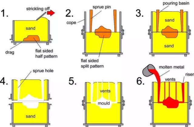
Photo WeChat_20240129101210.jpg

Technical characteristics:

1) Suitable for manufacturing blanks of complex shapes, especially those with complex internal cavities;

2) Wide adaptability and low cost;

3) For some materials with low plasticity, such as cast iron, sand casting is the only forming process for manufacturing parts or blanks.

Application: Castings such as cylinder blocks, cylinder heads and crankshafts of automobile engines.

(2) Investment casting

Investment casting: generally refers to making a model from a fusible material, covering the surface of the model with several layers of refractory materials to form a mold shell, then melting the model and extruding the mold shell, thus obtaining a mold without separation surfaces. , which is then grilled at high temperature. Then the casting plane can be filled with sand. Often called “lost wax casting”.

Process flow:
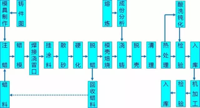
Photo WeChat_20240129101213.jpg

advantage:

1) High dimensional accuracy and geometric accuracy;

2) High surface roughness;

3) It can cast castings of complex shapes, and the casting alloys are not limited.

Disadvantages: The process is complicated and the cost is high.

Application: Suitable for the production of small parts with complex shapes, high precision requirements and difficult to process by other processes, such as turbine engine blades, etc.

(3) Die casting

Die Casting: It uses high pressure to press molten metal into a precision metal mold cavity at high speed. The molten metal cools and solidifies under pressure to form a casting.

Process flow:
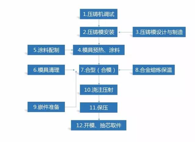
Photo WeChat_20240129101216.jpg

advantage:

1) During die casting, the metal liquid bears high pressure and has rapid flow;

2) The product has good quality, stable dimensions and good interchangeability;

3) High production efficiency and frequent use of die casting molds;

4) Suitable for mass production and good economic benefits.

default:

1) Castings are prone to small pores and shrinkage;

2) Die casting parts have low plasticity and are not suitable for working under impact loads and vibration;

3) When die casting high melting point alloys, the mold life is low, which affects the expansion of die casting production.

Application: Die castings were first used in the automobile industry and instrument industry, and then gradually expanded to various industries, such as agricultural machinery, machine tool industry, electronics industry, the national defense industry, computers, medical equipment, clocks, cameras and everyday life. material. .

(4) Low pressure casting
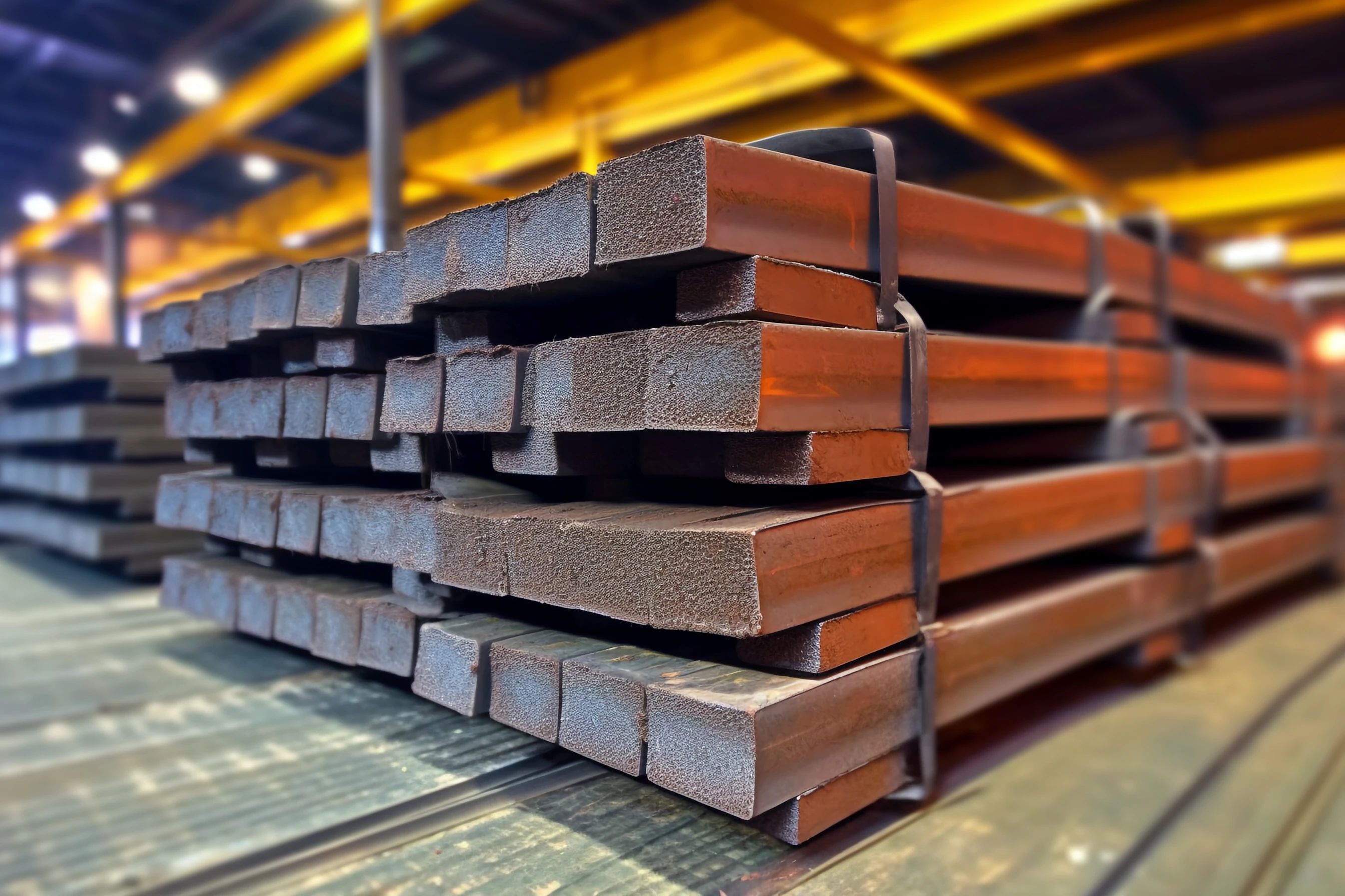
1706494576333912.jpg

Low pressure casting: refers to a method in which liquid metal fills the mold under low pressure (0.02 ~ 0.06 MPa) and crystallizes under the pressure to form a casting.

Process flow:
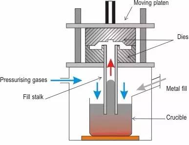
Photo WeChat_20240129101222.jpg

Technical characteristics:

1) The pressure and speed during casting can be adjusted, so it can be applied to various casting molds (such as metal molds, sand molds, etc.), casting various alloys and castings of different sizes;

2) Through bottom injection mold filling, the molten metal is filled smoothly without splashing, which can avoid gas inclusion and erosion of the mold wall and core and improve the qualification rate molded parts;

3) The casting crystallizes under pressure. The structure of the casting is dense, the outline is clear, the surface is smooth, and the mechanical properties are high, which is especially beneficial for the casting of large and thin-walled parts;

4) The feed riser is omitted and the metal utilization rate is increased to 90-98%;

5) Low labor intensity, good working conditions, simple equipment and easy to achieve mechanization and automation.

Application: Mainly traditional products (cylinder heads, wheel hubs, cylinder frames, etc.).

(5) Centrifugal casting

Centrifugal casting: It is a casting method that pours molten metal into a rotating mold, fills the mold under the action of centrifugal force, and solidifies.

Process flow:
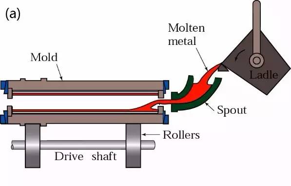
Photo WeChat_20240129101230.jpg

Photo WeChat_20240129101233.jpg

advantage:

1) There is almost no metal consumption in the door system and riser system, thereby improving the process efficiency;

2) No core is needed when producing hollow castings, so the metal filling capacity can be greatly improved when producing long tubular castings;

3) The casting has high density, few defects such as pores and slag inclusions, and high mechanical properties;

4) It is convenient to manufacture composite metal castings of cylinders and sleeves.

default:

1) There are some limitations when used to produce special-shaped castings;

2) The inner hole diameter of the casting part is inaccurate, the inner hole surface is rough, the quality is poor, and the machining allowance is large;

3) Castings are subject to specific gravity segregation.

application:

Centrifugal casting technology was first used in the metallurgy, mining, transportation, drainage and irrigation machinery, aviation, national defense and automobile industries, in at home and abroad, to produce castings in steel, iron and non-ferrous carbon alloys. . Among them, the production of castings such as centrifugal cast iron pipes, cylinder liners and internal combustion engine rings is the most common.

(6) Gravity die casting

Metal Mold Casting: Refers to a forming method in which liquid metal fills a metal mold under the action of gravity and cools and solidifies in the mold to obtain a casting.

Process flow:
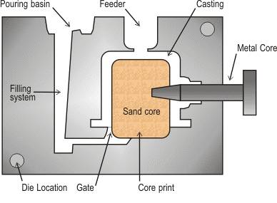
Photo WeChat_20240129101236.jpg

advantage:

1) The metal mold has high thermal conductivity and heat capacity, rapid cooling rate, dense casting structure and mechanical properties which are about 15% higher than those of sand castings;

2) Castings with higher dimensional accuracy and lower surface roughness values ​​can be obtained, and the quality stability is good;

3) Because sand cores are not used or rarely used, the environment is improved, dust and harmful gases are reduced, and labor intensity is reduced.

default:

1) The metal mold itself is not breathable, and certain measures must be taken to exhaust the air from the mold cavity and the gas generated by the sand core;

2) The metal mold has no give and cracks are likely to occur when the casting solidifies;

3) The manufacturing cycle of metal types is long and the cost is high. Therefore, good economic effects can only be demonstrated when mass production is carried out in batches.

application:

Metal mold casting is not only suitable for the mass production of complex-shaped non-ferrous alloy castings such as aluminum alloys and magnesium alloys, but also suitable for the production of metal castings and ingots in iron and steel.

(7) Vacuum casting
1706494694158240.jpg

Vacuum Casting: An advanced die casting process that eliminates or significantly reduces pores and dissolved gases in die casting parts by removing gas from the die casting mold cavity during the die casting process, improving thus the mechanical properties and the surface. quality of die casting parts.

Process flow:
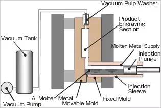
Photo WeChat_20240129101242.jpg

advantage:

1) Eliminate or reduce pores inside die casting parts, improve the mechanical properties and surface quality of die casting parts, and improve plating performance;

2) Reduce the back pressure of the mold cavity, use lower specific pressure and alloys with poor casting performance, and it is possible to pressure cast larger castings with small machines;

3) Filling conditions are improved and thinner castings can be die cast.

default:

1) The mold sealing structure is complex and difficult to manufacture and install, so the cost is high;

2) If the vacuum casting method is not properly controlled, the effect will not be very significant.

(8) Pressing die casting

1706494743800087.jpg

Compression casting: It is a method of solidifying and creeping liquid or semi-solid metal under high pressure to directly obtain parts or blanks. It has the advantages of high utilization rate of liquid metal, simplified process and stable quality. It is an energy-saving metal forming technology with potential application prospects.

Process flow:
Photo WeChat_20240129101248.jpg

Direct compression casting: spray coating, alloy casting, mold closing, pressurization, pressure holding, decompression, mold splitting, blank demolding, reset;

Indirect compression casting: spray coating, mold clamping, feeding, mold filling, pressurization, pressure holding, decompression, mold splitting, blank demolding and resetting.

Technical characteristics:

1) It can eliminate internal defects such as pores, shrinkage cavities and shrinkage porosity;

2) Low surface roughness and high dimensional accuracy;

3) It can prevent the occurrence of casting cracks;

4) Facilitate mechanization and automation.

Application: Can be used to produce various types of alloys, such as aluminum alloys, zinc alloys, copper alloys, ductile iron, etc.

(9) Lost Foam Casting

Lost foam casting (also known as true mold casting): Paraffin or foam models similar in size and shape to the casting are linked and combined into model clusters. After being painted with refractory paint and dried, they are buried in dry quartz sand and vibrated. shape. This is a new casting method that vaporizes the model by pressing it down, and the liquid metal occupies the position of the model, then solidifies and cools to form a casting.

Process flow: Pre-foaming → Foaming → Paint dipping → Drying → Shaping → Pouring → Sand drying → Cleaning.
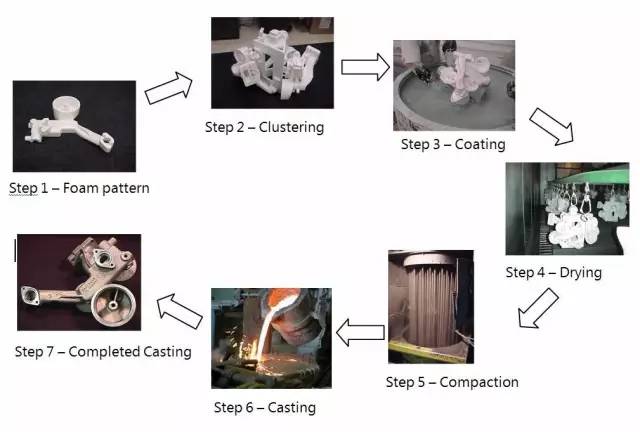
Photo WeChat_20240129101251.jpg

Technical characteristics:

1) The casting has high precision and does not contain sand core, which reduces processing time;

2) No separation surface, flexible design and high degree of freedom;

3) Clean production, no pollution;

4) Reduce investment and production costs.

application:

It is suitable for producing precision casting parts of various sizes with complex structures. There is no limit to the alloy type and production batch. Such as gray cast iron motor housing, high manganese steel elbow, etc.

(10) Continuous casting

Continuous Casting: This is an advanced casting method. Its principle is to continuously pour molten metal into a special metal mold called a crystallizer. The solidified (crusted) castings are poured continuously to the other side of the crystallizer. it can get castings of any length or a specific length.

Process flow:
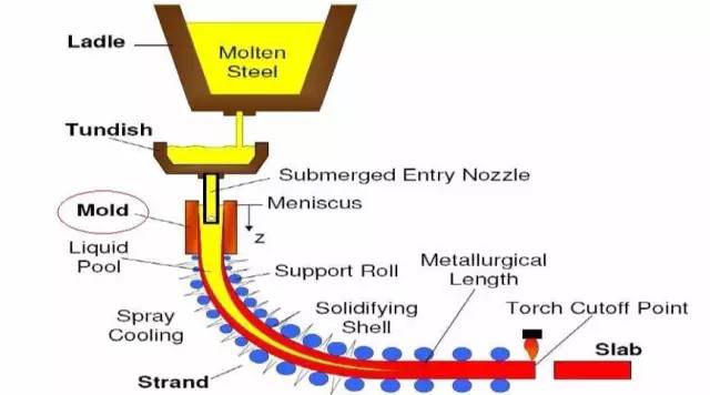
Photo WeChat_20240129101253.jpg

Technical characteristics:

1) Because the metal is cooled quickly, the crystallization is dense, the structure is uniform, and the mechanical properties are good;

2) Save metal and increase efficiency;

3) The process is simplified and shaping and other processes are eliminated, thereby reducing labor intensity, the required production area is also greatly reduced;

4) Continuous casting production is easy to mechanize and automate, thereby improving production efficiency.

application:

The continuous casting method can be used to cast steel, iron, copper alloys, aluminum alloys, magnesium alloys and other long castings with constant section shapes, such as ingots, slabs, bar blanks and pipes.


2. Plastic forming

Plastic forming: A process that uses the plasticity of materials to process parts with little or no cutting under the action of external forces from tools and molds. There are many types, including forging, rolling, extrusion, stamping and stamping.

(1) Forging
1706494836850057.jpg

Forging: This is a processing method that uses forging machines to exert pressure on metal blanks to cause plastic deformation to obtain forgings with certain mechanical properties, shapes and sizes.

According to the forming mechanism, forging can be divided into free forging, die forging, ring rolling and special forging.

Free Forging: This is generally a processing method that uses simple tools to hammer ingots or blocks of metal into the required shape and size on a forged hammer or hydraulic press.

Forging: It is formed using a die on a stamping hammer or hot stamping press.

Ring rolling: refers to the production of ring-shaped parts of different diameters by means of special equipment ring rolling machines. It is also used to produce wheel-shaped parts such as automobile hubs and train wheels.

Special forging: including forging methods such as roll forging, cross wedge rolling, radial forging and liquid pressure forging. These methods are more suitable for producing parts with certain special shapes.
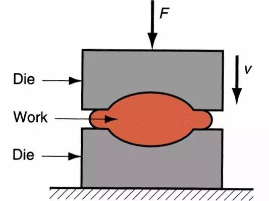
Photo WeChat_20240129101259.jpg

Process flow: forging blank heating → forging preparation → stamping → trimming → punching → correction → intermediate inspection → heat treatment of forging → cleaning → correction → inspection.

Technical characteristics:

1) Forgings are of higher quality than castings and can withstand significant impact forces. Their plasticity, toughness and other mechanical properties are also superior to those of cast parts and even superior to those of rolled parts;

2) Save raw materials and shorten processing hours;

3) Examples of high production efficiency;

4) Free forging is suitable for single-piece and small batch production and provides greater flexibility.

application:

Herringbone rollers and gears of large steel rolling mills, rotors, wheels and retaining rings of steam turbine generators, huge cylinders and working columns of hydraulic presses, axles of locomotives, crankshafts and connecting rods of automobiles and tractors, etc. .

(2) Rolling
1706494890958165.jpg

Rolling: A method of pressure processing in which the metal blank passes through the gap between a pair of rotating rollers (of different shapes) and is compressed and formed by the rollers. Rolling reduces the cross section of the material and increases the length.

Classification of rolling: According to the movement of the rolled part, it is divided into: longitudinal rolling, transverse rolling and transverse rolling.

Longitudinal rolling: It is a process in which the metal passes between two rollers rotating in opposite directions and produces plastic deformation during them.

Cross rolling: The direction of movement of the rolled part after deformation is consistent with the direction of the roller axis.

Cross rolling: the rolled part moves in a spiral, and the rolled part and the roller axis form a non-specific angle.
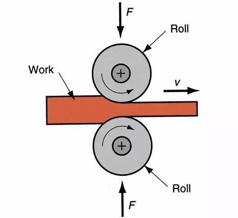
Photo WeChat_20240129101305.jpg

application:

Mainly used in profiles, plates, pipes, etc. in metallic materials, as well as in some non-metallic materials such as plastic products and glass products.

(3) Extrusion
1706494930962808.jpg

Extrusion: under the action of unequal compressive stress in three directions, the blank is extruded from the mold hole or space to reduce the cross section and increase the length, and the processing method to become the desired product is called extrusion. This processing of the blank is called extrusion.

Process flow:

Preparation before extrusion → heating of cast rod → extrusion → drawing, twisting and straightening → sawing (to length) → sampling and inspection → manual aging → packaging and storage.
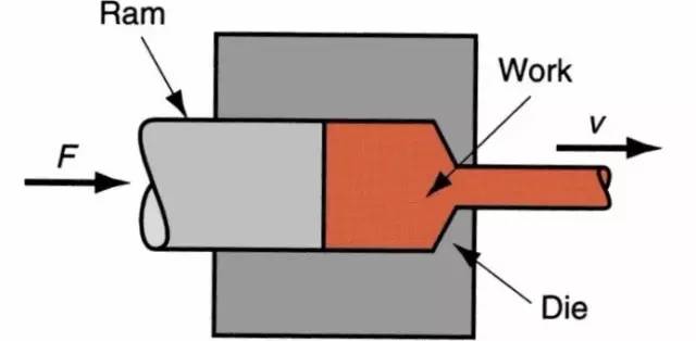
Photo WeChat_20240129101316.jpg

advantage:

1) Wide production range, numerous product specifications and varieties;

2) High production flexibility, suitable for small batch production;

3) The product has high dimensional accuracy and good surface quality;

4) The equipment investment is small, the factory area is small, and it is easy to realize automated production.

default:

1) Large loss of geometric waste;

2) Uneven metal flow;

3) The extrusion speed is low and the auxiliary time is long;

4) Tool loss is large and the cost is high.

Production scope: mainly used for manufacturing long rods, deep holes, thin walls and special-shaped cross-section parts.

(4) Drawing

Drawing: A plastic processing method that uses external force to act on the front end of the metal to be drawn to pull the metal blank from the die hole smaller than the cross section of the blank to obtain products with shape and of corresponding size.
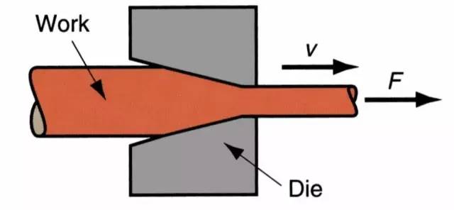
Photo WeChat_20240129101319.jpg

advantage:

1) Accurate size and smooth surface;

2) Tools and equipment are simple;

3) Continuously produce long products with small cross section at high speed.

default:

1) The amount of deformation of each pass and the total amount of deformation between two anneals are limited;

2) Length is limited.

Production scope: Drawing is the main processing method of metal pipes, bars, profiles and wires.

(5) Stamping
1706495001952991.jpg

Stamping: It is a forming processing method that relies on presses and molds to apply external force to plates, strips, pipes and profiles to cause plasticity, deformation or separation, thus obtaining parts (stamping parts) of the required shape and size.
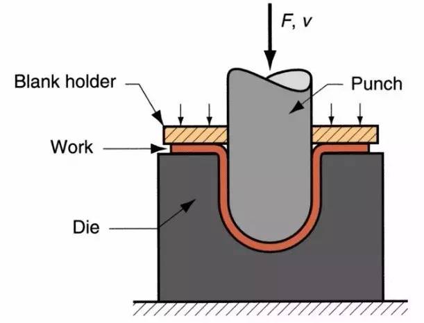
Photo WeChat_20240129101325.jpg

Technical characteristics:

1) Lightweight and high rigidity products can be obtained;

2) Good productivity, suitable for mass production and low cost;

3) Products of uniform quality can be obtained;

4) High material utilization, good shear and recyclability.

Scope of application:

60-70% of the world’s steel products are sheet metal, most of which is stamped to form finished products. The body, chassis, fuel tank, radiator fins of automobiles, boiler drums, container housings and silicon steel sheets of engines and electrical appliances are all stamped. There are also a large number of stamped parts in products such as instruments and meters, household appliances, bicycles, office machines and living utensils.


3. Machining

1706495046732889.jpg

Machining: During the production process of parts, a tool is used to directly cut off the excessive thickness of the metal layer on the blank to make it conform to technical requirements such as dimensional accuracy, shape accuracy and shape accuracy. position, as well as the surface quality required by the design.

Commonly used machining methods:
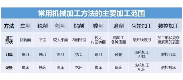
Photo WeChat_20240129101333.jpg


4. Welding

1706495139677343.jpg

Welding: Also known as soldering, welding is a manufacturing process and technology that uses heat, high temperature, or high pressure to join metal or other thermoplastic materials such as plastics.

Welding classification:
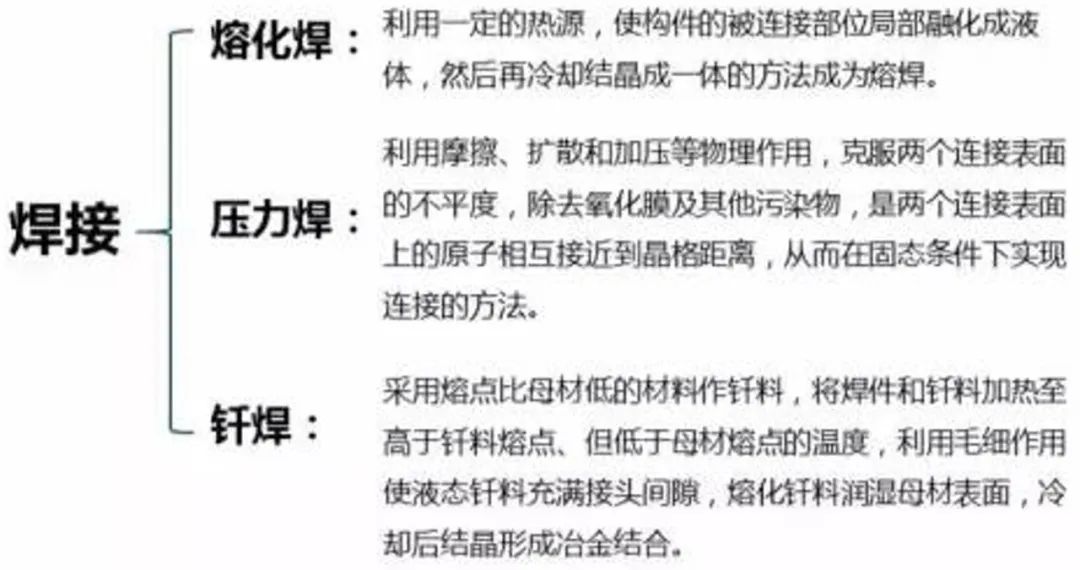
Photo WeChat_20240129102447.jpg

Photo WeChat_20240129102450.jpg


5. Powder metallurgy

Powder metallurgy: It is a processing technology that prepares metal or uses metal powder (or a mixture of metal powder and non-metallic powder) as raw material, and makes metal materials, composite materials and various types of products by shaping and sintering.

Basic process flow:
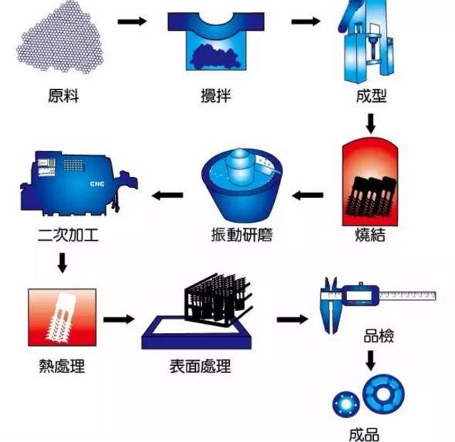
Photo WeChat_20240129102453.jpg

advantage:

1) Most refractory metals and their compounds, false alloys and porous materials can only be manufactured using powder metallurgy methods;

2) Save metal and reduce product costs;

3) It will not cause any pollution to the materials and it is possible to produce high purity materials;

4) Powder metallurgy can guarantee the accuracy and uniformity of material composition ratio;

5) Powder metallurgy is suitable for producing products of the same shape in large quantities and can significantly reduce production costs.

default:

1) Consider part size when there is no batch size;

2) The cost of molds is relatively higher than that of casting molds.

Production scope:

Powder metallurgy technology can directly manufacture porous, semi-dense or fully dense materials and products, such as oil-impregnated bearings, gears, cams, guide rods and cutting tools.


6. Metal injection molding

1706495294412373.jpg

MIM (Metal injection Molding): is the abbreviation of metal injection molding. This is a molding process in which a plasticized mixture of metal powder and its binder is injected into the mold. This involves first mixing the selected powder with a binder, then granulating the mixture and then injection molding it into the desired shape.

MIM process flow:

The MIM process is divided into four unique processing steps (mixing, forming, degreasing and sintering) to achieve part production and determine whether surface treatment is required based on product characteristics.
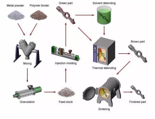
Photo WeChat_20240129102458.jpg

Technical characteristics:

1) Unique forming parts;

2) The surface quality of parts is good, the scrap rate is low, the production efficiency is high, and it is easy to realize automation;

3) Low requirements for casting materials.

Technical core:

The binder is at the heart of MIM technology. Only by adding a certain amount of binder can the powder have improved fluidity to be suitable for injection molding and maintain the basic shape of the compact.


7. Semi-solid forming of metal

Semi-Solid Forming: Use the unique rheology and melting properties of non-dendritic semi-solid metals (semi-solid metals, called SSM) to control the quality of castings.

Semi-solid forming can be divided into flow forming and thixoforming.

(1) Rheoforming
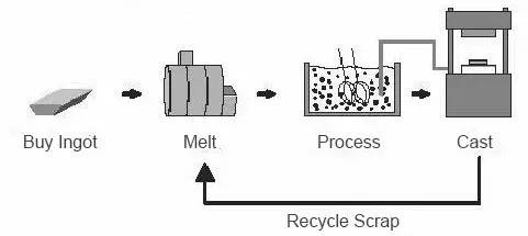
Photo WeChat_20240129102501.jpg

(2) Thixoforming

Photo WeChat_20240129102504.jpg

Technical characteristics:

1) Reduce liquid formation defects and significantly improve quality and reliability;

2) The forming temperature is lower than the forming temperature of the full liquid, which greatly reduces the thermal impact on the mold;

3) It can produce alloys impossible to produce by conventional liquid forming methods.

application:

It has been successfully used in the manufacture of master cylinders, steering system parts, rocker arms, engine pistons, wheel hubs, transmission system parts, fuel system parts and parts air conditioning, etc. in aviation, electronics and consumer goods.


8. 3D printing

3D Printing: This is a type of rapid prototyping technology. This is a technology that uses bondable materials such as metal powder or plastic to build objects by printing layer by layer based on digital model files.

Comparison of 3D printing technologies:
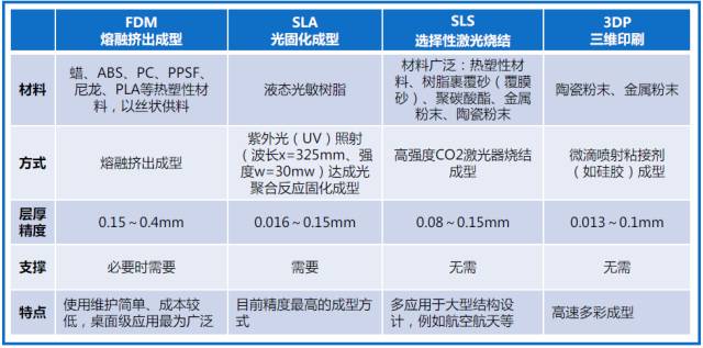
Photo WeChat_20240129102510.jpg


Daguang focuses on providing solutions such as precision CNC machining services (3-axis, 4-axis, 5-axis machining), CNC milling, 3D printing and rapid prototyping services.

Photo WeChat_20240129151501.jpg

CNC Knowledge: Analysis and solutions to the difficulties of processing large thin-walled boxes

1 Preface

In the transmission system of engineering machinery, the box body serves as the basis for various transmission shafts and requires high processing precision. Boxes generally have the characteristics of large volume, thin walls, many holes and complex internal cavities. They are prone to deformation during processing, and processing accuracy is difficult to guarantee. Due to the large volume of the box, the same hole system distributed on both end faces requires a rotating machine tool table to drill the inner holes at both ends, so the equipment requirements of processing are higher in terms of clamping deformation of thin walls; Parts will result in changes to the processed parts. The position of each pinhole and hole changes, which ultimately leads to the position of each hole system being out of tolerance.

By analyzing the box processing technology and structure, measuring the accuracy of processing equipment, formulating corresponding clamping plans and reasonable processing procedures, we can solve the difficult problems encountered during processing and ensure the precision of box processing.

2 Analysis of processing difficulties

The box material shown in Figure 1 is QT450-10 ductile iron. After the box is cast, preliminary rough machining is carried out. After rough machining, a machining allowance of 2 mm is left on one side of the box. The main content of the treatment is 4 planes and each facing system. coaxiality φ0.04 mm. After carrying out process analysis on the box and combining it with the existing processing equipment, it is estimated that there are mainly the following processing difficulties.

(1) Clamping deformation When the box is clamped, slight deformation of the clamping surface and clamping points will cause the position of each hole to change due to rebound deformation after the box is completed and the clamping device tooling removed, which will result in extreme coaxiality. poor.

(2) Deformation during processing: the wall of the box is thin, and the overall structural rigidity of the box is poor. Thermal deformation occurs during processing. Once the clamp is removed, the box undergoes stress release deformation, which also affects everyone’s position. system of holes in the box after treatment.

(3) Equipment origin drift The processing equipment used this time is a horizontal machining center After the worktable is rotated 180°, the origin has an uncorrected drift error within 0.03mm. Since the box is large, the interior holes on both ends need to be drilled. Therefore, the rotation accuracy of the workbench seriously affects the machining accuracy of the box, resulting in non-concentricity of each hole system after processing and coaxiality. out of tolerance.

Figure 1 Box

3 solutions

Several process tests were carried out to resolve the above processing difficulties and the following solutions were determined.

1) Check the flatness of the clamping surface of the box. The pressure point should be a solid point, which can reduce the clamping deformation of the box.[1]. As shown in Figure 1, the bottom surface serves as the processing reference surface of the box and is adjusted inside the box due to the influence of flatness, clamping deformation occurs. You can use dial indicators to measure the left and right ends of the box and read the percentage values ​​twice before and after compressing the box to detect the pressure when tightening and loosening the box. In order to ensure the accuracy of the box after processing, it is necessary to ensure that the deformation of the pressure fitting at both ends is less than 0.01mm. If the deformation exceeds 0.01 mm, copper pads can be used at the pressure fitting. point and between the joint surface of the box and the tooling. Ensure that the deformation of the box press fit is less than 0.01mm, thereby reducing the processing deformation caused by clamping deformation.

2) Processing by separate methods of semi-finishing and finishing[2]reduce deformation under processing stress. When the material is removed during box processing, a large amount of heat will be carried away with the chips, but some heat will still be absorbed by the box. Due to uneven heat, the box will undergo thermal deformation and machining errors will be caused. by thermal deformation account for a large proportion of the total machining errors, seriously affecting the processing accuracy.[3]. During semi-finishing, the cutting quantity is large, the cabinet is heated and deformed, and the stress generated by cutting the cabinet is large. Through process optimization, the cabinet is divided into semi-finishing and finishing methods. cabinet, the components produced during processing are removed from thermal deformation stress relief. When finishing, the cutting amount is only about 0.15mm, and less heat is generated, so the box deformation is basically within 0.01mm, which is lies within the allowable range of processing accuracy of the box. When machining sequentially, since the finishing allowance is small, the process positioning holes can be added to ensure that the marks of the two machining operations are consistent and avoid the problem of insufficient allowance during finishing.

3) Using a dial gauge for alignment, use the coordinates to process the other end hole to ensure the holes at both ends are coaxial. Since the size of the drift of the center of rotation of the workbench of this equipment is uncertain, it is necessary to correct the center of rotation of the workbench each time a box is processed.[4]. The φ600H7 hole and the φ250H7 hole at the left end of the box are processed one by one. The coaxiality of the two holes is guaranteed by the precision of the machine tool itself. Once the two holes on the left end have been processed, the box is processed. rotated 180° and a dial indicator is used to align the φ250H7 hole that has been completed, use the center of the hole as the origin to process the φ500H7 hole and the φ600H7 hole at the right end. By aligning the coordinates of the machined holes in the cabinet, the impact of the original drift on the processing accuracy of the cabinet after the equipment is rotated is eliminated.

4 Conclusion

When the machining accuracy of the box is out of tolerance, especially when the geometric tolerance is out of tolerance during processing, we must first determine the cause by analysis, and then formulate solutions based on the corresponding reasons for the out of tolerance and find a solution. suitable solution. This article analyzes the difficulties of box processing, comprehensively solves the existing problems in the box processing process from the perspectives of processing methods, equipment precision and clamping methods, improves quality of box processing and meets the technical requirements of the drawings. .

Daguang focuses on providing solutions such as precision CNC machining services (3-axis, 4-axis, 5-axis machining), CNC milling, 3D printing and rapid prototyping services.

Image WeChat_20240130103711.png

CNC Knowledge: Machining technology for thin-walled aluminum alloy parts with high precision and complex shapes

1.Preface

Aluminum alloy thin frame structural parts have the characteristics of light weight, pressure resistance and corrosion resistance, and are widely used in aerospace spare parts.[1-3]in order to achieve the goal of reducing the overall quality of the aircraft model and improving flight performance. However, due to the large size of structural parts and high requirements for surface quality, the cutting force and clamping force during machining will form residual stresses in the material, which will lead to changes in the size of the parts.[4-7]it is difficult to meet the requirements for product characteristics. Current existing processing methods require the use of high-end and high-precision equipment to reduce the amount of cutting and perform multiple passes.[8-10]low processing efficiency and high production cost. This article takes a high-precision aluminum alloy thin-walled part with a complex shape for aerospace as an example. Depending on the size of the workpiece, a blank with a chuck is designed and a reasonable process is used for efficient completion. cold working, heat treatment and wire cutting. Arrange to avoid dimensional changes caused by stress in thin-walled parts and control the extent of processing deformation.

2. Processing difficulties

Thin-walled parts are made of high-strength 2D14 cemented carbide. The overall volume is relatively large and the walls are thin. The requirements for dimensional accuracy and geometric tolerances are high. The workpiece milling process mainly involves cavity milling and contour milling. Parts are fixed using pressure plates, combination fixtures and machine tool worktables. After the parts are processed, the stress release caused by the tightening of pressure plates and other fasteners. will cause dimensional deviations. The size of the final processed thin-walled parts changes and cannot meet the characteristic high-precision requirements of aerospace parts.

3. Process Layout

3.1 Overall process path

According to the appearance characteristics and processing difficulties of the parts, the process sequence is reasonably organized, which involves the use of knowledge and equipment related to cold processing, electrical processing and heat treatment. The overall process layout is shown in Figure 1, and the shape and structure of the parts are shown in Figure 2.

Figure 1 Overall process layout

Image WeChat_20240130103716.png

Figure 2 Appearance and structure of the part

According to the appearance characteristics of thin-walled aluminum alloy parts, when cutting, leave a 30-50mm chuck at each of the left and right ends. The chucks at both ends are tightened and fixed, as well as a two-edged φ16. A φ20mm carbide tool is used to roughen the blank. It is 6000 to 7000 rpm, leaving a margin of 3 to 5 mm on one side. After rough machining, the parts are subjected to the first stabilization and aging treatment, and then a φ10~φ16mm three-edged carbide tool is used to semi-finish the parts. The mandrels at both ends are tightened to correct the shape and interior cavity. , leaving 0.5 on one side. The semi-finished parts undergo a second stabilization aging treatment, then the clamps at both ends are clamped by pressure plates, and φ6~φ8mm three-edged carbide tools are used to finish the parts, and the Outer shape and inner cavity size of the parts are processed and formed. After the processing of the cavity and contour of the workpiece is completed, wire EDM is used to remove the mandrels at both ends, because there are traces of wire cutting removal on thin-walled workpieces and the chuck after wire EDM, to ensure proper operation. integrity of the overall surface quality of thin-walled parts, use fine sandpaper to polish the wire cutting chuck of the workpiece. Use tools of different diameters during rough machining, semi-finishing and finishing. Double-edged tools can quickly remove material, and three-edged tools can refine the surface quality to ensure that there are no traces on the milled surface of the workpiece. at the same time, two heat treatments can reduce cold treatment. To release the stress of the material during machining, the non-contact wire EDM processing method can effectively avoid the dimensional changes caused by the residual stress of the material during machining and the elastic deformation of the material during clamping.

3.2 Heat treatment

The implementation of an aging stabilization treatment is crucial. For the first stabilization aging, the roughly machined part is placed in an artificial aging furnace, heated to 250-290°C, kept for 2-4 hours and then cooled in air. For the second stabilization aging, the semi-finished part is placed in an artificial aging oven, heated to 250-290°C, kept for 1-2 hours, and the parts are subjected to thermal cycling. The thermal cycle treatment step for aluminum alloys consists of placing the parts in a low temperature container between -70 and -50°C for 1 to 2 hours. In order to improve the effect of thermal cycle treatment, it can be cooled in liquid nitrogen. The cooling rate of cold processing does not have a substantial impact on thermal cycling processing. Once the cold treatment of the product is completed, take it out of the container at low temperature. After the formed frost melts, place it in the heating equipment to heat it to the specified temperature, or dry it first at about 50°C for 1 hour. at 2 o’clock. If the room cannot be heated immediately after drying due to working conditions, an interruption of up to 20 hours is allowed. After the parts are heated and kept warm, they are cooled to room temperature and then placed in a low temperature container. Here, the number of cycles should be selected based on the processing requirements of the part.

3.3 Cold working

When CNC milling thin-walled aluminum alloy parts, in order to avoid deformation, the processing process is divided into three stages: rough machining, semi-finishing and finishing. When rough machining, the tool speed is 6000-7000 rpm. The high speed can effectively remove material, form the overall contour of the workpiece in a short time, and improve processing efficiency. At the same time, a margin of 3 to. 5 mm is left on one side of the part for semi-finishing; During semi-finishing, the tool speed is controlled between 2000 and 2500 rpm. Low speeds can be effectively maintained. It can check the surface roughness of parts after processing, and at the same time, the processed tool marks can be thinned to further improve the surface quality of parts, and control to leave a margin of 0.5-1mm on one side for finishing. During finishing, the tool should be reduced appropriately. Rotation speed, control the tool speed at 1500 ~ 1800 rpm, remove excess and ensure surface quality.

3.4 Electrical machining

After the cavity and contour processing of aluminum alloy thin-walled parts is completed, the processing chucks are left at both ends of the parts to avoid the stress on the thin-walled parts caused by the removal of the parts. chucks from the cold. working machine and resulting in product deformation, wire EDM technology is used. Wire EDM machining is non-contact EDM machining. There is no significant cutting force between the tool electrode and the workpiece, and no error will occur due to mechanical deformation. According to the properties of the aluminum alloy, the positive polarity processing method is adopted (the workpiece is connected to the positive electrode and the electrode wire is connected to the negative electrode, the processing current is selected between 3 and 5 A, the pulse). the width is selected between 30 and 50 μs and the duty cycle is 1:7 to 1:5.

The joint between the workpiece and the chuck after wire EDM processing is polished with fine sandpaper to ensure the overall surface integrity of thin-walled parts and ensure that the parts as a whole meet the requirements of high precision and high aerospace performance.

4.Conclusion

Based on the difficult-to-machine characteristics of aluminum alloy materials, this article optimizes the process of high-precision thin-walled parts with complex shapes. Through the reasonable arrangement of cold processing, heat treatment and electric machining, and the selection of different tools and processing methods according to rough machining, semi-finishing and finishing methods, the quality of Parts and processing efficiency are effectively guaranteed, and we get rid of the conventional thinking of relying on high-end machine tools. It has been verified by actual processing that the overall layout of the process route is reasonable and the process layout is scientific and compact, which not only avoids changes in the machining dimensions of parts, but also reduces the parts turnover time and improves production efficiency. .

Expert commentary

The article takes high-precision aluminum alloy thin-walled parts with complex shapes as an example. According to the shape and size of parts, it focuses on optimizing cutting methods and clamping methods by adding blank chucks and adopting reasonable process routes. heat treatment, cold treatment and wire cutting are organized efficiently. In other processes, appropriate tools and processing methods are selected to avoid dimensional changes caused by the processing stress of thin-walled parts, and the experience accumulated in controlling the deformation of these parts.

The highlight of the article is to change ideas, find new paths, break conventional thinking and bypass technical bottlenecks. Through reasonable process arrangements, we can gradually solve the processing difficulties and get rid of the dependence on high-end machine tools in the processing of high-precision aluminum alloy thin-walled parts. Depending on the shape characteristics of the parts, we will apply them globally. the knowledge related to heat treatment, cold treatment and electrical machining, and through the overall layout and process improvements, have solved the problem of processing deformation of complex parts.

Daguang focuses on providing solutions such as precision CNC machining services (3-axis, 4-axis, 5-axis machining), CNC milling, 3D printing and rapid prototyping services.

CNC Knowledge: Sharpening strawberries, technology is money!

The cutting edge on the surface of the round shank of the tungsten steel milling cutter is the primary cutting edge, and the cutting edge on the end surface does not pass through the center and is the secondary cutting edge. The workpiece is not suitable for axial feed movement. Before sharpening, the grinding wheel should be inspected. In case of run-out, irregular cylindrical surface, excessive fillet, etc., it must be trimmed. Generally, the cylindrical surface of the grinding wheel can be dressed with a wheel dresser (diamond dresser, gear dresser, etc.), or a used grinding wheel with relatively large abrasive grain hardness can be used for dressing. If the side surface of the grinding wheel is uneven, the grinding wheel can be replaced.

Tungsten Steel Milling Cutter End Face Grinding Technology

Regardless of the number of blades in a tungsten steel milling cutter, the end face of the blade must first be ground flat perpendicular to the axis. This is key to ensuring that the highest point of the blade is on the same plane. The methods for grinding the blade end and checking the verticality of the cutter axis are as follows:

(1) Visual inspection. Using a flat plate, place the tungsten steel cutter blade down on the flat plate and observe the left and right tilt angles. Then rotate the cutter 180° and observe its left and right tilt angle. In the same direction, if the inclination angles observed twice are different, grinding is necessary until the inclination angles observed twice in the same direction are the same. Then rotate the cutter 90°, repeat the above action and check the other direction.

(2) Use a square ruler to correct. Calibrate with a 90° square ruler on a flat plate. Place the cutter and square ruler flat and observe whether there is a gap between the cutter and the square ruler or whether the gap is uniform. Then judge the verticality of the milling. cutter according to the gap and correct the cutter. The knife is sharp.

(3) Self-correction. Fix the tungsten steel cutter on the chuck of the drill or milling machine, place a scrap grinding wheel underneath, select the appropriate rotation speed, turn on the machine tool, then move the cutter down, grind on the grinding wheel, and grind according to the grinding situation of the end face.

(4) Place the heavily chipped tungsten steel cutter on the cutting machine. After adjustment, cut the cutter section in one go.

(5) Grind the tool on the cutter and clamp it with a three-jaw or tapered sleeve. After adjustment, use a grinding wheel to grind the end face of the cutter until it meets the requirements.

Cross-flute technology for tungsten steel cutters

If there is no circular groove on the front of the end face of the four-blade tungsten steel cutter, you need to use the grinding wheel thread or use a grinding wheel cutting machine to reopen the transverse groove in the direction of the transverse spiral groove of the cutter, with a depth of about 1-2mm (too deep is easy to crack, too shallow is easy to grind the secondary back corner). When grooving, make sure that the side of the grinding wheel does not touch the other cutting edge below (Note: This cross groove has a chip evacuation function. If it is not open, the angle of inclination of the recessed edge in the middle should be increased).

Tungsten Steel Milling Cutter End Face Point Sharpening Technology

(1) When sharpening each blade surface separately, use the tip of each blade as a reference and keep the tip of the blade as a principle, then grind the cutting angle (no need to grind if it is not is no chipping), clearance angle and secondary clearance angle (if a large cutting volume requires better strength, it is recommended to increase the edge corner angle) and tilt angle of the edge in front of the tool sharpening.

(2) Relevant angle selections are draft angle 6° to 8° (secondary draft angle 30° to 45°) and edge tilt angle 1° to 3°. The choice of draft angle depends on the hardness of the part. The greater the hardness of the material, the smaller the angle. The principle of selecting the blade tilt angle is that the four blades should be concave towards the middle and. the middle of the blade should not be convex, otherwise the milled plane will definitely be uneven, and the more concave the middle of the blade, the better. In fact, the four blades are concave towards the middle. the better the roughness accuracy. At this point, the deeper the processing depth (e.g. greater than 2mm but within the allowable range), the better the roughness accuracy, as the entire cutting edge will participate in the cutting and the resulting surface quality will be best.

(3) After sharpening, place the tungsten steel cutter on a platform. If the axis is vertical, all the tips of the blade can be aligned and the angle of deviation of the blade can be evenly centered, so that it can meet. the requirements. At this time, you can also use a 90° square ruler on a flat plate to correct it. After laying it flat, observe whether there is a gap or whether the gap is uniform between the cutter and the square ruler. Generally, look at the two relatively high feet first (the two feet that touch the bottom first). If they are not vertical, grind the taller legs until the two opposite legs are the same height (i.e. vertical at that point). feet If there is a difference in height between the two opposite feet, the cutter will oscillate. At this time, lower both upper feet at the same time. Likewise, rotate the cutter 90° to observe the verticality of the other two opposite legs, and finally make all four legs touch the bottom at the same time and make the cutter vertical. Milling cutter after sharpening.

In manual sharpening, it is not easy to grasp the height and angle of the blade. This varies from person to person when training. Just be careful to sharpen the back angle a little, but it should be concave in the middle. , even if the cutting edge is uneven, as long as the cutting edge simply holds the tip at the highest point, which can also ensure that the sharpened tool can be milled normally. In addition, if it is not necessary to clean the internal cavity, you can also grind the chamfer more than 0.2mm at the tool tip to increase the strength of the tool tip .

Sharpening technology of the main edge of the tungsten steel cutter (i.e. the side edge)

If the main edge of the tungsten steel cutter is worn, it should be ground along the spiral line on the grinding wheel (smaller grinding wheel diameter is better) (it is difficult for beginners to grind it well) . However, there is usually a taper after grinding. The smaller the taper, the higher the operating level.

Daguang focuses on providing solutions such as precision CNC machining services (3-axis, 4-axis, 5-axis machining), CNC milling, 3D printing and rapid prototyping services.

Image WeChat_20240131093449.png

CNC Knowledge: New method for measuring dimensions of CNC machined housing parts

Regarding the angle, arc and spatial dimensions of CNC machined housing parts, the advantages and disadvantages of various measurement methods are presented, and the measurement accuracy is considered between simple prototypes, die-casting machines and measure three-dimensional, optical projection measurements or a profiler. measurement methods. In order to improve efficiency and economy, a new measurement method based on traditional test samples and modified measurement tools was selected to improve efficiency and reduce costs while maintaining measurement accuracy, and provide a theoretical basis for lightweight measurement.

1 Preface

In actual production and processing, the angular dimensions, arc dimensions, circle centers and spatial dimensions of some parts are difficult to measure accurately by simple methods if operators and quality inspectors only use traditional hard tools for dimensional inspection. accuracy often cannot meet the design requirements.[1]. In the modern manufacturing industry, the advantages of using CNC machine tools to process complex surfaces such as cones and arcuate surfaces are obvious. The dimensional accuracy and shape accuracy of the processed parts are much higher than that of ordinary machine tools. In actual production, both precision and fineness of measurements must be taken into account. Production progress cannot be limited due to detection methods, which place higher demands on measurement methods. If high-precision measuring instruments are used to facilitate measurement, such as profilometers, coordinate measuring machines, optical image measuring instruments or CT industrial measuring machines, the measurement accuracy can meet the requirements design drawings, but equipment procurement and maintenance costs are very high. The measurement is time-consuming and requires professionals to operate. These practical issues may be difficult for ordinary businesses to accept. If you only use traditional hard tools for measurement, they may not be able to meet the requirements of the design drawing, or it may not be possible to measure at all. In actual production, traditional measuring tools, modified measuring tools, CNC measuring machines and drawing

The effective combination of drawing software can solve most dimensional measurement problems. Aiming at the problems of measuring angle, arc size and spatial size of casing parts, this article proposes a simple measurement method based on traditional inspection models and modified measuring tools, which can not only meet higher measurement accuracy requirements, but also meet the needs of general businesses. Economic requirements.


2 Measurement methods

1) Example of measurement method

Early in part design, to ensure structural integrity, coordination, and strength of parts, designers will add features such as arcs, fillets, and spatial position relationships to parts. Designers often don’t think much about part processing technology and dimensional inspection methods, which adds difficulties to production and manufacturing. In actual production and processing, for fillet and arc detection, sample measurement is generally preferred, also known as R gauge comparative measurement method. This fillet and arc measurement method is very simple and quick, but it also has disadvantages. Since the arc jig can only measure arcs of specific sizes, such as R5mm, R6mm and other fixed sizes, it cannot accurately measure the size of arcs. and the non-standard arc size cannot be accurately measured with the R gauge. Therefore, for some parts with high arc size accuracy requirements, the sample measurement method cannot meet to the requirements. For measuring non-standard arcs, a wire cutting machine can also be used to cut the required arc size on a thin steel plate. After successful measurement and calibration, it can be used as an appearance model for actual partial arc measurement. production. Likewise, angle models can measure certain standard angles. In actual production, lathes often use angle jigs when setting tools. In some cases where the angles and relative positions of certain parts are good, it is more scientific and accurate to use an angle ruler to measure. However, in many real productions, the angle ruler cannot accurately measure internal angles and small angles that interfere with the angle ruler. In this case, an angle gauge should be used in conjunction with a feeler gauge, which can measure most angles.

2) Profile meter measurement method

The profilometer is mainly used to measure the shape and contour of the exterior and interior surfaces of machined parts. It detects the diameter, arc, center distance, chord length and angular dimensions of the inner and outer surfaces of the workpiece through contact sensor probes without damaging the workpiece surface, wait. The profilometer measurement method is that the contact surface profile sensor probe directly contacts the interior and exterior surfaces of the workpiece. Driven by the motor, it slides slowly along the measured surface of the part. During the sliding process, the sensor converts the received profile. information in an electrical signal. The electrical signal is stored in the computer as a digital quantity. The technical measurement software analyzes and processes the data at the same time, the contour information of the measured part is displayed on the computer screen. can be selected for calculation and measurement, including arc radius, chord length and radian, center distance, angle, linear position relationship and distance, etc. The tip radius and nonlinear motion path of the probe can be compensated by the post-processing program to improve the accuracy of workpiece measurement. At the same time, the profiler measurement software can save the measured data and configure the data output and print function. , and can also save the measurement data to hard disk and export it as a document.[2]. The advantages of the profilometer measurement method are mainly reflected in the fact that it can not only directly measure the internal and external contour dimensions of some difficult-to-detect parts, but also directly and accurately represent the internal surface contours and exterior of the room according to a specific standard. The measurement results can be directly output through the software. However, the profilometer measurement method also has certain disadvantages, that is, the measured surface is easily scratched by the probe, which requires high-quality inspection personnel. For closed angles on certain parts, the precision of the curves drawn after measurement is relatively. weak.

3) Measuring method of three-dimensional coordinate measuring machine

At present, as a measuring equipment with high versatility, high degree of automation and high detection accuracy, coordinate measuring machines are widely used in aerospace manufacturing and scientific and technological research. The three-dimensional coordinate measuring machine converts the measurement of each captured geometric element into measurement of the coordinate position of points, lines and sets of these geometric elements through the probe.[3]after measuring the coordinates of each geometric element, the shape, size, angle, relative position in space and other information of these geometric elements are calculated through special engineering software according to rules and standards specific integrated. In terms of measurement principles, all geometric elements of any workpiece can be detected by a three-dimensional coordinate measuring machine, and the coordinate measurement accuracy of a high-precision coordinate measuring machine can reach the level of micron. The advantages of the coordinate measuring machine are obvious, such as accurate, fast and convenient measurement; the disadvantage is that for ordinary enterprises, its use and maintenance costs are very high, resulting in wasted measurement resources.

4) Optical projection measurement method

The detection function of the optical projection measuring machine is similar to that of the profilometer, and the measurement accuracy is slightly lower than that of the profilometer. When measuring, place the measured workpiece horizontally on the measuring machine workbench, illuminate the workpiece with light, and form a difference between the light-transmitting part and the light-shielding part. The built-in program calculates according to the corresponding rules. , and displays the enlarged outline of the measured part on the screen. Engineering-specific software processing can calculate arc radius, arc length, angle between two straight lines, straight line segments or angular position relationships and distances and other parameters geometry of the selected part. outline. However, optical measuring machines have obvious disadvantages. When measuring the groove of the rotating body, the workpiece must be opened to measure the transverse position. The measurement accuracy error is relatively large, and each part cannot be inspected. contour formed by the optical shadow, the computer calculated selectable curves have relatively low precision.

5) Measuring method of image measuring instrument

Image measuring instrument is an emerging precision measuring instrument in the industry in recent years. With the rapid development of image analysis and post-processing technology, image measuring instrument has gradually become a tool for detecting part size, assembly relationship and part shape in aerospace parts. and assembly workshops. One of the commonly used measuring instruments for appearance.[4]. The image measuring instrument uses a digital camera to photograph the parts, and through the recognition and processing of the image sensor, the parts are displayed on the screen as images. It uses image processing technology through dedicated technical analysis software to identify and extract various complex shapes. on the surface of the parts. The feature points and coordinate points are then used to form various geometric elements in the measurement space through information processing technology and calculation of the coordinates of the feature points. Finally, the shape, size and position relationship of the measured workpiece are obtained. software calculation.

3 Dimensional measurement of housing parts

The housing parts shown in Figure 1 constitute an important part of the aircraft fuel system and are characterized by large batch sizes and high dimensional accuracy. Parts have small dimensional tolerances, many spatial dimensions and geometric tolerances and high surface quality requirements. The measuring difficulties are grooves, angles, arcs and spatial dimensions. In order to guarantee the progress of production and the dimensional accuracy of parts, traditional measuring tools (R gauge, angle detection template, angle ruler, caliper and thickness gauge) and tools modified measurement (modified micrometer) are selected as measuring tools. Most fillet radii on parts are less than 1mm and are transfer radii. Tolerance values ​​can be positive or negative. The dimensional accuracy is relatively wide. It can be compared and measured with a small R gauge to determine fillet accuracy. parts.[5]. Not all exterior circumferential angles of the annular groove on the workpiece can be measured using an angle ruler. The angle inside the groove can be measured using an angle detection jig and a feeler gauge to jointly measure the qualified range. The angle detection sample is shown in Figure 2. 88° in the sample is the theoretical angle of the part. When measuring, the longest side of the sample is positioned with the vertical edge of 4.1mm of the workpiece size, and the 88° hypotenuse of the sample is in contact with the hypotenuse from the bottom of the part groove. If there is a gap between the 88° beveled edge of the sample and the beveled edge of the groove bottom of the part, insert a feeler gauge to determine whether the angle of the part is qualified. The 45° in the sample is to avoid interference with R0.8mm and R1.2mm in the part groove during measurement. The use of the angle detection model is shown in Figure 3.

Image WeChat_20240131093452.png

Figure 1 Housing Parts

Image WeChat_20240131093455.png

Figure 2 Angle detection sample

Image WeChat_20240131093458.png

Figure 3 Usage diagram of angle detection sample

There are also spatial intersection sizes such as φ72.3mm, φ72.4mm and φ67.1mm in parts, and the requirements for dimensional accuracy are high. Since these dimensions cannot be measured directly by hard tools at the production site, they can be measured by advanced CNC equipment such as expensive profilometers, coordinate measuring machines and industrial CT measuring machines. However, there are problems such as poor processing. efficiency and uneconomic measurement costs. It is therefore necessary to choose a measurement method that is precise, economical and rapid to ensure the normal operation of the production line. To this end, taking into account the accuracy and simplicity of measurement, a new measurement method based on traditional measuring tools and modified measuring tools is summarized to indirectly measure dimensions and reduce the need for equipment high-end measurement.

The dimensions of the space on the outer circle of the case are φ72.3mm and φ72.4mm. The distance between the two sides of the outer circle where the R0.2mm fillet of the housing groove intersects its bevel can be measured using an outer diameter. micrometer using indirect measurement method of zero case groove size; The size φ67.1mm can be converted indirectly by conversion from theoretical size to minimum outer diameter size where the groove thread R1.2mm intersects its slope. This size can be measured accurately by a modified outer diameter blade micrometer. The blade of the modified blade micrometer is shown in Figure 4.

Image WeChat_20240131093501.png

Figure 4: Blade micrometer after modification


4 Conclusion

This article reviews common methods as well as the advantages and disadvantages of measuring part sizes in actual production, thereby providing a reference for technicians to choose appropriate measurement methods. Currently, the following two methods are mainly used to measure angles, arcs and spatial dimensions.

1) Use less expensive appearance models and angle models for comparative measurements. This method is suitable for parts with low dimensional accuracy requirements.

2) Use a coordinate measuring machine or profiler with higher maintenance costs for measurement. This method is suitable for parts with high dimensional accuracy requirements.

In actual production, the dimensional accuracy requirements of most parts are average. In the process of meeting the measurement accuracy, the detection method should also take into account the actual production efficiency and measurement cost. Practice has proven that the new measurement method is based on traditional measurement. measuring tools and tools modified in this article, it can meet the needs of specific housing part angles, spatial dimensions and general arc measurement, and has good practicality and economy.


Expert commentary

This article describes various methods for measuring arc, angle and spatial dimensions of housing parts and objectively analyzes the advantages and disadvantages of simple prototypes, coordinate measuring machines, optical projections and profiler measurements . A lightweight measurement method based on traditional test samples and modified measurement tools, which is relatively simple and ensures accuracy, is proposed and meets the economic requirements of general enterprises.

The highlight of the article is the lean measurement method, which takes into account measurement accuracy and economy. It can not only meet higher measurement accuracy requirements, but also reduce measurement costs and reduce dependence on high-end measurement equipment. .

Daguang focuses on providing solutions such as precision CNC machining services (3-axis, 4-axis, 5-axis machining), CNC milling, 3D printing and rapid prototyping services.

Image WeChat_20240201095829.png

CNC Knowledge: Disassembly concept based on threaded clamps of all sizes

1 Preface

In the field of machining, there is a typical clamping method for internally threaded cylindrical rotating parts, which is to turn a threaded chuck and screw the internally threaded cylindrical rotating parts into threads of the same pitch. that the direction of the rotation force is consistent with the screwing direction of the thread to achieve the goal of tightening the machine more and more without any tightening devices.[1]This typical tightening method is widely used due to its simplicity and practicality. However, this clamping method has a huge disadvantage: as the cylindrical parts of the rotating body become tighter as they are turned, they cannot be disassembled after the turning process is completed. In desperation, the only choice is to use tools such as a pipe wrench and a buffer. with emery cloth (in order to avoid scratches on the surface of the part) for disassembly, as shown in Figure 1. Although this disassembly method can also disassemble the parts, it still cannot avoid scratching the surface of the parts. More importantly, if the parts of the cylindrical rotating body are thin-walled parts, they will be scrapped due to the deformation of the parts. This current situation has raised a new topic for skilled personnel engaged in mechanical processing: how to easily disassemble the cylindrical parts stuck on the threaded chuck without damaging the surface of the parts and ensuring that the parts are not deformed.

Figure 1 Pipe Wrench Disassembly Parts


2 Technical principles

2.1 Analysis of the structure and dimensions of the cylindrical parts of the rotating body

The parts of the cylindrical rotating body are shown in Figure 2. The material is 35CrMnSi, the quenched hardness is 40~45HRC, and the internal dimensions (M120 × 2mm, φ 118Image WeChat_20240201095832.pngmm) has been processed, it is now necessary to turn the processing size φ 124Image WeChat_20240201095835.pngmm and 157Image WeChat_20240201095838.pngmm, the wall thickness of the cylindrical part of the rotating body is only (124-118)/2=3 (mm). If you only look at the shape of the pattern, you can use a φ118mm cylindrical chuck for positioning, and the shank tip is pressed against a homemade bit. Complete the tightening. However, because the quenched hardness of the workpiece material is 40~45HRC and the cutting force is large, cylindrical workpieces tend to slip when rotating on the cylindrical chuck during processing, causing cutting or affecting φ 124.Image WeChat_20240201095835.pngdimensional accuracy of mm, so the parts of the cylindrical rotating body shown in Figure 2 are more suitable for positioning and tightening using the M120 × 2mm thread function.[2]。

2.2 Typical design of threaded mandrel tooling

Typical threaded chuck tooling is shown in Figure 3. Clamped by a self-centering chuck, the cylindrical portion of the rotating body is screwed into typical threaded chuck tooling until the end face of the thread is in full contact with the axial positioning surface, and the tip of the tail is pressed against the self-made end cap for turning.

The spindle is a right hand thread. When the lathe spindle rotates forward, the force direction of the turning tool is exactly the thread tightening direction. This strength condition allows for natural tightening during the turning process. The greater the force exerted on the turning tool, the more the threaded end surface of the cylindrical part of the rotating body is in contact with the axial positioning surface, which fully guarantees 157.Image WeChat_20240201095838.pngThe machining precision of mm size overcomes the slippage phenomenon caused by the high hardness of the workpiece material and the large cutting force.

Image WeChat_20240201095850.png

a) Three-dimensional diagram

Image WeChat_20240201095853.png

b) Two-dimensional diagram

Figure 2 Parts of the cylindrical rotating body

Image WeChat_20240201095855.png

Figure 3 Typical threaded mandrel tooling

After turning, it is very difficult to remove the workpiece from the threaded chuck because the threaded end surface of the cylindrical part of the rotating body is in very close contact with the axial positioning surface and the surface of the workpiece is smooth. If the dimensional accuracy of the cylindrical parts of the rotating body is not high, the pipe wrench + emery cloth method can be used to violently disassemble them. On the contrary, the disassembly problem has become the most difficult problem affecting batch filming.

2.3 Design of new threaded mandrel tooling

As shown in Figure 4, the design idea of ​​the new threaded spindle tooling is to add a removable spindle nut on the basis of the typical threaded spindle tooling. Its main function is to assist in the disassembly of parts of the cylindrical rotating body. Before turning, screw the removable nut of the threaded lock cover shown in Figure 5 into the removable nut of the new threaded chuck and tighten it until the threads of the threaded lock cover stop.

mouth, which fits tightly with the thread stop of the new threaded spindle and is clamped by the self-centering chuck. Screw the cylindrical part of the rotating body into the self-tightening thread of the new threaded spindle until the end face of the thread is aligned axially. With the threaded locking cover, the locating surfaces are in full contact and the tail tip is pressed against the self-made bit to rotate.

Image WeChat_20240201095858.png

Figure 4 New Threaded Chuck

1—Claw Clamping Surface 2—Spindle Thread Stop

3—Removable threads on spindle 4—Self-tightening threads on spindle

Image WeChat_20240201095901.png

Figure 5 Threaded Lock Cover

1—Key hole 2—Axis locating surface

3—Threaded stop of locking cover 4—Removable nut of locking cover

Due to the role of the thread stopper of the thread lock cap and the thread stopper of the new threaded spindle, it is ensured that the axial positioning surface of the thread lock cap is in a fixed position after each tightening , acting like a typical thread. spindle The role of the end face of the thread plays a role of axial positioning, thus fully ensuring 157Image WeChat_20240201095838.pngmachining precision of size mm.

The removable spindle thread of the new threaded spindle and the removable nut of the threaded lock cover are designed as left-hand threads. When the cylindrical rotating part is screwed into the new threaded spindle tooling, its threaded end face is positioned axially with it. Threaded lock cover covers completely. When tightening continues after contact, the direction of the tightening force is the same as the direction of rotation of the left-hand thread, which has the effect of tightening the thread-locking cover more and more while maintaining the position of the thread locking cover. unchanged, ensuring stable rotation of the part, as shown in Figure 6.

Image WeChat_20240201095907.png

Figure 6 Sectional view of the new threaded mandrel tooling

After finishing turning, insert the wrench into the key hole of the threaded lock cover and loosen the threaded lock cover. At this time, the threaded end face of the cylindrical rotating body part is not stressed and the cylindrical rotating body part can be. easily removable.

2.4 Wire clamping device of any size

If several batches of cylindrical rotating parts with different thread diameters appear in production, several new threaded chuck tools need to be prepared, and repeated disassembly, alignment and adjustment of tools will also increase the positioning caused by multiple tightening and will bring many quality and unnecessary errors. problems progressing towards production.

If the new threaded mandrel is replaced with the tapered mandrel shown in Figure 7 and the tapered hole sleeves of different thread sizes shown in Figure 8 are assembled on the tapered mandrel and tightened with screw washers, due to repeatability of taper fit, extremely high positioning accuracy[3]multiple disassembly and assembly of taper hole rings will not cause repeated clamping errors, so the thread clamping device of any size shown in Figure 9 can well solve the problem of processing cylindrical rotating parts with different thread diameters.

Image WeChat_20240201095910.png

Figure 7 Tapered Chuck

Image WeChat_20240201095912.png

Figure 8 Tapered Hole Sleeve

Image WeChat_20240201095915.png

Figure 9 Wire clamping device of any size

The assembly principle of tightening wires of any size is shown in Figure 10.

Image WeChat_20240201095917.png

Figure 10 Principle of assembly of wire clamp of any size

3 Conclusion

This article focuses on the practical aspect. By gradually introducing typical threaded chuck tools, new threaded chuck tools and thread tightening devices of all sizes, it fully demonstrates the wisdom of skilled personnel in manufacturing.

Cylindrical rotating body parts are very common in the production and manufacturing process. If it is impractical to disassemble the parts due to threaded tightening, you can learn from the methods presented in this article and make slight modifications to solve similar problems.


Daguang focuses on providing solutions such as precision CNC machining services (3-axis, 4-axis, 5-axis machining), CNC milling, 3D printing and rapid prototyping services.

The role of paper belt filter in pharmaceutical production process

The role of paper belt filter in pharmaceutical production process

Paper belt filter is a solid-liquid separation equipment commonly used in industrial production processes. It uses paper strips as filter media to mechanically separate solid impurities from liquids. It is widely used in chemical, food, pharmaceutical, metallurgical and other industries, especially in situations where a large amount of liquid and solid impurities need to be separated, such as sewage treatment, oil extraction , paint filtration, etc.

  Paper belt filterThe structure is made up of:
1. Paper strip: this is the central part of the filter. It usually uses special paper, filter cloth or mesh material with high filtration precision. The porosity and filtration efficiency of these materials directly affect the filtration effect.
2. Supply system: Responsible for transporting the liquid to be filtered to the filter inlet, usually including liquid distribution pipes, pumps and control devices.
3. Filter Chamber: It is a key element through which the liquid comes into contact with the paper tape and is filtered. The design of the filter chamber requires the ability to hold a large amount of liquid and ensure that the liquid is evenly distributed across the paper strip.
4. Paper belt conveying system: This system mainly includes motors, rollers and other components, which are used to drive the paper belt to move continuously in the filter to ensure that solid impurities can be eliminated in time.
5. Sludge cleaning system: In order to ensure the continuous operation of the filter, the sludge on the paper belt should be cleaned regularly. A scraper or scraper is generally used to remove solid impurities accumulated on the paper tape.
6. Drainage system: The filtered clear liquid is discharged through the drainage system, which is usually controlled by pipes and valves.
7. Control system: usually equipped with an automated control system, which can adjust parameters such as filtration speed, liquid level and sludge cleaning frequency based on real-time data to achieve the best filtration effect.
Areas of application:
1. Chemical industry: In the chemical production process, many liquid wastes contain a large amount of solid impurities. These impurities can be effectively removed to ensure liquid quality and avoid contamination and equipment damage.
2. Food industry: For example, in processes such as oil refining, juice processing and beverage production, it can remove impurities from liquids and ensure product quality.
3. Pharmaceutical industry: In the pharmaceutical production process, the purity of the liquid is crucial. It can remove insoluble materials in the solution and help meet high production requirements.
4. Wastewater treatment: During the wastewater treatment process, solid impurities can be separated effectively, and it is especially suitable for the treatment of special liquids such as oily wastewater and chemical wastewater.
5. Metallurgical industry: In the process of ore leaching and smelting in the metallurgical industry, impurities can be effectively removed to ensure the quality of the liquid during the production process.
6. Paint and ink industry: In the production process of paint and ink, it is used to remove solid particles in liquids to ensure product uniformity and quality.
Advantages of paper belt filter:
1. High efficiency filtration: It can effectively filter small solid particles in liquids with high filtration precision and is suitable for various industrial wastewater and liquid treatment.
2. Continuous operation: This equipment has the characteristics of continuous operation and can achieve uninterrupted work 24 hours a day, which is suitable for large-scale production needs.
3. Energy saving and environmental protection: Compared with other types of filtration equipment, it consumes less energy, can effectively remove pollutants, and meets environmental protection requirements.
4. High degree of automation: equipped with automatic cleaning, automatic drainage and other systems, which reduces the complexity of manual operations and improves production efficiency.
5. Strong adaptability: the design is relatively flexible and can be customized according to actual needs. It is suitable for a variety of industries and different liquid handling requirements.

Daguang focuses on providing solutions such as precision CNC machining services (3-axis, 4-axis, 5-axis machining), CNC milling, 3D printing and rapid prototyping services.

Photo WeChat_20240202101217.jpg

CNC Knowledge: How to understand bending processing drawings

1. Sheet metal bending drawings can be from first perspective or third perspective. When you look at the drawing, you must first distinguish whether it is the first perspective or the third perspective. There is no third angle symbol in the title bar of the national standard. The national standard states that drawings and readings should be based on the first angle method. When encountering foreign designs, you must clearly read the corner symbols of the cartouche. The image below is the first trigonometric view symbol.

Our country’s drawing standard is perspective first When you view the drawing, you can clearly understand the drawing as long as you follow the projection rules. If it is a sheet metal processing drawing viewed from a third point of view, you must indicate which side it is on the drawing and place it on that side to view it. For example, the image seen from the left is placed on the left, which is exactly the opposite of the image seen from the first perspective.

Looking at the title bar, another thing to note is the material and thickness of the plate. When bending, the bending die should be adjusted according to the plate thickness information. This cannot be forgotten. Before bending, be sure to confirm whether the drawing is consistent with the workpiece to be folded.

Photo WeChat_20240202101221.jpg

2. Place the folded workpiece according to the front view, paying attention to the drawing direction or burrs, so as to facilitate the identification of the direction and easily check whether the drawing is correct.

3. When looking at the drawings, look at the whole and don’t ignore the parts. For some products, due to structural reasons, the parts that need to be folded cannot be displayed on the normal three-dimensional view, so a partial view is necessary.

Photo WeChat_20240202101224.jpg

4. It is necessary to see clearly whether the bending edge line in the sheet metal processing drawing is a solid line or a dotted line. The solid line represents the upward bending and the dashed line represents the thickness of the plate, i.e. the side that cannot be seen, so it is folded downwards.

Photo WeChat_20240202101230.jpg

Because many sheet metal machining drawings are now produced by some 3D software.

Photo WeChat_20240202101233.jpg

Therefore, the folded edge line sometimes has a tangent line that overlaps the dotted line. It is difficult for us to know whether we should lean up or down. At this point we need to use the side view to see the bending direction.

Daguang focuses on providing solutions such as precision CNC machining services (3-axis, 4-axis, 5-axis machining), CNC milling, 3D printing and rapid prototyping services.

Protective cover for coal mine hydraulic propeller

The main functions of coal mine hydraulic propeller protective sleeves

Coal mine hydraulic prop protective sleeves are an important part of mining machinery and equipment. They are mainly used for support systems in coal mines, especially in deep mining operations. Its main function is to protect the stability of the hydraulic prop, extend its service life and ensure safe production in coal mines. Hydraulic prop is one of the key equipment in coal mine support system. Its main function is to support the coal mine working face, prevent tunnel collapse and ensure the safety of miners.
  Protective cover for coal mine hydraulic propellerThe main functions are reflected in the following aspects:
1. Prevent external damage to hydraulic support
When hydraulic props operate, they are often exposed to a relatively complex environment, including muddy water, coal dust, rock debris and other corrosive substances. These factors can cause friction and corrosion on the surface of hydraulic props. Its function is to prevent damage to the pillars caused by the external environment, avoid scratches, collisions or corrosion on the surface of the pillars, and ensure that the pillars can maintain good working condition during use. in the long term.
2. Extend the life of hydraulic accessories
Hydraulic props typically operate in harsh environments for long periods of time, especially when operating deep in coal mines. Props are easily affected by geological changes and accumulation of coal dust, leading to corrosion or wear of the props. Hydraulic propeller protective sleeves can effectively reduce these problems and prevent premature damage to the propeller due to the influence of external factors during work, thereby extending the service life of the propeller.

3. Prevent the accumulation of coal dust and dirt
In coal mines, the accumulation of coal dust and dirt is a common cause of equipment damage. It can also effectively prevent coal dust and dirt from entering the interior of the hydraulic propeller, preventing them from accumulating on the surface of the propeller or entering the hydraulic system, affecting the normal operation of the propeller. Coal dust will not only cause friction on the surface of the pillar, but also may enter the hydraulic system, causing contamination of the hydraulic oil, thereby affecting the pressure and fluidity of the hydraulic system, and affecting the effect of support and security of the pillar. .
4. Reduce the impact of uneven stress on the hydraulic propeller
During the working process, the hydraulic prop will receive forces from different directions, including vertical pressure and horizontal force. By wrapping the pillar surface, the direct effect of these external forces can be slowed to some extent, thereby reducing the risk of uneven stresses on the pillars, helping the pillars distribute pressure more evenly, and reducing local stress concentration .
The function of the coal mine hydraulic propeller protective sleeve cannot be ignored. It can not only effectively prevent the hydraulic propeller from being damaged by the external environment and extend the service life of the equipment, but also prevent the accumulation of coal dust and dirt, reduce the frequency of maintenance of the propeller and guarantee the efficiency and safe operation of the hydraulic prop.

Daguang focuses on providing solutions such as precision CNC machining services (3-axis, 4-axis, 5-axis machining), CNC milling, 3D printing and rapid prototyping services.

CNC Knowledge: Let’s talk about issues related to offline production of machine tool products

According to the product life cycle theory proposed by Harvard University professor Raymond Vernon, products, like human life, go through cycles of formation, growth, maturity, and decline. As for machine tool products, they also need to go through a process of introduction, growth, maturity and decline. With the advancement of times, the situation where companies worked on a few machine tools for many years has disappeared forever. Regularly launching new products and withdrawing old products has become the norm in the development of the industry.

1. The importance of offline product

The introduction of new products and the regular removal of certain existing products from the production chain promote the continuous innovation of companies. No matter how good the product is, it has its own life cycle. Businesses can never rely on a single product to survive. Market competition is always the law of the fast fish. It’s not that the big fish eats the small fish, but that the fast fish eats the slow fish. For business management, more is worse than less, and less is worse than accuracy. Companies should create several leading products among market-oriented products, with large quantities and wide range, and allocate limited resources to those with large sales, high profits and. good quality. Customer needs of the product and service segment.

The offline mode of business products is as important as the online mode. Online production of machine tool products usually requires strict management processes and specifications, including market analysis, project establishing, engineering research and development, prototype manufacturing, inspection and testing, industrialization and continuous improvement. . And offline products cannot be interrupted in a hurry. Taking most products offline is not a transfer of business or discontinuation of products, but a strategic choice for companies to surpass themselves, pursue excellence and provide users with products and products high end. services.

Whether it is a well-established blockbuster product or an unprofitable testing machine that goes offline, a comprehensive analysis and review of its strengths and weaknesses has specific meaning to guide companies in iterative product development. Experiences, successful practices and excellent results can both be the legacy of R&D and manufacturing culture; it is more valuable to share lessons from failure. After all, any technological innovation requires countless trials and errors, as well as comprehensive analysis and analysis. the review can serve as a basis for iterative products. Accumulate valuable R&D and launch experience.

2. Determination of offline products

The prerequisite for taking the product offline is that the company has developed iterative products and completed preliminary preparations such as inspection and testing, industrialization configuration, etc. Taking Mazak machine tools as an example, before launching its new products, it will organize trial production and accumulation in its own workshop Experience and processing data on site. It involves blindly launching new products, treating the customer’s workshop as an assembly site, and treating departments as firefighters.

It is recommended that the marketing department take the lead and rely on the annual sales plan to sort out existing products every year (semi-annual), analyze market conditions, trends and marketing and manufacturing realities. company, and combine product sales, company profits. levels, technical levels and stability in recent years. Based on comprehensive factors such as gender, we adjust the product sales structure, reduce product categories, redefine existing product sales series, and formulate sales direction suggestions to submit to the company for decision. -manufacturing.

For example, most domestic core enterprises have gradually removed ordinary machine tools from the production line and reiterated them into mid-to-high-end CNC products. The reason is the inevitable historical trend of the market. Western developed countries completed the upgrade from ordinary machine tools to CNC machine tools between the late 1970s and early 1980s, while China basically completed this process after 2013. The technical transformation of users and the bulk purchase of ordinary equipment is already minimal. The application of ordinary machine tools has gradually transformed from industrial mass production to the workshop supporting auxiliary equipment and spare parts maintenance tools.

3. Offline Product Activities

Offline products involve all links of the enterprise’s industrial chain and supply chain, affecting the whole body during the industrial adjustment period, it is necessary to ensure “continuous business and stable team headquarters”. It not only tests the company’s management level, such as planning, streamlining and execution, but also tests the company’s ability to integrate upstream and downstream resources.

–The strategy department is responsible for formulating the overall plan for offline products, carrying out risk assessments for offline products, calculating relevant cost input and output, clarifying work functions and the objectives of each department, plan and organize time points, task diagrams. and milestones to ensure the next smooth transfer of product activities online works.

–The marketing department is responsible for the promotion, sales and customer explanation of offline products, the introduction of iterative products, the initiation of finished product inventory elimination, and the provision of service after -sale ;

–The purchasing department stops the procurement and outsourcing of offline product parts and outsourced parts, retrieves supplier drawings, processes and other controlled documents, and is responsible for the final purchase of spare parts after-sales during the three-warranty period for offline products;

–Technical department stops technical and process research on products offline, seals supporting technical drawings, processes and bills of materials, etc., to facilitate subsequent product traceability and investigation, comprehensively carries out research and development and continuous improvement of iterative products;

–The production department is responsible for arranging the reuse of production capacity of offline products, locating all units to stop manufacturing, and is responsible for the disposal and revitalization of products being manufactured , parts and special tooling for offline products. products online and comprehensively realize the “man-machine” iterative product The planning and layout of each production factor and the ability of “Material method and environmental testing”.

–The human resources department is responsible for the deployment of human resources for offline products. Based on the principle of “people follow the business”, it is responsible for the transfer and acceptance of all relevant personnel, and is responsible for training personnel in the iterative product. technology, process, manufacturing and other aspects. After all, talent is the most valuable resource for a company’s success and the company’s main productive force. The human resources department is responsible for the stability of the workforce and the completion of a series of tasks such as petitions and receptions.

Daguang focuses on providing solutions such as precision CNC machining services (3-axis, 4-axis, 5-axis machining), CNC milling, 3D printing and rapid prototyping services.

Key factors to improve processing efficiency of high-speed CNC lathes

High-speed CNC lathes play an important role in modern manufacturing, especially in precision machining and mass production, and are widely used due to their high precision and efficiency. In order to further improveHigh Speed ​​CNC LatheTreatment effectiveness needs to be optimized in many aspects. Here are some key factors to improve treatment effectiveness.

  1. Tool selection and management

Tools are one of the main factors that affect the processing efficiency of CNC lathes. Choosing the appropriate tool material, tool geometry and reasonable tool coating can improve the processing speed and surface quality. For example, carbide cutting tools are suitable for high-speed cutting and can effectively improve cutting efficiency and tool life. Additionally, cutting tool management is equally important. Regularly checking cutting tools for wear and replacing or repairing them in time will help maintain stable processing performance and thus improve the overall processing efficiency.

  2. Optimization of cutting parameters

Reasonable cutting parameters have a direct impact on processing efficiency. The selection of parameters such as cutting depth, feed and cutting speed should be optimized based on material properties, tool performance and processing requirements. In high-speed machining, higher feed and cutting speeds can shorten processing time and reduce tool wear. However, excessive cutting load can lead to unstable processing, increase tool wear, and even affect processing accuracy. Therefore, optimizing cutting parameters is a key step to improve processing efficiency.

  3. Reasonable use of cutting fluid

Cutting fluid plays an important role in high-speed CNC lathe processing. It can not only reduce cutting temperature, but also reduce tool wear and improve surface quality. Proper use of cutting fluid not only helps improve tool life, but also ensures stability during machining. According to different processing materials and processing methods, selecting the appropriate cutting fluid type (such as oily or water-soluble cutting fluid) and flow rate can effectively improve the processing efficiency.

  4. Programming and optimization

CNC lathe programming directly determines the efficiency of the machining process. Reasonable program design can avoid unnecessary idle time, improve processing accuracy, and reduce processing errors. Using advanced programming technology and optimization strategies, such as tool path optimization, tool change reduction, intelligent obstacle avoidance, etc., can effectively shorten the treatment cycle and improve the treatment efficiency.

  5. Equipment performance and maintenance

The performance of CNC lathe equipment is crucial to processing efficiency. Ensuring that equipment is in good working order and performing regular maintenance and upkeep can reduce the occurrence of equipment failures and ensure the stability of the treatment process. Additionally, choosing equipment with a high level of automation, such as automatic tool changing systems, automatic loading and unloading devices, etc., can reduce manual interventions and improve productivity. treatment effectiveness.

  6. Optimization of the processing environment

The processing environment has a great influence on the high-speed cutting process. Reasonable workshop layout and environmental temperature control can reduce processing errors caused by thermal expansion, thereby improving processing precision and efficiency. At the same time, good ventilation and chip removal systems can keep the cutting area clean and prevent chips from interfering with processing, thereby improving the stability and efficiency of the processing process.

Improving the processing efficiency of high-speed CNC lathes requires optimization in many aspects, including tool selection, cutting parameter adjustment, cutting fluid usage, program optimization, equipment maintenance and improvement of the processing environment. Through the implementation of these comprehensive measures, processing efficiency can be significantly improved, production costs can be reduced, product quality can be improved, and modern manufacturing industries can meet the demand for efficient and precise processing.

Daguang focuses on providing solutions such as precision CNC machining services (3-axis, 4-axis, 5-axis machining), CNC milling, 3D printing and rapid prototyping services.

2024020401.jpg

CNC Knowledge: They say it’s hard to be bored. Why is being bored difficult?

Reaming is a processing method that uses a cutting tool to enlarge a prefabricated hole. Boring work can be done on a boring machine or lathe.

Boring can be divided into rough boring, semi-finished boring and fine boring. The dimensional accuracy of precision boring can reach IT8~IT7, and the surface roughness Ra value is 1.6~0.8μm.

So what’s so difficult about boredom? Let’s find out today.

Annoying Steps and Precautions

Installing a boring tool

It is very important to install the working part of the boring tool, especially for work adjustment based on the eccentric principle. After installing the boring tool, you should pay attention to observe whether the upper plane of the main cutting edge of the boring tool. is on the same horizontal plane as the feed direction of the boring tool head? Installation on the same horizontal plane can ensure that multiple cutting edges are at normal machining cutting angles.

Boring tool test

The boring tool is adjusted to reserve a tolerance of 0.3 to 0.5 mm according to the manufacturing requirements of the process. The rough boring tolerance for expansion and drilling holes is adjusted to ≤0.5mm based on the initial hole tolerance. It must be ensured that the subsequent fine boring. the processing allowance is respected.

After the boring tool is installed and ready, a boring test is required to verify whether the boring tool debug meets the rough boring requirements.

Boring Requirements

Before the boring process, carefully check whether the tooling, workpiece positioning reference and each positioning component are stable and reliable.

Use a caliper to check the diameter of the initial hole to be machined? Calculate what machining allowance is currently reserved?

Before boring processing, check whether the repeated positioning accuracy and dynamic balance accuracy of the equipment (spindle) meet the processing and manufacturing requirements of the process.

During the horizontal drilling test drilling process, the dynamic runout value of the gravitational overhang of the boring bar should be checked, and the cutting parameters should be reasonably corrected to reduce the influence centrifugal shear vibrations during processing.

Reasonably allocate layer boring tolerance according to the stages of rough boring, semi-finished boring and fine boring. The tolerance for rough bore is about 0.5mm, the tolerance for semi-finished bore and fine bore is about 0.15mm to avoid excessive tolerance. for semi-finished boring. The phenomenon of tool deviation affects the precision of fine adjustment of the boring allowance.

For difficult-to-machine materials and high-precision boring (tolerance ≤0.02mm), fine boring processing steps can be added, and the boring allowance should not be less than 0.05mm to avoid elastic deflection of the tool on the processing surface.

During the process of setting the boring tool, care must be taken to avoid any impact between the working part of the boring tool (blade and tool holder) and the tool setting block, which could damage the blade and guide groove of the tool holder, causing the adjustment value. Of the boring tool to change and affect the machining accuracy of the opening.

During the boring process, be sure to maintain adequate cooling and increase the lubrication effect of the processed parts to reduce cutting forces.

Strictly remove chips at each processing step to avoid chips participating in secondary cutting and affecting the machining accuracy of openings and surface quality.

During the reaming process, check the wear degree of the cutting tool (blade) at any time and replace it in time to ensure the quality of aperture processing. It is strictly forbidden to replace the blade during the fine boring stage to avoid errors; the process quality control requirements should be strictly implemented after each processing step, and the actual processed opening should be carefully detected and processed. Good records, easy to analyze, adjust and improve bore processing.

Main problems with boring processing

Tool wear

When reaming processing, the tool cuts continuously, which is prone to wear and damage, reducing the dimensional accuracy of hole processing and increasing the surface roughness value, at the same time, the Calibration of the fine-tuning power unit is abnormal, resulting in adjustment errors, and deviations in the diameter of the processed hole may even cause product quality failure.

2024020402.jpg

Changes in blade edge wear

machining error

The processing error of drilling processing is reflected in the changes in size, shape and surface quality after hole processing. The main influencing factors are:

1. The length/diameter ratio of the tool holder is too large or the overhang is too long;

2. The blade material does not match the workpiece material;

3. The boring amount is unreasonable;

4. Unreasonable balance adjustment and distribution;

5. Deviation from the initial hole position causes periodic changes in tolerance;

6. The workpiece material has high rigidity or low plasticity, and the tool or material tends to yield.

surface quality

Annoying scale or thread-like cuts on the machined surface are a common occurrence in surface quality:

2024020403.jpg

Mainly caused by mismatch between tool feed and speed

2024020404.jpg

Mainly caused by rigid vibration and tool wear during boring processing

Setting error

During drilling processing, the operator needs to adjust the cutting quantity of the distribution layer. Incorrect operation when adjusting the distribution feed margin can easily lead to deviations in the dimensional accuracy of processing.

02024020405.jpg

measurement error

Improper use of measuring tools and incorrect measuring methods during and after the drilling process are common quality risks in the drilling process.

1. Error in measuring tools;

2. The measurement method is incorrect.

Analysis of typical drilling processing quality problems

2024020406.png

Influencing factors and processing optimization measures for internal hole turning

Turning internal holes is also called reaming. It uses turning to enlarge the inner hole of the workpiece or process the inner surface of the hollow workpiece. It can be processed by most cylindrical turning techniques. During cylindrical turning, the workpiece length and tool holder size selected have no effect on the tool overhang and can therefore withstand the cutting forces generated during machining. When boring and turning internal holes, the depth of the hole determines the overhang. Therefore, the hole diameter and workpiece length greatly limit the tool selection, so the machining plan must be optimized according to various influencing factors.

General rules for machining internal holes

1. Minimize the tool overhang and select the largest tool size possible to achieve the highest machining accuracy and stability.

2. Due to the limited space of the opening of the processed parts, the choice of tool size will also be limited, and chip removal and radial movement also need to be considered during processing.

3. In order to ensure the stability of inner hole processing, it is necessary to select the correct inner hole turning tool, apply and tighten it correctly to reduce tool deformation and minimize vibration to to guarantee the processing quality of the inner hole.

Cutting force in internal hole turning is also an important factor that cannot be ignored for given internal hole turning conditions (workpiece shape, size, clamping method, etc.), size and direction of cutting force must suppress turning of internal holes. Vibration and improvement Important factors in processing quality, when the tool cuts, the tangential cutting force and the radial cutting force deflect the tool, slowly moving it away from the workpiece, causing the cutting force to deflect . The tangential force will attempt to force the tool down and do so. the tool Move away from the center line and reduce the tool clearance angle. When the turning hole diameter is small, the clearance angle should be kept large enough to avoid interference between the tool and the hole wall.

2024020407.jpg

During machining, radial and tangential cutting forces cause internal turning tools to deflect, often requiring forced edge compensation and tool vibration isolation. In case of radial deviation, the cutting depth should be reduced and the chip thickness should be reduced.

From a tool application perspective

1. Selection of blade geometry

The geometry of the insert has a decisive influence on the cutting process. For machining internal holes, a positive rake angle insert with a sharp cutting edge and high edge strength is generally used.

2024020408.jpg

2. Selection of the main declination angle of the tool

The leading angle of the internal turning tool affects the direction and magnitude of the radial force, axial force and resultant force. A larger entry angle results in greater axial cutting forces, while a smaller entry angle results in greater radial cutting forces. Under normal circumstances, the axial cutting force toward the tool holder generally does not have a great impact on machining, so it is advantageous to choose a larger rake angle. When selecting the main declination angle, it is recommended to choose a main declination angle as close as possible to 90° and at least 75°, otherwise the radial cutting force will increase sharply.

3. Tool tip radius selection

In internal hole turning operations, small tool nose radii should be preferred. Increasing the tool nose radius will increase radial and tangential cutting forces, and will also increase the risk of vibration tendencies. On the other hand, the tool deflection in the radial direction is affected by the relative relationship between the cutting depth and the tool nose radius.

When the cutting depth is less than the tool nose radius, the radial cutting force increases as the cutting depth deepens. When the cutting depth is equal to or greater than the tool nose radius, the radial deviation will be determined by the rake angle. The general rule for selecting a tool nose radius is that the tool nose radius should be slightly less than the depth of cut. In this way, radial cutting forces can be minimized. At the same time, using the maximum nose radius achieves a stronger cutting edge, better surface texture and more uniform pressure distribution on the cutting edge while ensuring minimal radial cutting.

2024020409.png

4. Selection of edge processing

The cutting radius (ER) of the insert also affects the cutting forces. Generally speaking, the cutting edge roundness of uncoated inserts is less than that of coated inserts (GC), which must be taken into account, especially when working with long leads. tool overhangs and when machining small holes. Insert flank wear (VB) changes the clearance angle of the tool relative to the hole wall, which can also affect the cutting action of the machining process.

2024020410.jpg

5. Efficient chip discharge

When turning internal holes, chip removal is also very important to the processing effect and safety performance, especially when processing deep holes and blind holes. Shorter spiral chips are ideal chips for internal hole turning. This type of shavings is easier to evacuate and will not put much pressure on the cutting edge when the shavings break.

If the chips are too short during processing and the chip breaking effect is too strong, higher machine tool power will be consumed and there will be a tendency to increase vibration. If the chips are too long, it will be more difficult to remove them. The centrifugal force will push the chips toward the hole wall, and the remaining chips will be pressed onto the surface of the workpiece, resulting in the risk of falling. chip clogging and tool damage. Therefore, when turning internal holes, it is recommended to use tools with internal coolant. This way, the cutting fluid will effectively force the chips out of the hole. When machining through holes, compressed air can also be used instead of cutting fluid to blow chips through the spindle. Additionally, choosing the correct insert geometry and cutting parameters will also help control and evacuate chips.

2024020411、.jpg

6. Selection of tool tightening method

Tool clamping stability and workpiece stability are also very important in internal hole machining. They determine the magnitude of vibrations during machining and whether these vibrations will increase. It is very important that the tool holder clamping unit meets the recommended length, roughness and hardness.

2024020412.jpg

Clamping the tool holder is a key stabilizing factor. In actual machining, the tool holder deflection depends on the tool holder material, diameter, overhang, radial and tangential cutting force and tool position. support. Clamping in machine tools.

The slightest movement at the tight end of the toolbar will cause the tool to deflect. High performance tool holders must have high stability when clamped to ensure that there are no weak links during machining. To achieve this, the inner surface of the tool clamp must have high surface finish and sufficient hardness.

For ordinary tool holders, the highest stability is achieved through a clamping system that completely clamps the tool holder around the entire circumference. The overall support is better than the toolbar directly tightened by screws. It is more suitable to tighten the toolbar on the V-shaped block with screws. However, it is not recommended to use screws to directly tighten the cylindrical handle toolbar because. the screw will be damaged if it acts directly on the toolbar.

2024020413.jpg

Daguang focuses on providing solutions such as precision CNC machining services (3-axis, 4-axis, 5-axis machining), CNC milling, 3D printing and rapid prototyping services.

CNC Knowledge: Lathes, boring machines, grinding machines… discover the historical evolution of the different types of machine tools

According to the method of compiling machine tool models formulated by the state, machine tools are divided into 11 categories: lathes, drills, boring machines, grinders, gear processing machine tools, gear processing machine tools. threading machines, milling machines, planers, broaching machines, sawing machines and other machine tools. In each type of machine tool, it is divided into several groups according to the process range, configuration type and structural performance, and each group is divided into several series. Today I’m going to tell you about the historical stories of lathes, boring machines, milling machines, planers, grinders and drilling machines.

1. Tower
A lathe is a machine tool that primarily uses turning tools to turn rotating parts. Drills, reamers, reamers, taps, dies and knurling tools can also be used on lathes for corresponding processing. Lathes are mainly used for processing shafts, discs, sleeves and other parts with rotating surfaces. They are the most widely used type of machine tools in machine manufacturing and repair plants.

1. The old “bow tower” with pulleys and bow rods. As early as ancient Egyptian times, people had invented the technology of turning wood with tools while rotating it around its central axis. At first, people used two standing trees as supports to install the wood to turn, used the elasticity of the branches to wrap the rope on the wood, pulled the rope with hand or foot to turn the wood, and held the knife to turn it. cut.

This ancient method gradually evolved by wrapping a rope around a pulley two or three times. The rope was placed on an elastic rod bent into the shape of an arc. The arc was pushed and pulled back and forth to rotate the object being treated. It was the “bow trick”.

2. The medieval “pedal tower” with crankshaft and flywheel transmission. In the Middle Ages, someone designed a “pedal lathe” that used a pedal to turn the crankshaft and drive the flywheel, which was then transmitted to the spindle to turn. In the mid-16th century, a French designer named Besson designed a lathe for turning screws using a screw bar to slide the tool. Unfortunately, this trick was not popularized.

3. In the 18th century, bedside boxes and chucks were born. In the 18th century, someone else designed a lathe using a pedal and connecting rod to turn the crankshaft, which could store rotational kinetic energy on the flywheel. It also went from direct room rotation to a rotating bedside box. to hold the workpieces.

4. In 1797, the Englishman Maudsley invented the epoch-making tool lathe, featuring a precision lead screw and interchangeable gears.

Maudsley was born in 1771. At the age of 18, he was the right-hand man of the inventor Brammer. It is said that Bramer had always worked on the farm. At the age of 16, an accident left him with an injury to his right ankle, forcing him to turn to woodworking with limited mobility. His first invention was the flush toilet in 1778. Maudsley began helping Brammer design hydraulic presses and other machines. He only left Brammer at the age of 26 because Bramer abruptly rejected Maurizio’s proposal for a salary increase above 30 shillings. per week.

The year Maudsley left Bramer, he made the first threading lathe, an all-metal lathe with a tool base and tailstock that could move along two parallel guide rails. The guide surface of the guide rail is triangular, and when the spindle rotates, it drives the screw to move the tool holder sideways. This is the main mechanism of modern towers. With this lathe, precision metal screws of any pitch can be turned.

Three years later, Maudsley built a more complete lathe in his own workshop, with interchangeable gears capable of changing the feed rate and pitch of the thread being machined. In 1817, another Englishman, Roberts, used a four-stage pulley and back pulley mechanism to change the rotational speed of the spindle. Soon, larger towers also appeared, making a great contribution to the invention of steam engines and other machines.

5. The birth of various special lathes In order to improve the degree of mechanization and automation, Fitch in the United States invented the turret lathe in 1845, the lathe appeared in the United States in 1873; The United States manufactured a single-axis lathe. Automatic lathes, and soon three-axis automatic lathes with gear transmissions driven by separate motors, appeared in the early 20th century. Through the invention of high-speed tool steel and the application of electric motors, lathes have been continuously improved and finally reached the modern level of high speed and high precision.

After World War I, various high-efficiency automatic lathes and specialized lathes developed rapidly due to the needs of the arms, automobile and other machinery industries. In order to improve the productivity of small batches of parts, lathes equipped with hydraulic profiling devices were popularized in the late 1940s. At the same time, multi-tool lathes were also developed. In the mid-1950s, program-controlled lathes, equipped with punch cards, lock plates, dials, etc., were developed. CNC technology began to be used in lathes in the 1960s and developed rapidly after the 1970s.

6. Towers are divided into different types according to their uses and functions.

Ordinary lathes have a wide range of processing objects, a wide adjustment range of spindle speed and feed, and can process internal and external surfaces, end faces and threads internal and external of the room. This type of lathe is mainly manually operated by workers and has low production efficiency. It is suitable for single part and small batch production and repair workshops.
Turret lathes and rotary lathes have a turret tool holder or rotating tool holder that can hold multiple tools. Workers can use different tools to complete multiple processes in one workpiece clamping and are suitable for batch production.
Automatic lathes can automatically carry out multi-process processing of small and medium-sized parts according to certain procedures. They can automatically load and unload materials and repeatedly process a batch of the same parts. They are suitable for serial and mass production.
Multi-tool semi-automatic lathes are divided into single-axis, multi-axis, horizontal and vertical types. The layout of the single-axis horizontal lathe is similar to that of an ordinary lathe, but two sets of tool holders are installed at the front, rear or top and bottom of the spindle. They are used to process discs, bushings and shaft parts. Its productivity is 3 to 5 times higher than that of ordinary lathes.
The profiling lathe can imitate the shape and size of a model or prototype and automatically complete the part processing cycle. It is suitable for small batch and batch production of parts with complex shapes, and its productivity is 10-15 times that of. ordinary turns. There are several tool holders, multi-axis, chuck type, vertical type and other types.
The spindle of a vertical lathe is perpendicular to the horizontal plane, the workpiece is clamped on a horizontal rotary table, and the tool holder moves on the beam or column. It is suitable for processing larger and heavier parts, which are difficult to fit on ordinary lathes. It is generally divided into two categories: single column and double column.
While the excavator tooth lathe rotates, the tool holder periodically reciprocates radially, which is used to form the tooth surfaces of forklift cutters, hobs, etc. Usually, with a relief grinding attachment, a small grinding wheel driven by a separate electric motor relieves the tooth surface.
Specialty lathes are lathes used to process specific surfaces of certain types of parts, such as crankshaft lathes, camshaft lathes, wheel lathes, axle lathes, roller lathes, and roller lathes. ingots.
The combination lathe is mainly used for turning, but with the addition of some special parts and accessories, it can also be used for boring, milling, drilling, inserting, grinding and other processing. It has the characteristics of a “machine with many”. functions” and is suitable for engineering vehicles, ships or mobile applications. Repair work at the repair station.
2. Boring machine

Although the factory cottage industry is relatively backward, it has trained and trained many technicians. Although they are not experts in making machines, they can make a variety of hand tools, such as knives, saws, needles, drill bits, cones, grinders, arbors. , sleeves, gears, bed frames, etc. In fact, the machine is assembled from these parts.

1. The first designer of boring machines – Leonardo da Vinci’s boring machine is called the “Mother of Machines”. Speaking of boring machines, we must first talk about Leonardo da Vinci. This legendary figure may have been the designer of the first boring machine used for metal processing. The boring machine he designed was powered by water or a pedal. The boring tool rotated near the workpiece and the workpiece was fixed on a movable table driven by a crane. In 1540, another painter painted a painting of “The Art of Pyrotechnics” with the same image of a boring machine. The boring machine of the time was specifically used for finishing hollow castings.

2. The first boring machine born for processing cannon barrels (Wilkinson, 1775). In the 17th century, due to military needs, the cannon manufacturing industry developed rapidly. The manufacture of cannons became a major problem that urgently needed to be resolved.

The world’s first true boring machine was invented by Wilkinson in 1775. Actually, to be precise, Wilkinson’s boring machine was a drilling machine capable of precisely machining cannons. It was a hollow cylindrical boring bar with both ends mounted on bearings.

Wilkinson was born in the United States in 1728. At the age of 20 he moved to Staffordshire and built Bilston’s first iron furnace. For this reason, Wilkinson was known as the “Master Blacksmith of Staffordshire”. In 1775, Wilkinson, 47, worked hard in his father’s factory and eventually created a new machine capable of drilling cannon barrels with rare precision. Interestingly, after Wilkinson’s death in 1808, he was buried in a cast iron coffin designed by himself.

3. The boring machine made an important contribution to Watt’s steam engine. Without the steam engine, the first wave of the industrial revolution would not have been possible. As for the development and application of the steam engine itself, in addition to the necessary social opportunities, certain technical conditions cannot be ignored, because the manufacture of steam engine parts is not as simple as a carpenter cutting wood. This requires special manufacturing. metal parts. The requirements for form and processing precision are very high, which cannot be achieved without the corresponding technical equipment. For example, when manufacturing steam engine cylinders and pistons, the outer diameter accuracy required in the piston manufacturing process can be measured from the outside when cutting, but to meet the accuracy requirements of the inner diameter of the cylinder, this is not the case. easy to achieve using general processing methods.

Smeaton was the best mechanical technician of the 18th century. Smeaton designed 43 pieces of waterwheel and wind turbine equipment. When making a steam engine, the most difficult thing for Smeaton was to process the cylinder. It is quite difficult to turn the inner circle of a large cylinder into a circle. To this end, Smeaton built a special machine tool for cutting the inner circle of the cylinder at Karen Iron Works. This type of waterwheel driven boring machine has a cutter installed at the front end of its long spindle. This cutter can rotate in the cylinder, so that its inner circle can be machined. Since the tool is installed at the front end of the long shaft, problems such as shaft deflection will occur. Therefore, it is very difficult to machine a truly round cylinder. To this end, Smeaton had to change the position of the cylinder several times for the treatment.

To solve this problem, the boring machine invented by Wilkinson in 1774 played an important role. This type of boring machine uses a water wheel to rotate the cylinder of material and push it toward the center-mounted tool. Due to the relative movement between the tool and the material, the material is drilled into a cylindrical hole with high precision. At that time boring machines were used to make cylinders with a diameter of 72 inches, and the error was no greater than the thickness of a sixpence piece. Measured by modern technology, this is a big mistake, but in the conditions of that time it was already very difficult to achieve this level.

However, Wilkinson’s invention was not applied for patent protection and people copied and installed it. In 1802, Watt also wrote about Wilkinson’s invention in his book and copied it at his steelworks in Soho. Watt later also used Wilkinson’s magic machine to make cylinders and pistons for steam engines. It turns out that for the piston you can measure the dimension on the outside and cut it at the same time, but for the cylinder it is not so simple and you have to use a boring machine. At this time, Watt used a water wheel to rotate the metal cylinder and push the tool attached to the center forward to cut the inside of the cylinder. As a result, the error of the 75-inch diameter cylinder was less than the thickness of a coin. , which was very important when it came to It’s very advanced.

4. The birth of the lifting table boring machine (Hutton, 1885). Over the next decades, people made many improvements to the Wilkinson boring machine. In 1885, Hutton in the United Kingdom manufactured a lifting boring machine, which became the prototype for modern boring machines.

3. Milling machine

In the 19th century, the British invented boring machines and planers to meet the needs of the industrial revolution such as steam engines, while the Americans focused on the invention of milling machines to produce large numbers of weapons. A milling machine is a machine equipped with cutters of different shapes, which can cut workpieces with special shapes, such as spiral grooves, gear shapes, etc.

As early as 1664, the British scientist Hooke used a rotating circular tool to create a cutting machine. This could be considered a primitive milling machine, but society at the time did not welcome it with enthusiasm. In the 1840s, Pratt designed the so-called Lincoln milling machine. Of course, it was the American Whitney who truly established the status of milling machines in machine manufacturing.

1. The First Ordinary Milling Machine (Whitney, 1818) In 1818, Whitney built the world’s first ordinary milling machine. However, the patent for the milling machine belonged to the British Bodmer (with a tool feeding device). ) “obtained” it first of all in 1839. The cost of milling machines being too high, few people were interested in them at the time.

2. The first universal milling machine (Brown, 1862) After a period of silence, milling machines became active again in the United States. On the other hand, it cannot be said that Whitney and Pratt laid the foundations for the invention and application of milling machines. The real credit for the invention of milling machines that could be used in various factory operations should belong to American engineer Joseph Brown.

In 1862, the American Brown manufactured the world’s first universal milling machine. This milling machine was a historic initiative by being equipped with a universal indexing plate and an integrated milling cutter. The worktable of the universal milling machine can rotate at a certain angle in the horizontal direction and is equipped with accessories such as an end mill head. The “Universal Milling Machine” he designed was a great success when it was exhibited at the Paris World’s Fair in 1867. At the same time, Brown also designed a shaped milling cutter that would not deform after grinding , then made a grinding machine for milling cutters, bringing the milling machine to its current level.

4. Planer

In the process of invention, many things are often complementary and intertwined: to make a steam engine, the help of a boring machine is necessary; after the invention of the steam engine, the gantry planer was again called upon in terms of process; requirements. It can be said that it was the invention of the steam engine that led to the design and development of “working machines”, from boring mills and lathes to gantry planers. Basically, a planer is a “plane” used for planning metal.

1. Gantry planer for processing large flat surfaces (1839) Due to the need to process the flat surfaces of valve seats of steam engines, many technicians began research in this area from the beginning of the 19th century, notably Richard Robert and Richard Pratt Special, James. Fox and Joseph Clement, etc., independently manufactured gantry planers in 25 years from 1814. This type of gantry planer fixes the workpiece on the reciprocating platform and the planer cuts one side of the workpiece. However, this type of planer does not yet have a knife feeding device and is in the process of transforming from a “tool” to a “machine”. In 1839, a British man named Bodmer finally designed a gantry planer with a knife feed device.

2. A planer for processing small aircraft. Another Briton, Nesmith, invented and manufactured a planer for processing small planes in 40 years from 1831. It can fix the object to be processed on the bed while the tool moves back and forth.

Since then, thanks to the improvement of tools and the emergence of electric motors, gantry planers have evolved in the direction of high-speed cutting and high precision on the one hand, and in the direction on the large scale on the other hand.

5. Grinding machine

Grinding is an ancient technology that humans have known since ancient times, this technology was used to grind stone tools. Later, with the use of metal utensils, the development of grinding technology was promoted. However, the design of grinding machines worthy of the name is still a modern thing. Even in the early 19th century, people still ground by spinning natural millstones and letting them come into contact with the workpiece.

1. The First Grinding Machine (1864) In 1864, the United States manufactured the world’s first grinding machine, a device that installed a grinding wheel on the sliding tool rest of a lathe and gave it an automatic transmission. Twelve years later, Brown in the United States invented a universal grinder close to a modern grinder.

2. Artificial grindstones – with the birth of the grindstone (1892), the demand for artificial grindstones also increased. How to develop a grinding wheel more resistant to wear than the natural grinding wheel? In 1892, American Acheson successfully produced silicon carbide based on coke and sand, which is an artificial grinding wheel now called abrasive C; in this way, the grinder became more widely used.

Later, through further improvements in bearings and guide rails, the precision of grinders became higher and higher, and they developed in a professional direction. Internal grinders, surface grinders, roller grinders, gear grinders and universal grinders appeared.

6. Drill
1. The drilling technology of the ancient drilling machine “gong pulley” has a long history. Archaeologists have discovered that humans invented devices for drilling holes in 4000 BC. The ancients would install a beam on two vertical columns, hang a rotating punch down the beam, then use a bowstring to wind the punch so that it rotated, so that holes could be drilled in the wood and the stone. Soon, people also designed a punch tool called a “window”, which also used elastic bowstrings to rotate the punch.

2. The first drill (Whitworth, 1862) Around 1850, the German Martignoni manufactured for the first time a twist drill for drilling metals; In 1862, at the International Exhibition held in London, England, Englishman Whitworth exhibited a motor-driven cast iron cabinet frame. drill, which became the prototype of the modern drill.

Since then, various drilling machines have appeared one after another, including radial drilling machines, drilling machines equipped with automatic feed mechanisms, and multi-axis drilling machines capable of drilling multiple holes at the same time. With improvements in tool materials and drill bits, as well as the use of electric motors, large, high-performance drills were eventually manufactured.

Daguang focuses on providing solutions such as precision CNC machining services (3-axis, 4-axis, 5-axis machining), CNC milling, 3D printing and rapid prototyping services.

CNC Knowledge: CNC lathe promotion skills, 8 practical experiences!

There is no end to learning trick skills. They can be divided into 5 types of tours. Let’s take a look at the skills everyone needs to master.

1. General mechanical tower

It’s simple and easy to learn. It is better to find a lathe processing department than to learn it at school.

2. Mold turning, especially precision plastic mold turning

The requirements for cutting tools are strict and precise. The finish of the car should be good and easy to polish to a mirror effect. This requires basic knowledge of plastic molds. Usually, several models are added to the car. the threads must be mastered, which is relatively difficult.

3. Tool turning

Processing of tool shafts of reamers, drills, alloy tool holders, etc. This type of filming is the simplest and easiest to perform, but it is the most tiring. It is usually produced in large quantities, and the most commonly used are double centers, turning cones and flow modulus. This is the quickest and easiest way to minimize tool wear.

4. Large equipment tower

This type of car operator must have experienced skills, and young people basically dare not drive! Learn more when using a vertical car. For example: when turning a crankshaft, you need to read the drawing n times to determine which part should be turned first and which part should be turned last, whether the amount of grinding should be wasted or directly custom machined, and whether threads are positive or negative.

5.CNC lathe

This type of tour is the simplest but also the most difficult. First, you must be able to read drawings, programming, conversion formulas and tool applications. Provided you master the theory of lathes and have certain bases in mathematics, mechanics and CAD.


Let’s talk about the practical experience of lathes and the problems that need to be paid attention to when turning thin shafts at high speed:

“Rooks are afraid of tower rods.” This statement reflects the difficulty of spinning thin rods. Due to the characteristics and technical requirements of thin shafts, defects such as vibration, multiple edges, bamboo joints, poor cylindricity and bending are likely to occur during high-speed turning. If you want to drive it smoothly, you must pay full attention to the problems encountered in the process.

1) Adjustment of the machine tool. The line connecting the center lines of the lathe spindle and tailstock should be parallel to the top, bottom, left and right of the large guide rail of the lathe, and the tolerance should be less than 0.02mm .

2) Installation of the part. When installing, try not to position too much. When tightening one end with a chuck, do not exceed 10mm.

3) Knives. Use an offset tool with Κr=75°~90° and pay attention to the secondary draft angle α′0≤4°~6°, which should not be too large. When the tool is installed, it should be slightly above center.

4) The tool holder must be cut after installation. The cutting method can be grinding, boring, reaming and other methods, so that the arc surface R in contact with the tool holder claw and the workpiece is ≥ the radius of the part and must not be smaller than the radius of the part to prevent the appearance of polygonal edges. When adjusting the tool holder claws, just make sure the claws are in contact with the workpiece. Do not use force to avoid bamboo knots.

5) Auxiliary support. When the aspect ratio of the workpiece is greater than 40, auxiliary supports should be added during the turning process to prevent the workpiece from vibrating or bending due to centrifugal force. During the cutting process, pay attention to the tip adjustment. It is appropriate to simply cover the part, not too tight, and adjust it at any time to avoid thermal expansion, deformation and bending of the part.

Issues that should be paid attention to when turning thin rods with reverse cutting tools

There are many ways to turn thin rods. Generally, the tool holder is used for forward or reverse turning. However, reverse tool turning has many advantages over forward tool turning and is mainly used.

Two problems tend to occur when filming. One is the polygonal shape, which is mainly caused by the large back angle of the tool, which does not match the R of the tool holder claw and the diameter of the workpiece; the other is the bamboo problem. It involves following the knife holder to the mouth of the shelf, then placing and moving the knife. When the cutting surface is reached, the cutting depth increases from minimal to sudden, which causes the cutting force to change outward and the diameter suddenly becomes larger. As the tool holder moves to a larger diameter, the diameter of the cut increases. smaller again and cycle like this to give the piece a bamboo shape.

In order to avoid the formation of a bamboo shape, when the frame mouth in section B is machined, carefully follow the knife holder, and then move the knife back after aligning the knife. When the tip of the knife is close to point A, use it. handle of the center carriage, then cut deeper (0.04~0.08)mm, but it should be controlled flexibly according to the cutting depth.

Deep hole turning method in stages

When turning a hole with an aspect ratio greater than 4 on a lathe, due to the poor rigidity of the tool holder, the tool holder vibrates during cutting, which affects the cutting efficiency and the quality of the machined surface, making turning difficult. Especially when the hole diameter is large, the hole is deep and there are steps, processing is more difficult due to the influence of the rigidity of the tool holder and machine tool.

First, install the workpiece on the lathe with a chuck and a center frame, use an inner hole cutter to process the short holes at both ends of the workpiece, and equip each with a sleeve and a tool holder special. When turning a long hole in the middle, first insert the support sleeve at the left end into the workpiece hole, then install the workpiece on the lathe, adjust the extended length of the tool head on the tool holder and install the holder. sleeve at the left end into the inner hole of the workpiece, use the tool wedge to adjust the height of the tool bar, and fix the tool bar on the square tool table of the lathe so that the bar d The tools can slide freely in the sleeve, then the workpiece can be rotated and the tool can be cut to the longitudinal depth of the workpiece. When the workpiece has finished rotating, move the large carriage to the opposite direction and remove it from the workpiece with the support sleeve and tool bar at the right end, then the workpiece can be unloaded. When processing the second workpiece, first install the left end support sleeve, tighten the workpiece, then extend the toolbar into the left end support sleeve of the workpiece, install the support sleeve d right end, then start turning the second piece.

Tooling Features: Support sleeves are used at both ends to support the cutter shank, which greatly increases the rigidity of the cutter shank, making cutting without vibration and ensuring the roughness of the machined surface. supports the cutting rod to rotate, ensuring smoothness between holes. Easy-to-use position accuracy and efficiency is more than 5 times higher than the traditional hole expansion method.

Reverse knurling

In traditional forward-spin knurling, chips easily seep between the workpiece and the knurl during the rolling process, causing excessive stress on the workpiece and resulting in random patterns and ghosting. If you reverse the pin, you can effectively avoid the disadvantages mentioned above and roll out patterns with clear lines.

How to prevent center drill bit from breaking when drilling small center holes

When drilling a center hole with a diameter of less than 1.5 mm on a lathe, the center drill bit can easily break. In addition to being careful and diligent in removing chips when drilling, do not lock the tailstock when drilling and allow friction between the weight of the tailstock and the guide rail of the machine tool carry out the drilling. When the drilling resistance is too great, the tailstock moves back on its own, thus protecting the center drill bit.

What are the tips for sharpening high speed steel trapezoidal thread turning tools?

When it comes to threading on the lathe, the main thing is to use your hands more often and learn more from the old masters, so you can progress quickly.

A thread is a continuous projection with a prescribed profile formed along a spiral line on a cylindrical or conical surface. Threads are widely used in various machines. For example, four screws are used to tighten the turning tool on the square tool holder of the lathe. Threads are used to transmit power between the lathe screw and the opening and closing nut. There are many ways to process threads, and thread turning is generally used in general machining (one of the basic skills of a lathe). When processing threads on a horizontal lathe, the movement relationship between the workpiece and the tool must be ensured, that is, the tool moves uniformly by one step (or feed) every time the spindle turns (the part turns once).

Their kinematic relationship is guaranteed as follows: the spindle drives the part to rotate together. The spindle movement is transmitted to the feed box through the suspended wheel box. The feed box is transmitted to the screw after the gear shift. The nut cooperates to drive the tool holder and the turning tool to move linearly, so that the rotation of the workpiece and the movement of the tool are achieved by the driving of the spindle, thereby ensuring a relationship strict movement between the part and the tool. During the actual turning of threads, due to various reasons, problems occur in a certain connection of the movement between the spindle and the tool, causing failures in thread turning and affecting normal production. This should be resolved in time.

Stray teeth

The reason for the untidy teeth is that when the screw rotates once, the workpiece does not rotate an integer multiple of the rotation of the screw, that is, the rotation of the workpiece is not an integer multiple of the rotation of the screw.

A commonly used method to prevent tooth decay is to first turn the turning tool in reverse, that is, at the end in one stroke, do not lift the nut from opening and closing, withdraw the tool radially, reverse the spindle and make the tool return longitudinally, then perform the second step. During the reciprocating process, because the transmission between spindle, screw and tool holder is not separated, the turning tool is still in the original spiral groove and no random teeth will occur. Second, when the longitudinal stroke of the tool feed is completed, the opening and closing nut is lifted from the transmission chain and sent back, and the position of the tool tip is moved, and the tool must be calibrated again.

Daguang focuses on providing solutions such as precision CNC machining services (3-axis, 4-axis, 5-axis machining), CNC milling, 3D printing and rapid prototyping services.

20240219084608.png

CNC Knowledge: The method of processing the rack – milling

Rack characteristics:

The tooth profile of the rack is a straight line and the normals of each point of the tooth profile are parallel. During the transmission process, the rack moves in translation and the velocity vector (i.e. the magnitude and direction of the velocity). of each point of the tooth profile is consistent. Therefore, the pressure angle at each point of the rack tooth profile is the same and its size is equal to the tooth profile angle of the tooth profile.

b. Since the tooth profiles on the same side of each rack tooth are parallel, their pitches are equal regardless of the index line, top tooth line, or other straight lines parallel to them, c i.e. P = mπ.

Common processing methods for racks include:

Milling

to land

sharpening

gear shaping

thread cutting

Later we will learn the main processes and characteristics of each type of treatment separately. Let’s start with milling today:

Rack milling

Milling gear manufacturing

Gear milling of rack gear is usually done by ordinary milling machine, and there are also special gear milling equipment. The rack is positioned in the jaws of the clamping body then tightened hydraulically. The forming cutter is installed on the main shaft of the equipment for rotation. It is driven by a servomotor and mills the rack as a whole. . During the gear milling process, a large amount of cooling oil flushes the milling area, cools the workpiece and the hob, and removes a large amount of iron shavings. The hob rises until the end of the stroke and then quickly returns to the starting point. The cooling oil is then released, the grid is removed and the second grid is installed to proceed to the next cycle.

Integrated milling gear manufacturing combines many advantages such as high dimensional accuracy, good tooth surface finish and good dimensional stability, and is widely used in small batch production of many varieties.

The following is a flowchart of the relatively traditional steering rack processing process:

20240219084621.png

The following is reference data for your reference only:

The investment in milling and gear manufacturing equipment is relatively large, asImport a milling machine from German KESEL company (request: 13522079385), equipped with various attachments and accessories, the cost is about 4 million yuan (ex-factory price)For example, if you purchase a special CNC gear milling machine from Tianjin Dingxin Chenda Precision Machine Tool Manufacturing Co., Ltd. (inquiry 15910974236), the ex-factory price is about 750,000 yuan, and a large diameter baking tray and a pair of tongs cost between 50,000 and 80,000 yuan.

To process different parts, the cooking plates and corresponding accessories must be replaced. When the workload is low, it usually takes 0.5 hours per person. It takes about 70 seconds to mill a rack, and the annual production capacity of a gear milling machine reaches 250,000 parts.

Generally speaking, if 4 to 8 types of products are processed, the annual output of a single product is between 10,000 and 80,000 pieces, and the total annual output of products reaches about 100,000 pieces. It is very economical to use the gear milling process.

The equipment is depreciated for 10 years (German gear milling machines can usually be used for 20 years). If a German KESEL gear milling machine is used and based on an actual annual production of 200,000 parts, the annual depreciation of the equipment is 400,000 euros. , and the average cost of each rack is 2 yuan. The cost of the tool holder is 60,000 yuan, and each grinding cost is 1,000 yuan. After each grinding, 1,200 teeth are milled. The milling fee for each rack is 2.4 yuan and the total is 4.4 yuan. The equipment depreciation and tool costs of the toothing process are equivalent.

Gear manufacturing using milling gear technology has the advantages of low investment, short delivery time, fast equipment lead time, high part quality and strong production capacity. It is currently suitable for product development and small and medium batch production. Companies using gear milling technology to process gear racks are the largest in China. It is relatively common, such as Shanghai Beite Technology Co., Ltd., Shanghai Geer Automotive Accessories Co., Ltd., Nexteer Automotive Systems (Suzhou) Co., Ltd., etc.

Since milling cutters are expensive and require grinding during the process, you can refer to the spindle management method for management. In order to reduce the cost of using gear milling tools, some companies first use a general milling machine and a disc milling cutter to mill a plane on the rack tooth part, leaving a margin of 0.5 to 1 mm for milling by gear milling machine. . The advantage is that it can not only accelerate the feed speed of the gear milling machine and increase the output, but also greatly increase the life of the milling cutter and reduce the operating cost of the milling cutter. The key to this process is to position the workpiece plane and then clamp it so that the milling surface is up and horizontal. If the clamp does not clamp the workpiece, it can easily cause an accident.

Daguang focuses on providing solutions such as precision CNC machining services (3-axis, 4-axis, 5-axis machining), CNC milling, 3D printing and rapid prototyping services.

How to determine the cutting depth during high-speed machining of a twin-spindle machining center?

CNC Technology: How to determine the cutting depth during high-speed machining of a twin-spindle machining center?

When performing high-speed cutting on a dual-spindle machining center, several factors must be considered to determine the depth of cut, including workpiece material, tool type, tool diameter, feed rate, rotation speed, cutting fluid, tool material, tool. coating and number of tool edges, etc. Here are some specific suggestions:

1. Part material

Different materials have different requirements for cutting parameters. Harder materials generally require lower cutting speeds and lower feeds.

2. Tool type

Each type of tool has its recommended cutting parameters. Refer to the data sheet provided by the tool manufacturer and follow its recommended settings.

3. Tool diameter

Larger diameter tools generally require lower rotational speeds and higher feeds. The larger the tool diameter, the higher the surface cutting speed.

4. Cutting depth

The depth of cut depends on the material of the workpiece and the type of tool. During initial machining, gradually increase the depth of cut to avoid excessive tool wear or unstable machining.

5. Feed speed

Feed is the speed at which the cutting tool moves. Choosing the correct feed rate can affect surface quality and tool life. Too high a feed rate can cause the tool to wear out too quickly, while too low a feed rate can result in an unstable cut.

6. Speed

RPM is the speed at which the tool rotates. Proper rotational speed ensures that the cutting speed is within the appropriate range. Excessive RPMs can cause excessive heat and tool wear.

7. Cutting fluid

Cutting fluid can cool the tool and workpiece, reduce thermal deformation and improve cutting efficiency. Select the appropriate type of cutting fluid and ensure its adequate supply.

8. Tool materials

Tools of different materials have different requirements for cutting parameters. Make sure the tool material is suitable for the material to be processed.

9. Tool coating

Coatings can improve the wear resistance of tools. Refer to information provided by the tool manufacturer to determine the suitability of the coating for the specific material and cutting task.

10. Number of blades

The number of tool edges is related to the cutting speed and feed. Choose the right number of edges to maintain a stable cut.

When selecting these parameters, it is best to carry out cutting trials and adjust them according to the actual situation. Using the technical data and experience provided by the tool manufacturer can help you more quickly find the best combination of settings for a specific machining task. By rationally selecting and adjusting the cutting depth, the coordination of machining efficiency, machining accuracy and tool life can be ensured.

Daguang focuses on providing solutions such as precision CNC machining services (3-axis, 4-axis, 5-axis machining), CNC milling, 3D printing and rapid prototyping services.

How to eliminate surface defects during vertical broaching?

As an efficient metal processing equipment, vertical broaching machine is widely used in the production of various mechanical parts. However, in the processing process itself, surface defects are often encountered, such as chips, scratches, surface roughness, etc. These issues not only affect the aesthetics of the parts, but can also reduce their performance and lifespan. Therefore, eliminating surface defects during vertical broaching is the key to improving the processing quality.
To solve the problem of surface defects in vertical broaching, we must first pay attention to the quality and condition of the tool. The sharpness of the tool, the number of teeth and the adaptability of the teeth to the material are all important factors that affect the quality of the machined surface. Therefore, cutting tools should be ground and polished regularly to ensure their sharpness, and the number of teeth on the same broaching machine should be increased appropriately to improve the smoothness and stability of processing. At the same time, select the appropriate tool materials and tooth shapes to adapt to the processing needs of parts of different materials and shapes.
The use of cutting fluid is also a key factor affecting the quality of machined surfaces. Reasonable cutting fluid can not only reduce the cutting temperature and tool wear, but also play a role in lubrication and cooling, thereby improving the smoothness and precision of the machined surface. During the vertical broaching process, suitable cutting fluids, such as emulsified oil and vulcanized oil, should be selected, and their concentration and flow rate should be reasonably controlled to achieve the best processing results.
In addition, the choice of processing speed and cutting parameters also has a significant impact on surface quality. When vertical broaching, parameters such as cutting speed and feed should be reasonably selected according to the workpiece material, tool material and processing requirements. Too low a cutting speed can cause chipping and scratching, while too high a cutting speed can cause increased tool wear and workpiece distortion. Therefore, in the machining process itself, the best cutting parameters must be determined through experiments and optimizations.
Certain corrective measures can be taken for surface defects that have appeared. For example, defects such as chips and scratches can be repaired by grinding, polishing or sandblasting. At the same time, controlling the hardness of the workpiece is also one of the important measures to prevent surface defects. The hardness range of the workpiece should be reasonably controlled according to the use requirements and material characteristics of the workpiece to avoid various surface defects caused by too high or too low hardness.
In summary, eliminating surface defects in vertical broaching requires considering many aspects such as tool quality, cutting fluid usage, cutting parameter selection, and corrective measures. Through reasonable adjustment and optimization, the quality and precision of the machined surface can be significantly improved to meet the production needs of various mechanical parts.

Daguang focuses on providing solutions such as precision CNC machining services (3-axis, 4-axis, 5-axis machining), CNC milling, 3D printing and rapid prototyping services.

What is the function of CNC universal inclined rail gear shaping machine?

  CNC universal inclined rail gear shaping machineThis is advanced gear processing equipment. Its working principle is based on the gear shaping method, that is, using a gear shaping cutter as a tool to cut the workpiece along a predetermined path. During the machining process, the gear shaping cutter makes reciprocating cutting movements up and down, and at the same time makes relative rolling and oblique feeding movements with the workpiece. The relative position and speed of the tool and workpiece are controlled by the CNC system to achieve high precision gear processing.
Here is the pairCNC universal inclined rail gear shaping machineRole analysis:
1. Precision gear processing: mainly used to produce various types of gears, including spur gears, helical gears, herringbone gears, etc. Its high-precision machining capabilities ensure the dimensional accuracy and surface finish of gears, meeting the needs of high-D mechanical transmission systems.
2. Complex shape processing: This equipment can process a variety of complex gear shapes, such as non-circular gears, special module gears, etc. Through programming control, mass production of gears of different shapes and specifications can be realized, thereby improving production flexibility and efficiency.
3. High degree of automation: With advanced CNC technology, the processing process is fully automated. Operators only need to carry out simple adjustments and monitoring to complete complex gear processing tasks, thereby greatly reducing labor intensity and improving production efficiency.
4. Strong adaptability: This equipment is suitable for processing gears of various materials and different hardnesses, such as steel, cast iron, alloy materials, etc. By adjusting the processing parameters, it can adapt to different processing needs and has strong versatility and adaptability.
5. Improve product quality: The high-precision processing capabilities and stable performance of the CNC universal inclined rail gear shaping machine effectively guarantee the quality and consistency of gear products. This is particularly important for industries that require high-precision transmission systems, such as automobile manufacturing, aerospace and other fields.
6. Reduce production costs: Although the initial investment of CNC universal inclined rail gear shaping machine is relatively high, its efficient production capacity and low failure rate can greatly reduce production costs. At the same time, increased automation also reduces labor costs and improves overall economic benefits.
7. Promote technological innovation: The development and application of CNC technology has promoted the continuous progress of gear processing technology. As an important part of the high-quality equipment manufacturing industry, it promotes technological innovation and development in related industries.

Daguang focuses on providing solutions such as precision CNC machining services (3-axis, 4-axis, 5-axis machining), CNC milling, 3D printing and rapid prototyping services.

Forming Grinder Process Scope and Application Analysis

Forming Grinder Process Scope and Application Analysis

Forming grinders, as high-precision processing equipment, are widely used in various manufacturing fields. Their process range is wide, covering the forming processing of various parts. This article will analyze in detail the scope of its process and its applications in different fields.
  Forming grinders are mainly used to process the outer circle, inner circle, flat surface and forming surface of various parts.By adjusting the shape and size of the grinding wheel, precise machining of workpieces of different shapes and sizes can be achieved. In addition, it can also be used for rough grinding, fine grinding and polishing of workpieces to improve the surface quality and precision of the workpiece.
In the aerospace field, it is widely used in the processing of high-precision parts. These parts generally have high requirements for dimensional accuracy and shape accuracy, and the shape grinding machine uses advanced CNC technology to achieve high precision processing and ensure the quality of the parts. At the same time, the high efficiency of the crusher also greatly reduces the processing cycle and improves production efficiency.
In the field of automobile manufacturing, it also plays an important role. The processing of key components such as engine parts and transmission systems is inseparable from this. The machining precision of these parts is directly related to the performance and safety of the car, and the high precision and efficiency of this grinder exactly meet this demand.
In addition, in the field of mold making, the grinder also has special advantages. Molds generally have complex shapes and sizes, requiring high processing precision and good surface quality. By adjusting the shape and size of the grinding wheel, the grinder can realize precise mold processing to meet the high requirements of its mold making.
As the manufacturing industry continues to expand, the scope of grinding machine processes also expands. In the future, equipment will pay more attention to improving performance in efficiency, high precision and environmental protection to meet the manufacturing industry’s demand for processing. high quality and high efficiency.

In summary, shape grinding machines play an irreplaceable role in the manufacturing industry thanks to their wide range of processes and high-precision processing capabilities. Whether in the fields of aerospace, automobile manufacturing or mold manufacturing, it has demonstrated its special advantages and value.

Daguang focuses on providing solutions such as precision CNC machining services (3-axis, 4-axis, 5-axis machining), CNC milling, 3D printing and rapid prototyping services.

CNC Knowledge: What you need to master in machining, comprehensive knowledge of parts processing precision

Processing accuracy refers to the degree to which the actual size, shape and position of the three geometric parameters of the processed part surface conform to the ideal geometric parameters required by the drawing. The ideal geometric parameters, in terms of size, are average size; in terms of surface geometry, these are absolute circles, cylinders, planes, cones, straight lines, etc. ; in terms of mutual positions between surfaces, these are absolute parallelism; , vertical, coaxial, symmetrical, etc. The deviation between the actual geometric parameters of the part and the ideal geometric parameters is called machining error.

1. The concept of processing precision

Machining precision is mainly used to manufacture products. Machining accuracy and machining error are two terms for evaluating the geometric parameters of the machined surface. Machining accuracy is measured by the tolerance grade. The smaller the note value, the higher the accuracy; the larger the numerical value, the greater the error. High processing accuracy means small processing errors, and vice versa.

There are a total of 20 tolerance levels ranging from IT01, IT0, IT1, IT2, IT3 to IT18. Among them, IT01 represents the highest machining accuracy of the workpiece, IT18 represents the lowest machining accuracy, and generally IT7 and IT8 have average machining accuracy. . level.

The actual parameters obtained by any processing method will not be absolutely accurate from the perspective of part operation, as long as the processing error is within the tolerance range required by the part drawing, the processing accuracy is considered guaranteed.

The quality of the machine depends on the processing quality of the parts and the assembly quality of the machine. The processing quality of parts includes the processing precision and surface quality of parts.

Machining accuracy refers to the degree to which the actual geometric parameters (size, shape and position) of the workpiece after processing are consistent with the ideal geometric parameters. The difference between them is called a machining error. The size of the machining error reflects the level of machining precision. The larger the error, the lower the processing accuracy, and the smaller the error, the higher the processing accuracy.

2. Related content on machining accuracy

(1) Dimensional accuracy

It refers to the degree to which the actual size of the part being processed matches the center of the part size tolerance zone.

(2) Shape accuracy

It refers to the degree to which the actual geometric shape of the machined part surface matches the ideal geometric shape.

(3) Position accuracy

Refers to the difference in actual position accuracy between the relevant surfaces of the processed parts.

(4) Interrelationship

Usually, when designing machine parts and specifying the machining accuracy of parts, attention should be paid to controlling the shape error within the position tolerance, and the position error should be less than the dimensional tolerance. That is, for precision parts or large areas of parts, the shape accuracy requirements should be higher than the position accuracy requirements, and the position accuracy requirements should be higher than the dimensional accuracy requirements.

3. Setting method

(1) Adjust the process system

(2) Reduce machine tool errors

(3) Reduce transmission chain transmission errors

(4) Reduce tool wear

(5) Reduce stress deformation of process system

(6) Reduce thermal deformation of the treatment system

(7) Reduce residual stress

4. Causes of impact

(1) Error in processing principle

Machining principle error refers to the error caused by using an approximate blade profile or approximate transmission relationship for processing. Processing principle errors mainly occur in the processing of threads, gears and complex surfaces.

In processing, approximate processing is generally used to improve productivity and economy on the premise that the theoretical error can meet the processing accuracy requirements.

(2) Setting error

Machine tool setting error refers to the error caused by inaccurate setting.

(3) Machine tool error

Machine tool errors refer to manufacturing errors, installation errors, and wear and tear on machine tools. It mainly includes the guide error of the machine tool guide rail, the rotation error of the machine tool spindle and the transmission error of the machine tool transmission chain.

5. Measuring method

The processing precision adopts different measurement methods according to the processing precision content and precision requirements. Generally speaking, we distinguish the following types of methods:

(1) Depending on whether the measured parameter is directly measured, it can be divided into direct measurement and indirect measurement.

Direct measurement: directly measure the measured parameters to obtain the measured dimensions. For example, use calipers and dial gauges to measure.

Indirect measurement: measure the geometric parameters related to the measured size and obtain the measured size by calculation.

Obviously, direct measurement is more intuitive, while indirect measurement is more cumbersome. Generally, when measured size or direct measurement cannot meet the accuracy requirements, indirect measurement should be used.

(2) Depending on whether the value read from the measuring instrument directly represents the value of the measured size, it can be divided into absolute measurement and relative measurement.

Absolute measurement: The value read directly represents the size of the measured waist, such as measuring with a vernier caliper.

Relative measurement: the value read only indicates the deviation of the measured size from the standard quantity. If you use a dial gauge to measure the diameter of a shaft, you must first adjust the zero position of the instrument with a gauge block, and then measure the measured value is the difference between the side shaft diameter and the size of. the gauge block. This is a relative measurement. Generally speaking, the relative accuracy of measurements is higher, but measurement is more difficult.

(3) Depending on whether the measured surface is in contact with the measuring head of the measuring instrument, it is divided into contact measurement and non-contact measurement.

Contact measurement: the measuring head is in contact with the contacting surface and there is a mechanical measuring force. For example, use a micrometer to measure parts.

Non-contact measurement: The measuring head does not come into contact with the surface of the measured workpiece, and the non-contact measurement can avoid the influence of the measuring force on the measurement results. Such as using projection method, measuring light wave interference method, etc.

(4) According to the number of parameters measured at the same time, it is divided into single measurement and comprehensive measurement.

Single measurement: Each parameter of the tested part is measured separately.

Comprehensive measurement: Measure comprehensive indicators that reflect relevant room parameters. For example, when measuring threads with a tool microscope, the actual pitch diameter, profile half-angle error and cumulative pitch error can be measured respectively.

Comprehensive measurements are generally more efficient and reliable in ensuring part interchangeability and are often used for inspection of finished parts. A single measurement can determine the error of each parameter separately and is generally used for process analysis, process inspection and measurement of specified parameters.

(5) According to the role of measurement in the treatment process, it is divided into active measurement and passive measurement.

Active measurement: The workpiece is measured during processing and the results are directly used to control the processing of the workpiece, preventing timely generation of waste.

Passive measurement: Measurement carried out after machining the part. This type of measurement can only determine whether the processed parts are qualified and is limited to finding and rejecting scrap.

(6) According to the condition of the measured workpiece during the measurement process, it is divided into static measurement and dynamic measurement.

Static measurement: The measurement is relatively stationary. Like a micrometer measuring diameter.

Dynamic measurement: During measurement, the measured surface and the measuring head move relative to each other in a simulated operating state.

Dynamic measurement methods can reflect the condition of parts close to use and are the development direction of measurement technology.

Daguang focuses on providing solutions such as precision CNC machining services (3-axis, 4-axis, 5-axis machining), CNC milling, 3D printing and rapid prototyping services.

20240220101652.png

CNC Knowledge: Rack machining – gear grinding

Gear grinding and manufacturing

Rack grinding refers to the grinding of the tooth surface of the rack and each side after heat treatment to eliminate burrs and deformation to improve the accuracy of the rack. The general grinding precision is German standard level 5 or level 6, with an accuracy of up to 0.022mm.

The grinding wheel manufacturing process uses special gear grinder equipment, such asHangzhou Machine Tool Group Co., Ltd.OrBlohm and MAEGERLE companies of the German Schleiflin group (13522079385)In the specially produced rack grinding machine, the rack is positioned in the jaws of the clamping body and then clamped hydraulically. The profile grinding wheel is installed on the main shaft of the equipment and rotates at high speed driven by the motor to grind the rack. powerfully as a whole. During the gear grinding process, a large amount of cooling water flushes the grinding area, cooling the workpiece and the grinding wheel and discharging a large amount of grinding fluid. It can grind 4-7 grids at the same time. Once the cast wheel reaches the end of its stroke, the wheel is ground by the cast diamond roller, then moves up and quickly returns to the starting point to prepare for the next cycle. The cooling water is cut off, then the. the clamp is released and the support is removed. Then add the second batch of racks.

The image above shows the tightening method, with 7 brackets tightened at the same time. Domestic companies FAW Guangyang Steering Device Co., Ltd. and Jingzhou Henglong Auto Parts Co., Ltd. use the above process to process racks.

There is also the following form:

20240220101707.png

20240220101719.png

The grinding wheel used for gear grinding should be customized according to the product requirements, including the relevant parameters of tooth shape and the required number of teeth. Domestic companies generally choose Norton “NORTON” grinding wheel with a grain size of 80. and a model of 500×180×203.2W80FVR (53A80). The outer diameter is collectively called quasi-320 (determined by the specific product), and the number of grinding wheel racks can theoretically reach 2,500.

The grinding wheel must be equipped with a specially shaped diamond roller to dress the grinding wheel. Formed diamond rolls are expensive and have a long order cycle. It usually takes 90 days to import them from abroad and costs around 160,000 yuan.

Processing cycle time is an important indicator for measuring equipment processing capabilities. The grinding wheels are determined based on the tooth shape parameters of the rack (such as total tooth height, etc.), the diameter of the rack and the previous state of the rack. There are two so-called pre-order states:

The first is to roughly mill the required grinding tooth parts, using an ordinary vertical milling machine and a triangular disc milling cutter, milling 4 teeth at a time, using a manual collet , leaving a margin of 1 mm on the upper surface of the tooth. and a margin of 1 to 2 mm on both sides;

The other is to directly grind the teeth without rough milling. In terms of processing efficiency, the first state can save about 1-2 minutes/cycle compared to the second state.

20240220101736.png

The processing cycle of a single piece of small diameter bracket (outer diameter 22 ~ 25 mm) is generally 0.9 ~ 1.0 min. The single-piece processing cycle time of large diameter bracket (outer diameter 26~30mm) is generally 1.6-1.8 minutes. The deeper the teeth are ground and the coarser the outer diameter, the longer the processing time. The annual processing capacity of a gear grinding machine can reach 250,000 gear racks. The integral grinding wheel processing has the characteristics of high dimensional accuracy, good tooth surface finishing and good dimensional stability. It is used in high-end products with high quality requirements, such as steering racks used in some high-end Mercedes-Benzes and. BMW cars.

Grinding gears, grinding wheels instead of tool cutting, the cost of electric power is relatively high, and the grinding mud needs to be removed. Instead, the iron filings after cutting can be removed as scrap and reused in the steel mill. In order to reduce the cost of using grinding wheels for workpiece grinding and improve the grinding efficiency, you can refer to tooth broaching and milling. First, use a general milling machine and a disc cutter to mill a plane over the rack teeth, leaving one. margin 0.5 ~ 1mm. Gear grinder grinding can significantly reduce the cost of the grinding wheel, accelerate the production rate and increase the production capacity.

Comparison between rack and milling rack

The difference between the rack and the precision rack: The rack has been heat treated, and the tooth surface is ground on four sides, with high precision and long service life. The difference between ground rack and finely milled rack is in the process. Firstly, the rack is ground as a whole after heat treatment, while the finely milled rack is ground after heat treatment except for the outer surface of the teeth. Due to different processing techniques, there is a large difference in precision between the two, and the precision of the grinding frame after grinding is also relatively high. This is also the biggest difference between the two.

My name is woodykissme, and I regularly share content about mechanical transmission and gear processing. Friends interested in this aspect can follow me. I hope to discuss with you:

Methods of designing and processing gears, and related matters relating to the design, manufacture and operation of cutting tools used to process gears.

Related technical issues such as gear milling cutter design calculation methods, related application development, automatic drawing of CAD secondary development, etc.

In terms of tool application, cutting parameters, coating and tool life, problems encountered in processing and solutions, etc.

Daguang focuses on providing solutions such as precision CNC machining services (3-axis, 4-axis, 5-axis machining), CNC milling, 3D printing and rapid prototyping services.

Image WeChat_20240221100311.png

CNC Knowledge: Just 6 steps to completely solve common tapping and problems

Thread shape (standard metric thread)

1. From the picture we know:

P means pitch is the distance from the tooth to the tip or bottom of the tooth.

The usual method of expression is M3×0.5, where 0.5 is the pitch and the unit is mm.

(M means metric), 3 means nominal size and the size is the maximum diameter of the thread or the maximum diameter (bottom) of the internal thread.

2. Generally speaking, if the threads are regular, the large diameter (or root diameter) should conform to the nominal dimension of the thread, and the medium diameter (the same as the internal thread) and the small diameter ( the internal diameter of the internal thread) must conform to the numbers on the specifications as shown in the table below (metric standard coarse thread).

Image WeChat_20240221100320.png

Image WeChat_20240221100323.png

If it is a thin wire, the gap becomes smaller and its large, medium and small diameter changes accordingly.

3. British threads are the same except that the pitch is expressed as the number of threads in 1 inch, such as: 1/4-20UNC, i.e. the 1/4″ major diameter external thread (6.35 mm) has 20 threads per inch.

UNC (UNTRUE WIRE)

C means coarse teeth;

F means fine teeth;

EF means extremely fine teeth;

C, F and EF each have different heights.

4. How to use thread gauge (divided into spiral studs and rings)

Image WeChat_20240221100326.png

A. Understanding the structure

1) The T (pass) end is generally longer than the Z (stop) end;

2) The one with a gap in the middle of the British system is the through end;

3) It is usually made of hardened (tempered) steel material, which is very fragile and will break if dropped on the ground;

4) It will wear out after long-term use. Generally, it needs to be re-inspected after more than 10,000 times.

B. How to use

Only those that have passed quality assurance inspection or have a qualified label (affixed to the box) can be used.

For long-term use, it should be used about 10,000 times (can be estimated), then subjected to inspection and qualified before use.

Use the gloved thumb and index finger to gently pinch and twist, avoid using strong force, then the T (open) end is applied to the end to pass through, and the Z (stop) end should enter 1 2-toothed, and it is qualified if it no longer enters, never use strong force, after using the thread gauge, the thread gauge (sampling ring or column) should be wiped with a cloth soft and clean, coated with anti-rust oil and put back in the box.

C. The correct tapping method

1) Choose the appropriate tap

There are one, two and three thread taps. Generally we use the third tap, unless the board is very thick, it is divided into one, two and three taps. Generally, a machine tap (one time only) can be used. .

2) The form of wiretapping can be divided into

Plain Silk Faucet

Spiral tapping: more expensive, but has good chip evacuation and high efficiency;

Point tap: more expensive, but with good chip evacuation and high efficiency;

Chipless tapping: Use extrusion to press thin materials (usually less than 3 M/M) into screw shapes, so that the holes are larger than those made by ordinary tapping and threaded tapping, for example : M3-0.5 Ordinary and spiral threads generally drill 2.6 holes. in iron die, but chipless tapping can drill 2.78 to 2.8 holes.

3) If it is a thick plate (above 3M/M) before tapping, the plate hole burrs should be deburred with a drill, but it should not be chamfered, otherwise the thickness of the plate will be reduced due to chamfering, resulting in fewer screw threads.

4) When tapping, the tap should be perpendicular to the workpiece.

5) When tapping, iron (aluminum) shavings on the surface should be removed. The removal method is to use a brush (toothbrush) or high pressure air cleaning.

6) When tapping, you should apply clean engine oil instead of dirty engine oil containing iron filings or other impurities.

7) The diameter of the hole before tapping must be correct and can generally be obtained by inspection, and the thickness and material of the plate all affect the diameter of the hole.

5. The first part must pass the thread gauge inspection. If it fails, it may be due to the following reasons:

1) The tap is not qualified (worn or defective)

2) Qualified hole diameter (before tapping). If the hole is too small, the difficulty of tapping will be increased due to high friction, and the tap will wear out quickly. On the contrary, if the hole is too big, it will wear out quickly. will be easy to press in, but the thread The quality is very poor because the teeth The small diameter will become larger and the bonding force with respect to the screw and nut will be insufficient and the thread will slip easily. Taking M3 × 0.5 as an example, the correct hole (general iron material) should be between 2.50 and 2.65. If it is too big, it will be difficult to get good quality thread.

3) The tap is not perpendicular to the workpiece.

4) If the faucet is not clean, iron filings will get stuck in it, causing the teeth to enlarge.

5) The iron die contains iron filings or impurities that have not been removed, causing the thread gauge to fail inspection.

6) The tap is not oiled and the friction force is too great, causing the teeth to break.

7) The tapping machine is defective and the shaft shakes, causing the teeth to become larger and unskilled.

8) Use a screw gauge to inspect every 20 parts or so during the manufacturing process (the frequency depends on the qualification status. If the qualification rate is high, the inspection cycle can be lengthened, otherwise it will be shortened. )

Common problems when tapping with ordinary taps

1. Main problems that often occur when tapping:

1) The faucet is broken;

2) Chipped tap teeth;

3) The faucet wears out too quickly;

4) The pitch diameter of the thread is too large;

5) The pitch diameter of the thread is too small;

6) The thread surface roughness value is too high.

2. Causes

1) When the tap breaks and the bottom hole of the thread is processed, the diameter of the bottom hole is too small and the chip removal is not good, causing chip blockage when the thread cannot be tapped , the depth of the hole is not good; enough ; when tapping the thread, the cutting speed is too high and too fast; the tap used for tapping is different from the bottom hole diameter of the thread is not axial, the selection of tap sharpening parameters is inappropriate, and the hardness of the workpiece is unstable; the tap is used too long and is excessively worn.

2) The cutting angle of the tap is too large; the cutting thickness of each tooth of the tap is too large; the quenching hardness of the tap is too high; the tap is used too long and is seriously worn.

3) The tap is too worn and the cutting speed is too high when tapping the thread; the tap grinding parameters are not selected appropriately; the cutting fluid is incorrectly selected and the hardness of the workpiece material is too high; burns occur when sharpening taps.

4) The pitch diameter of the thread is too large. The degree of precision of the pitch diameter of the tap is incorrectly selected; the cut selection is unreasonable; the cutting speed of the tapping is too high, the coaxiality of the tap and the bottom hole of the thread; the workpiece is poor; the tap grinding parameters are inappropriate; burrs are produced in the grinding tap and the length of the cutting cone of the tap is too short.

5) The pitch diameter of the thread is too small and the precision level of the pitch diameter of the tap is incorrectly selected; the tap grinding parameters are selected unreasonably, causing tap wear, and the cutting fluid is incorrectly selected;

6) The thread surface roughness is too large, the tap grinding parameters are inappropriate; the hardness of the part material is too low; the grinding quality of the tap is unreasonable; too high when tapping the thread; the tap is used too long. Lots of wear.

3.Resolution method

1) When breaking a tap, correctly select the diameter of the threaded bottom hole; sharpen the edge angle or use a spiral groove tap; the depth of the drilled bottom hole should meet the specified standards, appropriately reduce the cutting speed and select accordingly; the standard; correct the tap and bottom when tapping, ensure its coaxiality meets the requirements, and select a floating tapping chuck; increase the cutting angle of tapping and shorten the length of cutting cone, select; a safety chuck;

2) If the tap is chipped, reduce the cutting angle of the tap appropriately; appropriately increase the length of the cutting cone, reduce the hardness, and replace the tap in time;

3) If the tap wears too quickly, reduce the cutting speed appropriately; reduce the cutting angle of the tap and lengthen the length of the cutting cone; choose a cutting fluid with good lubricity, perform appropriate heat treatment on the workpiece and sharpen the tap correctly; .

4) The pitch diameter of the thread is too large. Select a pitch diameter of the tap with a reasonable level of precision; select a suitable cutting fluid and appropriately reduce the cutting speed of the tap and the bottom hole of the thread when tapping; use a floating chuck; appropriately reduce the cutting angle and clearance angle of the cutting cone; eliminate burrs produced by tap sharpening and increase the length of the cutting cone appropriately.

5) If the thread pitch diameter is too small, select a tap pitch diameter suitable for the precision level; appropriately increase the tap cutting angle and cutting cone angle, and replace excessively worn taps;

6) The thread surface roughness value is too large. Increase the cutting angle of the tap appropriately to reduce the cutting cone angle, carry out heat treatment to appropriately increase the hardness of the workpiece to ensure that the cutting surface of the tap has a roughness value bottom surface and choose. a cutting fluid with good lubricity; Reduce cutting speed appropriately; replace worn taps.

Methods and precautions for tapping threads with ordinary tapping machines

Due to the low efficiency of manual tapping and some quality problems, it is not suitable for mass production. Therefore, in actual mass production, machine tapping threads are mainly used. To ensure the quality of tapping parts, improve production efficiency and reduce production costs. However, during the process of tapping threads, machines and tools must also be used correctly. If machines and tools cannot be used properly, it will also affect the processing quality of threaded holes on the workpiece.

1. The radial runout of the drill spindle should generally be adjusted within 0.05mm. If the threaded hole tapping accuracy is high, the radial runout of the spindle should not be greater than 0.02mm. The workpiece clamping device conforms to the drill spindle. The verticality error of the center or center of the tap should not be greater than 0.05/100, and the coaxiality of the threaded bottom hole of the workpiece and the tap should generally not exceed 0.05mm.

2. When the tap is about to finish tapping the thread, the feed should be light and slow. This is to prevent the front end of the tap from interfering with the depth of the workpiece’s threaded bottom hole and damaging the tap.

3. When the threaded hole cannot be tapped or the threaded hole is deep, a tapping safety chuck should be used. The tapping cutting force that the safety chuck can withstand should be adjusted according to the tap size. be Adjust it appropriately to avoid breaking the cone or penetrating it.

4. During the tapping stroke of the cutting length of the tap, uniform and appropriate pressure should be applied to the power handle of the drill press to help the tap enter the bottom hole. This can avoid pulling down the incomplete thread due to tapping. first rounds. As you turn the spit, scrape the threads. When the calibration piece enters the workpiece, make sure the threads feed naturally to tap the threads to avoid thinning the tooth profile.

5. The cutting speed of tapping is very important. It is mainly determined by the cutting material, tap pitch diameter, pitch, threaded hole depth and other precisions, as well as the actual processing results on site. . Generally, when the depth of the threaded hole is between 10 and 30 mm and the workpiece is made of the following materials, the cutting speed is approximately as follows:

1) Steel v=6~15 m/min;

2) Quenched and tempered steel or harder steel v=5~10 m/min;

3) Stainless steel v=2~7m/min;

4) Cast iron v=8~10m/min.

Under the same conditions, the smallest tap diameter is used for relatively high speed, the largest tap diameter is used for relatively low speed, and the large pitch is used for low speed.

6. When tapping through threads, be careful that the calibrated part of the tap cannot be fully exposed, otherwise random deformation will occur when the tap is reversed and withdrawn.

7. When machine tapping, the selection and use of cutting fluid is very important for plastic materials, a sufficient amount of cutting fluid should generally be used if the surface roughness value of the thread. The hole on the coin is relatively high. When the temperature is low, rapeseed oil and molybdenum fluid 2 can be used, and soybean oil is also more effective.

Daguang focuses on providing solutions such as precision CNC machining services (3-axis, 4-axis, 5-axis machining), CNC milling, 3D printing and rapid prototyping services.

CNC Knowledge: Metalworking fluids – classification of cutting fluids

Metalworking fluid is used to lubricate and cool workpieces, cutting tools or grinding tools during metal processing. In order to improve processing efficiency, workpiece precision and surface quality, and prolong the life of cutting tools and grinding tools, in addition to reasonably selecting cutting tools, Mold materials, geometric parameters, heat treatment specifications and processing volume depending on the processing conditions, metals also need to be selected correctly machining fluid.

1. What is metal cutting?

Cutting is a metal processing process. It uses cutting tools (tools or grinding wheels) with sharp edges to remove excess metal from the workpiece, so that the workpiece can obtain the specified shape, size and surface quality of the finished or semi-finished product . workpiece.

Metal cutting methods: sawing, turning, milling, planing, grinding, drilling, boring, reaming, tapping, drawing, etc.

Typical processing surfaces: inner circle, outer circle, void, plane.

Depending on surface quality: roughing, semi-finishing, finishing, superfinishing

Surface roughness: used to indicate the quality of the treated surface, the symbol is Ra, the unit is μm

According to the angle at which metal materials can be cut, they can be divided into

Turning materials: non-ferrous metals: aluminum, aluminum alloy, magnesium-zinc alloy, brass, lead bronze

Common materials: non-ferrous metals: copper, high-strength bronze,

Ferrous metals: cast iron, medium and low carbon steels

Difficult to cut materials:

Non-ferrous metals: titanium, nickel

High alloy steel: heat resistant steel, high speed steel, stainless steel,

High and low carbon alloy steel: manganese steel, nickel chrome steel, bearing steel, carbon steel, nickel chrome and copper alloy steel

Commonly used machining tools

Commonly used cutting tool materials include: high speed steel, tool steel, cobalt alloy, sintered carbide, cermet, cubic boron nitride, artificial diamond, etc. (general tool steel 200~300℃, high speed steel 600℃, cemented carbide 1000℃, cubic boron nitride 2000℃)

2. Classification of metal cutting fluids

Types of cutting fluids: oil-based (animal oil, vegetable oil, mineral oil), water-based (emulsion, microemulsion, synthetic fluid).

Ranking criteria

1. International classification standards

The international classification standard ISO 6743/7 —- 1986 includes a total of 17 categories, including 8 categories (MHA-MHH) of non-water-soluble metalworking fluids and 9 categories (MAA-MAI) of water-soluble metalworking fluids. The varieties are suitable for 44 different processing conditions such as cutting, grinding, EDM, thinning and rolling, extreme pressure, wire drawing, forging and rolling.

2. National standards

In my country, the equivalent of ISO 6743/7-1986 was adopted to formulate the national standard GB7631.5-89 “Classification of lubricant-related products (category L) Part 5: Group M (Metal processing) » Products focused on lubrication requirements This is a pure oil type, that is, MH type (also including MHG grease, wax, MHH soap powder, solid lubricant or its mixture). Mainly based on cooling requirements, it is an aqueous solution type, that is, MA type.

Category MH: oils

Pure L-MHA mineral oil is mainly used for heavy-duty cutting and sharpening (promoting the settling of iron powder).

L MHB fatty oil (or oil additive) + mineral oil is mainly used for fine turning of screws, gear cutting, shaving and pull pins.

L—MHC inactive extreme pressure cutting oil, mineral oil + inactive extreme pressure additives

Active extreme pressure cutting oil L—MHD, mineral oil + highly reactive sulfur series extreme pressure additives

Composite cutting oil L-MHE and L-MHF, mineral oil + oil additives and extreme pressure additives

Category MA: water-soluble cutting fluid

L-MAA anti-rust emulsion (50-80% oil)

L—MAB anti-rust lubricating emulsion, based on animal and vegetable fats or long-chain fatty acids

L-MAC extreme pressure emulsion contains an extreme pressure agent, suitable for intensive cutting such as threading and broaching.

L-MAD extreme pressure emulsion contains an extreme pressure agent, suitable for intensive cutting such as threading and broaching.

L-MAE microemulsion (oil content 10% to 30%), working fluid, emulsified particles less than 0.1 microns.

L-MAF extreme pressure emulsion, containing an extreme pressure agent, can be used for medium and heavy cutting treatments.

Chemically synthesized cutting fluid L-MAG

Extreme pressure chemical synthetic cutting fluid L-MAH

Mixture of L-MAI fat and paste and water

Daguang focuses on providing solutions such as precision CNC machining services (3-axis, 4-axis, 5-axis machining), CNC milling, 3D printing and rapid prototyping services.

20240221143356.png

CNC Knowledge: Processing of racks – broaching

The broaching gear manufacturing process takes place on the broaching machine equipment. The rack is positioned in the jaws of the clamping body then hydraulically clamped onto the spindle base. Driven by hydraulic cylinder or high-power servo motor. the spindle pulls the sharpening support. During the broaching process, a large amount of cooling oil flushes the broaching area, which not only cools the workpiece and the broaching tool, but also removes a large amount of iron shavings. After the spindle reaches the end of the stroke, a signal is sent, the clamp is released, the bracket is removed, the spindle quickly returns to the starting point, the cooling oil is cut off, and the second bracket is loaded to enter. the next treatment cycle.

Broaching gear processing has many advantages such as high production efficiency, high dimensional accuracy, good dimensional stability and good economy. It is widely used in mass production, such as Shanghai ZF Steering System Co., Ltd., Suzhou Mandu Chassis Components Co., Ltd., FAW Guangyang Steering Equipment Co., Ltd., etc. all use pinout to produce media.

Rack broaching equipment

According to the direction of movement of the pin, the installation method of the pin and the clamping direction of the bracket, it can be divided into the following three broaching methods: First, vertical broaching. The pin moves up and down to process the rack teeth, and the rack is tightened horizontally. The second is Wola. The spindle moves left and right, the rack is clamped horizontally above the spindle, the spindle is installed horizontally on the tool holder, and the broaching edge faces the rack upwards. The third is the side pull. The spindle moves left and right, the bracket is clamped vertically in the bracket, and the spindle is installed sideways on the spindle seat.

Rack and pinion broaching machines generally include the equipment body (including bed, guide rail, tool holder, clamp body and other components), cutting oil tank of the workpiece and circulation system, cooling system to cool the cutting oil, hydraulic drive (or motor drive) system, chips. Removal devices, hydraulic systems, lubrication systems, electrical control systems and auxiliary facilities, etc., occupy a large area and are heavy, and have certain requirements for earthquake resistance and load-bearing capacity of the foundation.

1) Vertical rack traction equipment. The floor space is relatively small, less than 4 m×4 m. There are generally two methods for installing equipment:

(1) The bottom of the equipment should be flush with the workshop floor, and an operating platform for the operator should be constructed. The advantage is that it is easy to install, requires low initial investment in installation costs and is easy to maintain; the disadvantage is that the workpiece must be transported up and down by forklift and other devices to the operating platform. some requirements for the height of the factory building, and it cannot be installed and used in too short a factory.

(2) Dig a pit on the workshop floor and position the control station flush with the workshop floor. The advantage is that it is easy to use and is on the same level as the workshop, which facilitates logistics; the disadvantage is that the initial workload of installing the equipment is significant, including the design and manufacturing of the pit, which must be taken into account. factors such as ground load bearing, equipment maintenance, cleaning and production safety.

Advantages of vertical drawing: It is easy to observe the part when debugging. After removing the protective device in front of the equipment, you can observe the pinout area to prevent the pin from hitting the hard support and being scrapped.

Disadvantages of vertical drawing: After the broaching of the teeth is completed, even if there is a large flow of cutting oil rushing into the broaching area, sometimes there are still iron shavings left in the collet body. When moving to the next cycle, the part is placed in the clamp body. the clamp body and the clamp clamp the workpiece. Imprints are left on the parts, and if you are not careful, the parts will be scrapped in batches.

2) Horizontal rack traction equipment. Usually about 3m × 7m, mainly because the forward and reverse stroke of the spindle is long and requires distance. Advantages of horizontal traction: the equipment is easy to install, the spindle is easy to disassemble, install and adjust, the iron filings are not easy to stay in the clamp body, and the logistics are convenient. Disadvantages of horizontal traction: The equipment takes up a large area. Because the cutting surface is upward, despite the large flow of cutting oil, iron shavings easily remain in the tool’s chip breaker. Excessive residual iron shavings are not conducive to the next one. work cycle.

3) Rack side traction equipment. At present, the main manufacturers of rack broaching equipment are rack broaching machines produced by the Japanese company Nachi Fujikoshi and the German company ArthurKink. Their biggest advantage is that the large flow of cutting oil removes iron filings from the spindle and the clamp body. , and the iron filings flow along the spindle chip breaker and the inner wall of the collet, precipitated from above into the oil tank below, and then discharged.

The connection between wire drawing equipment and automated equipment such as robots or robots with guide rails can realize production automation. The part automatically enters the wire drawing machine from the previous process, and once completed, it automatically enters the next stage (usually removing). burrs at the exit of the teeth). It was used by Shanghai ZF Steering System Co., Ltd. and Shiya Auto Parts (Nantong) Co., Ltd. The initial investment is large, but it can significantly improve equipment utilization efficiency and increase production capacity.

Parts broaching process

The specific process is as follows: after the workpiece is properly clamped, the pin box first moves to the left, and the first set of pins pulls the teeth. Once the box is in place, the pin box is rotated 90° and secured. and the broach box moves to the right, the second group of broaches on the second side continue broaching the workpiece. Once the box is in place, it is rotated 90° and fixed. The pin box moves to the left for the second time. , and the third set of pins on the third surface The pin group continues to broach the part. Once the box is in place, it is rotated 90° to secure it. The pin box moves a second time to the right. The fourth group of pins on the 4th surface continues to broach the part. Once the box is in place, it is turned again. Fixed at 90°, prepare to broach the next part. The rack in this cycle extracts the complete shape of the tooth. After cutting, the second piece of material is placed. enter the broaching cycle of the next part.

When the pin box moves forward and backward, the pins installed on it all participate in pinout. One broaching stroke is broken down into 4 broaching strokes, making full use of the space and compressing the total length of the equipment to approximately 4 m.

20240221143418.png

The brooch is a valuable tool. When using the spindle, a tool record and spindle register should be established for each spindle (distinguished according to the part drawing number and the serial number of the tool processed by the spindle) . the person who used the tool each time, the time of use, and the last time the tool was used. The number of cut parts, the cumulative number of broached parts, the number of grinding times, grinding quality, remarks and other conditions of the tool. The spindle and tool card follow the spindle flow, so that relevant personnel can understand the status. of the spindle and ensure the normal use of the spindle and the workpiece. Quality and economic accounting have a certain reference value. Record the spindle inspection report, the report of the first workpiece of the first spindle product, the grinding situation and each spindle accident in detail in the spindle register, and record the contents on the spindle tracking card. tool to prevent tracking from getting stuck on the spindle. Important information lost during the circulation process is specially preserved by the warehouse keeper. The warehouse guard also creates electronic file information for each spindle and records the contents of the tool card and register timely for easy reading and quantity processing. statistics.

Due to the high precision, high price, high hardness and large number of teeth of the spindle, the flat spindle should be placed flat in a wooden box that is easy to carry. There should be no iron filings on the surface of the pin. It must be oiled and rust-proof, and must be stored in a designated location and marked as safe to buff or buff.

Error prevention measures must be taken on the equipment. The pin can only be broached when the rack is correctly positioned and the rack is tightened. The pin can only be returned when the rack is removed from the pinout station.

Spindle grinding is a key process that affects the life of the spindle and the accuracy of subsequent machining of the holder. Before grinding the spindle, make sure the performance of the spindle grinder is intact. If a defect is detected, the relevant personnel must be informed. It’s time to fix it. The operator must be familiar with the various aspects of the crusher. Excellent performance, qualified operation. Before grinding, you should carefully check the wear condition of the grinding spindle (if there is a slight tooth breakage or significant wear, mark it with a marker, and after grinding, focus on checking whether it has been ground cleanly), and check the reference plane of the tool and the magnetic plane of the machine tool. Check for dents on the side reference. If you find any, remove them with a sharpening stone. The spindle can be ground without leaving any space between the spindle side and the grinder positioning reference. Usually the spindle is only allowed to grind the cutting angle. The side grinding speed and feed amount should be as low as possible. cooling should be sufficient to reduce the roughness of the grinding degree and does not change the original physical properties of the tool.

20240221143320.png

Production companies such as Zhejiang Change, consultation hotline: 15910974236

When grinding the clearance angle, since the tooth lift of each knife is different, be sure to read the diagram carefully and grind according to the original lift. When grinding, measure with a dial indicator first to confirm the difference between the replacement teeth to be used. Grinding can only be continued after meeting the requirements of the drawing. After grinding, clean the spindle, inspect it, apply oil to prevent rust, complete the spindle tracking card if necessary, and return the spindle to the warehouse.

Proper management and sharpening of flat pins can significantly extend the life of pins, ensure stable quality of processed products, and fully realize the advantages of broaching. This management mode can also be used for the daily management of other spindles or hobs.

In order to improve the working efficiency of the broaching machine, it is recommended to replace the spindle and the spindle holder at the same time when replacing the spindle. Install the ground spindle and spindle holder onto the equipment as a whole. positioned quickly using pins or positioning blocks. The tool holder is quickly hydraulically tightened, and the quick changeover time is about 1 hour. The spindle is ground on the spindle seat on the grinding machine as a whole, which eliminates the tooth shape error caused by secondary clamping of each spindle blade and each section of the spindle. After grinding, the spindle and spindle seat marks are retained as they are. a whole. The above model was used by Shanghai ZF Steering System Co., Ltd., which greatly improved the effective working time of the gear traction machine.

Daguang focuses on providing solutions such as precision CNC machining services (3-axis, 4-axis, 5-axis machining), CNC milling, 3D printing and rapid prototyping services.

Image WeChat_20240222100219.png

CNC Knowledge: 25 Ways to Teach You How to Pull a Broken Faucet Out of the Hole!

Everyone who works in machining knows that there will always be several situations that the tap will break when tapping, especially in CNC machining, it is very easy to break, and some of them are deep holes, which is a very annoying thing. so today we have compiled 25 ways to remove broken faucets for you!

1. Pour a little lubricating oil, use a sharp hairpin or chopper to slowly drop the fracture surface in the opposite direction, and pour iron filings from time to time (the most common method in workshop, but for threaded holes with too small diameter or broken taps and too big, it may not suitable if it is too long, but you can try).

2. Weld a handle or hex nut onto the broken section of the faucet, then gently reverse it (this is a good method in the first place, but welding is a bit awkward and not suitable for smaller diameter faucets) . .

3. Use a special tool: the broken faucet extractor. The principle is that the workpiece and the faucet are connected to the positive and negative electrodes respectively, and the electrolyte is filled in the middle, causing the workpiece to discharge and the faucet to corrode. then needle-nose pliers to remove it, which will cause little damage to the inner hole.

4. Hold the steel roller against the faucet crack and tap it slowly with a small hammer. The faucet is relatively brittle and will eventually break into slag. Or, even simpler, drill or drill directly into the threaded hole of the broken faucet and. re-expand and tap (method) It’s a bit barbaric If the diameter of the tap is too small, it won’t work. If the diameter is too large, it will be quite tiring to type.)

5. Weld the threaded hole where the broken tap is located flat, grind it flat and re-drill the hole. Although it is difficult, you can drill it slowly (if the threaded hole can be changed, it is recommended to change it). when drilling and tapping again on the side of the original threaded hole).

6. Drill a slot in the cross section of the broken faucet and turn it in the opposite direction with a screwdriver (it is difficult to cut the slot, especially if the diameter of the faucet is small).

7. Drill the threaded hole of the broken faucet into a larger size, then insert a threaded sleeve or pin or something, then weld, grind, re-drill and tap. You can essentially achieve the same result (this method is troublesome). , but it is very practical, the size of the tap does not matter).

8. Use an electric pulse to remove it, an electric spark or wire cut can be used. If the hole is damaged, you can enlarge the hole and add a threaded insert (this method is simpler and more convenient. As for coaxiality, don’t do it. I’m not thinking about it at the moment, unless your threaded hole is the same. Axiality directly affects the quality of the equipment).

9. Make a simple tool and insert it into the chip groove of the broken tap section at the same time. Remove it carefully in the opposite direction. You can use a broken square tenon tap to screw 2 nuts into it. thread (the number is the same as the number of grooves of the faucet) to insert the broken faucet and the empty slot of the nut, then use the hinge lever to pull it in the direction of the outlet. Square tenon, remove the broken tap (the main idea of ​​this method is to open the chip groove of the broken tap, and use steel wire, preferably a steel needle, to make a specially used wrench to remove broken wires of course, if this kind of thing happens often in the workshop (in case of broken wire, it is better to make a tool wrench like this).

10. Nitric acid solution can corrode high speed steel taps without scrapping the part.

11. Use an acetylene flame or blowtorch to anneal the tap, then use a drill bit to drill. At this point, the diameter of the drill bit should be smaller than the diameter of the bottom hole. Aligned with the center to prevent the thread from being drilled. Once the hole is drilled, drive a flat shape or use a square punch and wrench to unscrew the faucet.

12. Use the pneumatic drill to reverse the movement, and it all depends on the hand feeling, because the tap is not drilled directly, but the tap is turned with a slow speed and a little friction (similar to a half -round). -clutch in a car).

13. You can use a grinder to smooth the broken thread, then use a small drill bit to drill first, and then gradually use a larger drill bit. The broken wire will gradually fall off. After falling, use a tap of the original. size to tap the tooth again, like this. The advantage is that there is no need to increase the hole diameter.

14. Weld an iron rod to the broken object and unscrew it. (Disadvantages: a. The broken object is too small to be welded; b. The welding skills are extremely demanding and the workpiece is easily burned; c. The solder joint is easy to break and the chances of removing the object broken are very small.)

15. Use a tapered tool that is harder than the broken object. (Disadvantages: a. It is only suitable for broken and fragile objects. Crush the broken objects, then remove them slowly; b. The broken objects are too deep and too small to remove; c. It is easy to damage the original holes.)

16. Make a hexagonal electrode smaller than the diameter of the inserted object, use an EDM machine to machine a hexagonal countersink on the inserted object, and then use an internal hexagonal wrench to unscrew it. (Disadvantages: a. Useless for rusty or stuck sharp objects; b. Useless for large parts; c. Useless for cutting parts that are too small; d. Time-consuming and tedious.)

17. Directly use an electrode smaller than the object to be cut, and use an EDM machine to punch. (Disadvantages: a. It is useless for large parts and cannot be placed on the EDM machine table; b. It is time-consuming; c. When it is too deep, it is easy to deposit carbon and cannot be pierced.)

18. Use alloy drill bit (disadvantages: a. It is easy to damage the original hole; b. It is useless for hard cutting objects; c. The alloy drill bit is brittle and easy to break.)

19. Now there is a portable machine tool designed and manufactured according to the principle of electric machining, which can easily and quickly remove broken screws and broken tap bits.

20. If the screw is not too hard, you can file the end face flat, then find the center point, use a sample punch to drill a small point upward, use a smaller drill bit to drill first, make sure it is vertical, then use a broken wire puller to twist it in the opposite direction.

21. If you can’t buy a broken wire extractor, use a larger drill bit to continue widening the hole. When the hole diameter is close to the screw, some threads will fall off due to force. then use a tap to reshape the hole.

22. If the broken screw thread is exposed or the broken screw is not strict, you can still use a handsaw to cut it. You can cut the slots and even the outer casing and then remove it with a flat blade screwdriver. .

23. If the broken wire is exposed to a certain length and the melting point of the mechanical material is not too low, you can use electric welding to weld a T-shaped elongated rod on the screw, so that it can be easily screwed. out of the welded rod.

24. If the screws are very rusty and cannot be treated with the above method, it is recommended to roast them red, then add a little lubricating oil, and then use the corresponding methods below. above to process them.

25. After a lot of effort, although the screws were removed, the holes were now useless, so we simply drilled a larger hole and tapped it. If the original screw position and size were limited, we could also drill a larger hole. or tap it directly by soldering it, then drill a small hole in the center of the big screw and tap it. However, it is sometimes difficult to tap the internal metal structure after welding.

Daguang focuses on providing solutions such as precision CNC machining services (3-axis, 4-axis, 5-axis machining), CNC milling, 3D printing and rapid prototyping services.

CNC Knowledge: A complete list of methods to reduce deformation when processing aluminum parts!

The reasons why aluminum parts are easily deformed during processing are:

The cooling speed is too slow: When the aluminum plate is processed without sufficient cooling, the internal heat cannot be dissipated in time, causing the aluminum plate to deform.

Uneven stress during processing: Uneven stress during processing will cause local deformation of the aluminum plate, and local deformation will increase the stress on other parts, causing greater deformation.

Uneven internal structure of the material: Uneven internal structure of the material will cause uneven internal stress distribution during the processing of the aluminum plate, resulting in deformation.

Residual stress: During the forming process of metal materials, the arrangement of metal crystals is not the neat arrangement in the ideal state. The size and shape of the crystals are different. This results in an original residual stress, which is slowly released over time. in certain deformations.

In order to reduce deformation during the processing of aluminum parts, a series of measures can be taken, such as pre-stretching, strengthening cooling measures, strengthening material quality control, etc.

Methods to reduce deformation of aluminum parts during processing include:

Symmetrical processing method: For aluminum alloy parts with large machining allowances, in order to create better heat dissipation conditions and reduce thermal deformation, excessive heat concentration should be avoided. The method that can be adopted is symmetrical processing.

Multiple layered processing method: When there are multiple cavities that need to be processed on aluminum alloy plate parts, if the one cavity processing method, one cavity in sequence is used, the wall of the cavity will easily deform due to uneven stress. Therefore, a layered and multiple processing method can be used. Each layer is processed in all cavities at the same time, then the next layer is processed to make the parts uniformly stressed and reduce deformation.

Proper selection of cutting dosage: Reduce the cutting force and cutting heat by changing the cutting dosage. Reducing the amount of undercut will help ensure that the part does not warp, but at the same time it will reduce processing efficiency. It is therefore necessary to choose the appropriate cutting quantity.

Pay attention to the tool pass sequence: roughing and finishing should use different tool pass sequences.

Secondary compression of thin-walled parts: When processing thin-walled aluminum alloy parts, the pressing force during clamping is also an important cause of deformation, which is inevitable even if the processing precision is improved. In order to reduce the deformation of the workpiece due to clamping, you can loosen the pressed parts before reaching the final size when finishing, release the pressing force, allow the parts to return to their original shape freely, and then press lightly again.

Daguang focuses on providing solutions such as precision CNC machining services (3-axis, 4-axis, 5-axis machining), CNC milling, 3D printing and rapid prototyping services.

Photo WeChat_20240223140340.jpg

CNC Knowledge: “Concrete indicators” that you need to learn in CNC machining center programming!

As a CNC machining center programmer, you must first be very familiar with the CNC machining process, and an understanding of CNC cutting tools and components is essential. Before programming, you should first analyze the model, such as what equipment is needed for mold processing, what size knife should be used for roughing, what size knife should be used for fine milling, whether the length or rigidity of the tool is consistent. the standard, etc. This requires a complete understanding of cutting tool performance and selection.

CNC machining tools must adapt to the high speed, high efficiency and high degree of automation of CNC machine tools. They should generally include universal tools, universal connection tool holders and a small number of special tool holders. The tool holder is connected to the tool and mounted on the power head of the machine tool, so it has been gradually standardized and serialized. The classification of CNC tools is mainly based on the following basis.

Depending on the structure of the tool, it can be divided into:

Integral cutter: the cutter is integrated and made of a single piece without separation;

Welded cutter: If the welding method is used to connect the welded cutter, the cutting head and cutting rod are divided into welded knives;

Special cutting tools: such as compound cutting tools, shock absorber cutting tools, etc.

Tool selection:

In CNC machining, the choice of cutting tools is directly related to the machining precision, the quality of the machined surface and the machining efficiency. Selecting the appropriate tool and setting reasonable cutting parameters will enable CNC machining to achieve the best processing quality at the lowest cost and in the shortest time.

In short, the general principles of tool selection are: easy installation and adjustment, good rigidity, durability and high precision. In order to meet the processing requirements, try to choose a shorter tool holder to improve the processing rigidity of the tool.

CNC milling cutters are mainly divided into flat bottom cutters (end mills), round nose cutters and ball nose cutters in terms of shape.

Photo WeChat_20240223140343.jpg

Alloy tool parameters

In actual processing, end mills are often chosen to process the contour periphery of flat workpieces, high-speed steel end mills (white steel milling cutters) are often chosen to process straight bosses and grooves, and mills corn blades inlaid with carbide blades are often chosen. to process the blanks. For the surface, choose ball cutter, annular cutter, cone cutter and disc cutter to process some variable three-dimensional profiles and bevel contours. The alloy knife has good rigidity and is not prone to stabbing, so it has the best effect when used for mold finishing. Alloy knives have side edges like white steel knives, and their side edges are often used when precision milling straight copper walls.

Daguang focuses on providing solutions such as precision CNC machining services (3-axis, 4-axis, 5-axis machining), CNC milling, 3D printing and rapid prototyping services.

Image WeChat_20240226095831.png

CNC Knowledge: The difference between positioning accuracy and repeated positioning accuracy

Positioning accuracy and repeat positioning accuracy are two different concepts

Commonly used in industry to describe the performance of mechanical systems.

The accuracy of repeated positioning is higher than the positioning accuracy

Positioning accuracy

The positioning accuracy is a certain value, not a range, while the repeated positioning accuracy is a range.

Positioning accuracy refers to the degree of deviation between the target position and the actual position that the mechanical system can achieve in a single movement.

It reflects the precision of the mechanical system in reaching the target position in a single movement.

Simply put: this is the error between the actual position reached when the machine equipment stops and the position you requested.

Positioning accuracy is a set value (for example, 0.01 mm), not a range (for example, ±0.02 mm).

The positioning accuracy error depends on the manufacturing error of the transmission components.

Example: An axle should travel 100 mm, but it actually travels 100.01 mm. The extra 0.01 is positioning accuracy.

For example: set the screw movement distance to 100 mm. Therefore, the actual movement distance of 100 screws is 99.99mm-100.01mm, and the positioning accuracy is 0.02mm (100.01-99.99=0.02).

Repeat positioning accuracy

Repeated positioning accuracy refers to the precision with which the mechanical system can repeatedly achieve the same target position in multiple movements. It reflects the consistency and repeatability of the mechanical system to achieve the same target position in multiple movements. movements. The application of repetitive movements is very important.

In simple terms: this is the error caused by repeatedly positioning the same position in the past.

Repeat positioning accuracy is a range (e.g. ±0.02)

The repeated position error is related to the clearance of the transmission components.

In addition, the accuracy of repeated positioning is not only related to the accuracy and resolution of the array scale (displacement sensor), but also to the errors of mechanical systems, such as guidance systems, systems transmission and structural rigidity.

These factors will reduce the positioning accuracy and affect the accuracy of repeated positioning to a certain extent.

Image WeChat_20240226095833.png

Example: An axis must travel 100 mm.

As a result, the first time it traveled 100.01 mm, and after repeating the same action it traveled 99.99 mm. The error between this is 100.01-99.99 = 0.02mm, which is the repeated positioning accuracy.

Repeated positioning expression method: expressed as ±x, the above error is expressed as ±0.01mm, which is ±(0.02/2).

For example: set the screw rod moving distance to 100mm and the actual moving distance is 99.988mm to 99.992mm after 100 movements.

Its reproducible positioning accuracy is ±0.002 mm.

Daguang focuses on providing solutions such as precision CNC machining services (3-axis, 4-axis, 5-axis machining), CNC milling, 3D printing and rapid prototyping services.

Image WeChat_20240227103427.png

CNC Knowledge: Why do we prefer gun drilling for deep hole processing? You should know something

The so-called deep hole is a hole whose hole length/diameter ratio is greater than 10. In most cases, the depth/diameter ratio of general deep holes is L/d≥100. Such as cylinder holes, shaft axial oil holes, hollow spindle holes and hydraulic valve holes, etc. Some of these holes require high machining precision and surface quality, and some of the materials to be processed have poor machinability, which often becomes a major difficulty in production. What methods can you think of for treating deep holes? I believe many people will first think of gun drilling – the mainstay of deep hole processing. Today we will look at how barrel drills solve the problem of processing deep holes.

Gun drilling has a wide processing range: from plastics such as fiberglass and Teflon to carbon steel, alloy steel, non-ferrous metals and high strength alloy steel (such than high temperature heat resistant alloys and titanium alloys), it can be used for deep hole processing.

Gun drilling was first used in the processing of gun barrels. Due to its excellent hole processing performance, it is now widely used in industries such as shipbuilding, automobiles, engines, locomotives, military industry, chemical machinery, oil nozzles and pumps, mining machines and. hydraulic parts.


The precision of cannon drilling that must be mentioned

Gun drilling requires forced chip removal. High pressure cutting oil enters the inner hole of the drill bit from the drill shank and reaches the cutting area to cool and lubricate the edge of the drill bit. Iron chips and cutting oil are discharged along the “V” groove of the drill pipe, also called external chip discharge.

Image WeChat_20240227103431.png

By using deep hole processing machine tools and appropriate cutting parameters, the following processing effects can be achieved:

Hole size: IT6 ~ IT611 Inner hole roughness: Ra0.2 ~ Ra6.3 Asymmetry: 1/1000 × hole depth, fixed part, tool rotation 0.5/1000 × hole depth, rotation workpiece, reverse rotation of the tool

Gun drilling is particularly suitable for processing small diameter holes. Usually, holes with a diameter of less than 10mm are more suitable for gun drilling. The most advantageous is that it can discharge iron shavings smoothly.


The lever for efficiency in deep hole machining

Due to the special structure of the gun drilling tool, there is no need to remove chips when processing deep holes, and the depth can be processed in one go. The deeper the depth of the hole, the more treatment efficiency can be reflected. Depending on the material and hole diameter, the processing speed can reach more than 30-100mm/min. Gun drilling is not only suitable for deep hole drilling machines, but also can be used for other traditional machine tools, such as machining centers and CNCs. turns.

(Reminder: Unlike special gun drills, machining centers rarely use drill guides for guidance. Therefore, to use gun drilling on a machining center, you must first pre-drill a pilot hole on the workpiece In order to achieve a better processing effect, the pilot hole must meet the tolerance requirements of hole diameter, hole depth, etc.).

Photo WeChat_20240227103438.jpg

Classification of artillery exercises

1709001447976890.jpg

Problems to pay attention to during treatment

1. The workpiece clamping must be safe and reliable, and coaxial with the center of the machine tool. The outer circle and end face of the part can be processed, and at least the locating surface must be turned over.

2. When processing long workpieces, the workpiece and the gun drill should use a fixed center frame. Additionally, the drill rod should also have 1-3 movable supports.

3. The center hole of the workpiece should be smaller than the diameter of the drill bit. If the size of the central hole cannot be reduced, a special guide sleeve can be used.

4. When starting drilling, a pilot drill sleeve should be used. The inner diameter of the drill sleeve corresponds to the diameter of the drill bit. The inner diameter of the drill sleeve must be ground to IT6 level. Hole straightness is not required, it can also be used on the workpiece. Pre-drill pilot holes to guide you.

5. The drill sleeve is a wearing part. When the wear of the inner diameter of the drill bush is more than 0.02mm, the drill bush should be replaced.

Image WeChat_20240227103808.png


How to Resharpen a Carbide Pistol Drill

The most common problem faced by barrel drills is wear and tear. As far as wear goes, it’s just resharpening. This is currently the simplest and simplest way. Since carbide gun drill bits are the most commonly used, let’s first talk in detail about how to better use carbide gun drill bits after resharpening.

Re-sharpening carbide drill bits:

The grinding of the gun drill should be forced at regular intervals. When sharpening, the gun drill should be clamped and indexed by a sharpening device, and the tool edge should be sharpened on a special sharpening machine.

Standard for blunting carbide gun drills

When the flank width of the outer edge of the gun drill exceeds the value shown in the table below, the gun drill should be ground to prevent the cutter head from breaking due to the increase in force. cut.

Image WeChat_20240227103451.png

Photo WeChat_20240227103454.jpg

Things to Note When Sharpening Carbide Drill Bits

1. The grinding of the gun drill should be forced at regular intervals. That is, when the degree of wear on the back of the tool reaches the dull grinding level, it must be resharpened.

2. When grinding, you must use a sharpening accessory and a special sharpener. Do not sharpen with a hand drill.

3. When grinding, the force direction of the drill bit should be toward the tool pad to avoid damage to the tool due to swinging of the drill rod. The feeding amount each time should not be too large to avoid the carbide drill bit from cracking and breaking, causing injury.

4. After the five cutting surfaces of the drill bit are ground, the edges and corners between the flank surface of the drill bit and the guiding part of the drill bit need to be manually rounded on the grinding wheel.

5. The gun drill must be resharpened on a special diamond grinding wheel.

6. The dust generated by sharpening the carbide part of the drill bit is harmful to the body. Please wear protective glasses and masks.

Daguang focuses on providing solutions such as precision CNC machining services (3-axis, 4-axis, 5-axis machining), CNC milling, 3D printing and rapid prototyping services.

Photo WeChat_20240228100429.jpg

CNC Knowledge: In-depth knowledge of machining centers, you will no longer make frequent mistakes after reading this!

The machining center integrates oil, gas, electricity and CNC. It can clamp all kinds of complex parts such as discs, plates, shells, cams, molds and other parts at the same time, and can carry out drilling, milling, reaming, expanding, the bore. , etc. It can handle various processes such as rigid tapping, so it is ideal equipment for high-precision machining. This article will share the skills of using the machining center in the following aspects.


How to adjust the tool in the machining center?

1. Return to zero (return to the origin of the machine tool)

Before adjusting the tool, be sure to perform a return-to-zero operation (return to the origin of the machine tool) to clear the coordinate data of the last operation. Note that the X, Y, and Z axes should all return to zero.

2. Spindle rotation forward

In “MDI” mode, enter the command code to rotate the spindle forward and maintain an average rotation speed. Then switch to “Handwheel” mode and activate the movement of the machine tool by changing the adjustment speed.

Photo WeChat_20240228100434.jpg

3.X steering tool adjustment

Use the tool to gently touch the right side of the workpiece to clear the relative coordinates of the machine tool; lift the tool in the Z direction, then move the tool to the left side of the workpiece and move the tool and workpiece down. Z at the same height as before. Touch lightly, lift the tool, note the X value of the relative coordinates of the machine tool, move the tool to half of the relative X coordinates, note the X value of the absolute coordinates of the machine tool, and press (ENTER ) to enter the coordinate system.

Photo WeChat_20240228100437.jpg

4. Y direction tool adjustment

Use the tool to gently touch the front of the workpiece to clear the relative coordinates of the machine tool; lift the tool in the Z direction, move the tool to the back of the workpiece, and move the tool and workpiece down along Z to the same height as before. Touch lightly, lift the tool, note the Y value of the relative coordinates of the machine tool, move the tool to half of the relative Y coordinates, note the Y value of the absolute coordinates of the machine tool. , and press (INPUT) to enter the coordinate system.

Photo WeChat_20240228100442.jpg

5. Z direction tool adjustment

Move the tool to the part surface where the zero point of the Z direction should be aligned. Slowly move the tool until it lightly touches the top surface of the workpiece. Note the value of the Z direction in the machine coordinate system. at this time, and press (INPUT) to enter the coordinate system.

Image WeChat_20240228100445.png

6. Spindle stops

First, stop the spindle rotation, move the spindle to the appropriate position, call the processing program, and prepare for formal processing.

Photo WeChat_20240228100448.jpg


How does the machining center produce and process easily deformable parts?

Parts with lighter mass, low rigidity and low strength are easily deformed by stress and heat during processing, and the processing scrap rate is high, resulting in a significant increase in costs . For such parts, it is first necessary to understand the causes of deformation:

Deformation due to force:

The walls of these parts are thin, and under the action of clamping force, they are subject to uneven thickness during processing and cutting. The elasticity is poor and the shape of the parts is difficult to find by itself.

Photo WeChat_20240228100450.jpg

Heat distortion:

The workpiece is light and thin, and the radial force during the cutting process will cause thermal deformation of the workpiece, resulting in inaccurate workpiece dimensions.

Vibration deformation:

Under the action of radial cutting force, workpieces are subject to vibration and deformation, which affects the dimensional accuracy, shape, positional accuracy and surface roughness of the workpiece.

Methods for processing easily deformable parts:

For easily deformable parts represented by thin-walled parts, high-speed machining with low feed and high cutting speed can be used to reduce the cutting force on the part during processing, and at the same time, the Most of the cutting heat is dissipated. away from the workpiece by high-speed chips. Remove it, thereby lowering the room temperature and reducing thermal distortion of the room.


Why do machining center tools need to be passivated?

The faster the CNC tool, the better. Why do we have to passivate it? In fact, tool passivation is not what literally everyone understands, but a way to increase tool life. Improve tool quality through processes such as smoothing, polishing and deburring. This is actually a normal process after the tool is finely ground and before coating.

Image WeChat_20240228100453.png

▲ Tool passivation comparison

The tool will be sharpened with a grindstone before being finished, but the sharpening process will cause microscopic chips to varying degrees. As the machining center cuts at high speeds, microscopic gaps easily expand, accelerating tool wear and damage. Modern cutting technology has strict requirements for the stability and precision of cutting tools. Therefore, CNC cutting tools must pass the edge passivation treatment before coating to ensure the firmness and service life of the coating. The advantages of tool passivation are:

1. Resist physical tool wear

During the cutting process, the tool surface will be gradually worn by the workpiece, and the cutting edge is also subject to plastic deformation at high temperature and high pressure during the cutting process. Passivation treatment of cutting tools can help improve the rigidity of cutting tools and prevent premature loss of cutting performance.

2. Maintain the softness of the room

Burrs on the tool cutting edge will cause tool wear and the workpiece surface will become rough. After passivation treatment, the cutting edge of the tool will become very smooth, chipping will be reduced accordingly, and the surface finish of the workpiece will also be improved.

3. Convenient removal of chips from grooves

Polishing the tool grooves can improve the surface quality and chip evacuation performance. The flatter and smoother the groove surface, the better chip evacuation and a more consistent cut can be achieved. After CNC tools are passivated and polished in the machining center, many small holes will remain on the surface. These small holes can absorb more cutting fluid during processing, greatly reducing the heat generated during cutting and greatly improving the efficiency of cutting speed. .


How does the machining center reduce the roughness of the workpiece?

Rough surface of parts is one of the common problems in CNC machining centers, which directly reflects the processing quality. How to control the surface roughness of parts during processing, we must first make a in-depth analysis of the causes of surface roughness, which mainly include: tool marks caused during milling; machined surfaces friction between.

When selecting the surface roughness of the part, it should not only meet the functional requirements of the part, but also consider economic rationality. In order to achieve cutting performance, a larger surface roughness reference value should be used as much as possible to reduce production costs. As an executor of the cutting machining center, the tools should be regularly maintained and sharpened in time to avoid unqualified surface roughness caused by dull tools.


What should I do after finishing the work in the machining center?

Generally speaking, the machining process procedures of traditional machine tools in machining centers are roughly the same. The main difference is that the machining center carries out all cutting processes continuously and automatically via a single clamping. Therefore, the machining center has to do some “after work”. .

1. Carry out cleaning. After the machining center completes the cutting task, it is necessary to quickly remove the chips and wipe the machine tool, and keep the machine tool and the environment clean.

2. When inspecting and replacing accessories, first pay attention to check the oil wiping plate on the guide rail if it is worn, replace it in time. Check the condition of the lubricating oil and coolant. If turbidity occurs, replace it in time. If the water level is below the scale, add more.

3. The shutdown procedure should be standardized, and the power supply of the machine tool control panel and the main power supply should be cut off in sequence. In the absence of special circumstances or requirements, the principles of return to zero first, manual, progressive and automatic must be followed. The machining center should also operate at low speed, medium speed, and then high speed. Low and medium speed running time should not be less than 2-3 minutes without any abnormality before starting work.

4. Standardize the operation. Do not strike, straighten or correct the workpiece on the chuck or at the tip. The part and tool must be confirmed as tight before proceeding to the next step. The safety insurance and protection devices of the machine tool shall not be dismantled or moved at will. The most effective treatment is actually a safe treatment. As an efficient processing equipment, the operation of the machining center should be reasonably standardized during shutdown. This is not only to keep the completed process ongoing, but also to prepare for the next start of work. .

Daguang focuses on providing solutions such as precision CNC machining services (3-axis, 4-axis, 5-axis machining), CNC milling, 3D printing and rapid prototyping services.

Image WeChat_20240229095225.png

CNC Knowledge: Machine tool guide rails are generally divided into these categories, did you know?

Machine tool manufacturers do their best to ensure the accuracy of guide rail installation. Before guide rail processing, the guide rail and working parts were aged to eliminate internal stress. In order to ensure the precision of the guide rail and prolong its service life, scraping is a common processing method.

1. Linear guide rail

The new guide rail system allows the machine tool to achieve rapid feed speed. When the spindle speed is the same, rapid feed is a characteristic of linear guide rails. Linear guides, like plane guides, have two basic components: one is a fixed component that serves as a guide and the other is a moving component. In order to ensure the accuracy of the machine tool, a little scraping on the bed or column is essential. Under normal circumstances, installation is relatively simple. There is no intermediate medium between the moving element and the fixed element of the linear guide, but rolling steel balls. Since rolling steel balls are suitable for high-speed movement, have low friction coefficients and high sensitivity, they can meet the working requirements of moving parts, such as tool carriers and machine carts -tools.

If the working time is too long, the steel ball begins to wear out and the preload acting on the steel ball begins to weaken, resulting in a reduction in the movement accuracy of the working parts of the machine tool. If you want to maintain the original accuracy, you need to replace the guide rail bracket or even replace the guide rail. Whether the guide rail system has a preload effect. The accuracy of the system has been lost and the only recourse is to replace the rolling elements.

2. Linear roller guide

Linear roller guide system is a combination of planar guide rails and linear roller guide rails. The rollers are installed on parallel guide rails, and rollers are used instead of steel balls to carry the moving parts of the machine tool. The advantages are a large contact surface, high load capacity and high sensitivity. Viewed from the rear of the machine bed, the support and rollers are placed on the top and side surfaces of the flat guide rails. In order to achieve high precision, a corner plate is placed between the working parts of the machine tool and the interior. surface of the support to allow the preload to act on the side of the support.

Image WeChat_20240229095228.png

The principle of operation of a wedge plate is similar to that of an inclined iron, with the weight of the working part acting on the upper surface of the support. Since the preload acting on the guide rail system is adjustable, the loss of the timing plate is compensated. This feature is widely used in medium or large machine tools because it responds sensitively to CNC commands, can withstand large loads and is. linear. The roller guide system can withstand high-speed operation and improve the performance of the machine tool compared with the traditional plane guide.

3. Inlaid steel guide rails

The most commonly used form of guide rail on machine tools is the steel inlaid guide rail, which has been used for a long time. The steel inlaid guide rails are fixed elements of the guide rail system and have a rectangular cross section. It can be installed horizontally on the machine tool bed, or it can be cast in one piece with the bed, which are respectively called steel inlaid type or integral type. Steel inlay guides are made from hardened and ground steel.

Image WeChat_20240229095232.png

The hardness is above 60 degrees on the Rockwell hardness scale. Use screws or adhesive (epoxy resin) to fix the steel inlaid guide rail to the machine bed or scraped contact surface of the column to ensure the best flatness of the guide rail. In this form, maintenance and replacement are convenient and simple, and it is very popular among maintenance workers.

4. Sliding guide rail

The development of traditional guide rails is first reflected in the form of sliding components and guide rails. The feature of sliding guide rails is the use of supports between the guide rails and the sliding parts. The difference in form lies in the selection of different supports. Hydraulics are widely used in many railway systems.

The hydrostatic guide rail is one of them. Under the action of pressure, hydraulic oil enters the groove of the sliding element, forming an oil film between the guide rail and the sliding element, separating the guide rail and the movable element, thus considerably reducing the friction of the moving element. Hydrostatic guide rails are extremely effective for large loads and compensate for eccentric loads.

Image WeChat_20240229095235.png

Another form of guide rail that uses oil as a medium is the dynamic pressure guide rail. The difference between dynamic pressure guide rail and static pressure guide rail is that oil does not act under pressure. It uses the viscosity of the oil to. avoid friction between the moving element and the guide rail. Direct contact has the advantage of saving the hydraulic oil pump.

Air can also be used as a medium between the moving element and the guide rail. It also has two forms, pneumatic static pressure guide rail and pneumatic dynamic pressure guide rail. The working principle is the same as that of hydraulic guide rail.

Daguang focuses on providing solutions such as precision CNC machining services (3-axis, 4-axis, 5-axis machining), CNC milling, 3D printing and rapid prototyping services.

Scroll to Top

ISO 9001 Certificate

ISO 9001 is defined as the internationally recognized standard for Quality Management Systems (QMS). It is by far the most mature quality framework in the world. More than 1 million certificates were issued to organizations in 178 countries. ISO 9001 sets standards not only for the quality management system, but also for the overall management system. It helps organizations achieve success by improving customer satisfaction, employee motivation, and continuous improvement. * The ISO certificate is issued in the name of FS.com LIMITED and applied to all the products sold on FS website.

GreatLight Metal ISO 9001 certification successfully renewed
✅ ISO 9001:2015
GreatLight Metal ISO 9001 certification successfully renewed ZH

ISO 13485 certificate

ISO 13485 is an internationally recognized standard for Quality Management Systems (QMS) specifically tailored for the medical device industry. It outlines the requirements for organizations involved in the design, development, production, installation, and servicing of medical devices, ensuring they consistently meet regulatory requirements and customer needs. Essentially, it's a framework for medical device companies to build and maintain robust QMS processes, ultimately enhancing patient safety and device quality.

GreatLight Metal Technology Co., Ltd Has Obtained Multiple Certifications (3)
GreatLight Metal Technology Co., Ltd Has Obtained Multiple Certifications (4)

ISO 27001 certificate

ISO/IEC 27001 is an international standard for managing and processing information security. This standard is jointly developed by the International Organization for Standardization (ISO) and the International Electrotechnical Commission (IEC). It sets out requirements for establishing, implementing, maintaining, and continually improving an information security management system (ISMS). Ensuring the confidentiality, integrity, and availability of organizational information assets, obtaining an ISO 27001 certificate means that the enterprise has passed the audit conducted by a certification body, proving that its information security management system has met the requirements of the international standard.

GreatLight Metal Technology Co., Ltd Has Obtained Multiple Certifications (1)
GreatLight Metal Technology Co., Ltd Has Obtained Multiple Certifications (2)

IATF 16949 certificate

IATF 16949 is an internationally recognized Quality Management System (QMS) standard specifically for the automotive industry. It builds upon the foundation of ISO 9001 and adds specific requirements relevant to automotive production and service parts. The goal is to enhance quality, improve processes, and reduce variation and waste within the automotive supply chain.

Automotive Industry Quality Management System Certification_01
Automotive Industry Quality Management System Certification_00

Get The Best Price

Send drawings and detailed requirements via Email:info@glcncmachining.com
Or Fill Out The Contact Form Below:

All uploads are secure and confidential.