
Aluminum Impeller Processing CNC: A 5-Axis Machining Guide
This page explains how aluminum impeller processing CNC is planned and cut in a job shop: which blade shapes need 5-axis motion, where thin walls break down, and how to specify material, tolerance and balance. It is written for design engineers and buyers who are about to release an impeller drawing for machining.
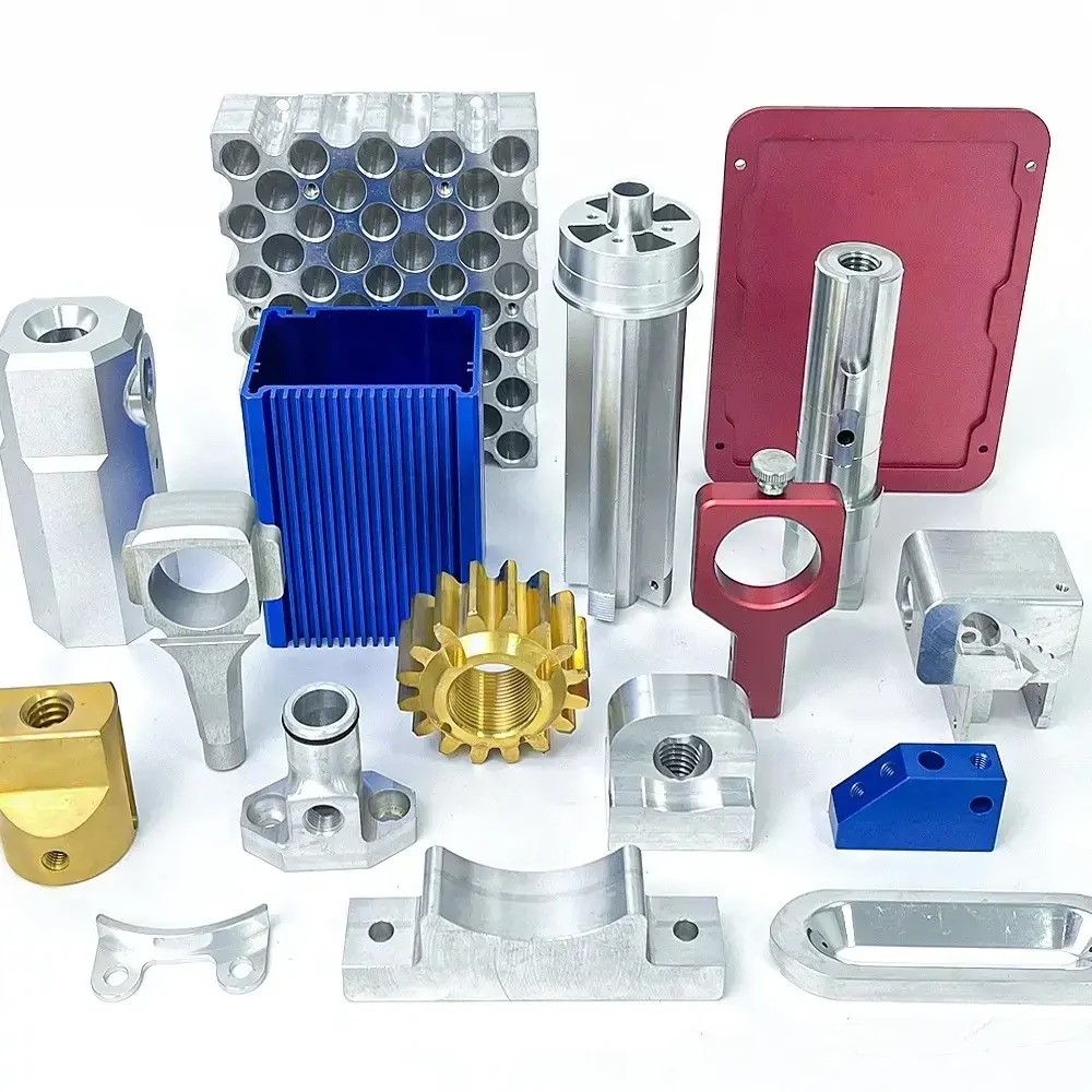
What this page covers
Machining paths, blade geometry limits, material and tolerance choices for aluminum impellers.
Why aluminum impeller processing CNC is usually a 5-axis job
An impeller is a set of curved blades around a hub. The blades lean, twist and taper, so a straight tool coming down the Z axis cannot reach the whole surface without hitting the blade next to it. That is the whole reason aluminum impeller processing CNC is normally quoted on 5-axis machines. Two rotary axes let the tool stay normal to a ruled or swept surface while it works between two adjacent blades.
At GreatLight we run 16 simultaneous 5-axis machining centers, plus 12 four-axis mills and 27 three-axis machines. That mix matters for costing. A simple open radial impeller with straight blades and no shroud can often be cut on a 4-axis mill with the table indexing between blades, especially when the back side is a simple turning profile. The tighter the blade twist, the more of the part has to be cut in simultaneous 5-axis motion.
Roughing and finishing are planned as two separate operations. Roughing removes the bulk of the material between blades with a large bull-nose or a high-feed cutter, leaving 0.3–0.8 mm of stock on the blade surfaces. Finishing then runs a ball-nose tool along the blade at small stepover. On aluminum this keeps the radial depth of cut low and the surface consistent, which matters later when the part is balanced.
- 1Open radial impellerStraight or lightly curved blades, no shroud ring. 4-axis with indexing is usually enough.
- 2Shrouded impellerClosed channel between hub and cover. Needs a 5-axis tool reach through the inlet or a split design.
- 3Splitter bladesShort blades between main blades. Tool access gets tight; check the gap in CAD first.
Blade wall thickness and channel width: the two numbers that decide feasibility
Most impeller problems are not about the machine. They are about two dimensions on the drawing: the blade wall thickness and the narrowest channel between two blades. A blade that is 1.5 mm thick at the tip and 3 mm at the root can be machined in aluminum with light finishing passes. A blade at 0.6 mm with a 90 mm unsupported span will deflect and chatter, and no toolpath trick fixes that.
The rule we use is simple. The channel must be wider than the tool shank plus clearance, not just the cutter diameter. A Ø6 mm ball-nose cutter with a Ø6 mm shank can enter a channel around 8 mm wide at the top, but the shank rubs as the tool leans over. If the channel narrows toward the hub, the deepest reachable point is set by the shank, not the tip.
Blade height also drives the tool length. A long tool with a small diameter bends under cutting load. On a 70 mm tall blade we prefer a tool with a 4:1 length-to-diameter ratio at most for finishing, and we accept a shallower depth of cut on the last passes instead of pushing a slender tool. That is slower, but the blade stays within tolerance.
- 1Thin blade tipBelow about 1 mm at the tip, expect to add support or accept a slower finishing pass.
- 2Narrow channelCompare channel width to shank diameter, not cutter diameter, before quoting.
- 3Long unsupported bladeOver 5:1 height-to-thickness usually needs a redesign or a different process.
Aluminum grades for impellers: where each one fits
Grades we machine regularly. Choice depends on speed, corrosion exposure and whether the part is welded or anodized.
| Grade | Typical use | Notes for machining |
|---|---|---|
| 6061 / 6061-T6 | General impellers, blowers, pumps | Easy to cut, welds well, anodizes evenly |
| 7075 | High-speed rotors, thin blades | Stronger, less corrosion resistant, harder to anodize |
| 2024 | Fatigue-loaded rotating parts | Good fatigue strength, lower corrosion resistance |
| 5052 / 5083 | Marine and wet environments | Best corrosion resistance, gummier chip |
| 6082 | Structural hubs and covers | Similar to 6061, slightly higher strength |
| ADC12 | Die-cast housings around impellers | Cast, not machined from bar |
Tolerances, surface finish and balance after machining
For most aluminum impellers, the critical features are the bore, the hub faces and the blade tip clearance. We hold ±0.005 mm (±0.0002 in) on the bore and hub datum when the drawing calls for it. Blade surfaces usually sit at ±0.05 mm because the aerodynamic profile tolerates more than the mounting features do. Tightening blade tolerance beyond that raises cost quickly and rarely helps the flow.
Surface finish on the blade path is typically Ra 0.8–1.6 μm off a ball-nose finishing pass. Where a smoother path is needed, we run a finer stepover and can reach Ra 0.2–0.8 μm. As-machined aluminum at Ra 1.6–3.2 μm is fine for non-critical air paths.
Balance is a separate operation, not a machining feature. After machining we check the part on a balancing stand and remove material from the hub where the drawing allows it. We do not claim a balance grade here because it depends on the rotor speed and the assembly it goes into. Tell us the final RPM and we will discuss what the drawing should specify.
- 1Bore and hubHold ±0.005 mm when the impeller is press-fit or keyed to a shaft.
- 2Blade profile±0.05 mm is a normal starting point for an aerodynamic surface.
- 3Blade finishRa 0.8–1.6 μm from a finishing pass; finer on request.
Fixturing, tool access and inspection
Impellers are awkward to hold. The hub is small and the blades are the part you must not crush. The usual setup is a soft jaw or a dedicated fixture that grips the hub from the inside or clamps the back face, with the blades hanging free. On a Ø400 mm rotary table we can swing larger impellers, but the fixture still has to clear the blades as the table rotates.
Tool access is checked in CAM before the job runs. We simulate the full 5-axis path, including the holder and the shank, and look for collisions between the tool body and the opposite blade. If a channel is unreachable, we tell you before cutting rather than after. Options are a redesign, a split impeller that is bolted or welded, or a different process such as casting or 3D printing for the prototype.
Inspection of a curved blade is done on the machine and at the bench. We check the bore and hub on a CMM, and we check blade profiles with a scanning routine or by sectioning a first article. Every part gets a raw material check, in-process monitoring and a final inspection before shipment, and reports are available on request. If a drawing has a true-position callout on the blade, say so early, because it changes the inspection plan.
- 1Grip the hubClamp on the bore or back face, never across the blade tips.
- 2Simulate the holderCollision checks must include the shank and holder, not only the cutter.
- 3Split when neededA bolted or welded two-piece impeller can open up closed channels.
Questions engineers ask before releasing an impeller drawing
Can a closed or shrouded impeller be machined in one piece?
Sometimes. The channel between hub and shroud has to be wide enough for the tool and its shank to reach through the inlet or an opening. On small shrouded impellers the channel is often too narrow, and the practical answer is a split design that is bolted or welded after machining.
Send the solid model and we will run an access check before quoting. That takes less time than discovering the problem after the first cut.
What is the thinnest aluminum blade you can hold tolerance on?
It depends on the unsupported length, not the thickness alone. A blade around 1.5 mm thick with a short span machines fine. As blades get closer to 1 mm at the tip and the span grows, deflection and chatter appear and we have to slow the finishing pass.
Below roughly 5:1 height-to-thickness we usually recommend a design change or a different process.
Do you machine the impeller from bar stock or from a casting?
Both. A prototype is normally cut from aluminum bar so the geometry can be proven before tooling exists. Higher volumes can start from a casting and then be finish-machined on the critical surfaces.
The choice affects lead time and cost, so tell us the expected quantity with the drawing.
How do you handle balancing?
Balancing is done after machining, with material removed from the hub where the drawing permits. The acceptable residual unbalance depends on rotor speed and the assembly, so we ask for the target RPM.
We do not publish a balance grade because it is a property of the finished rotor, not of the machining operation.
Which file formats and information do you need for a quote?
A STEP or IGES solid is best, plus a 2D drawing for tolerances, surface finish callouts and the datum scheme. Note the material grade, the quantity and any anodizing or coating requirement.
Quotation and free DFM analysis come back within 12 hours, and production can start within 24 hours after that.
Can you keep the impeller design confidential?
Yes. Uploads are secure and confidential, and we sign an NDA on request before files are shared.
We do not reuse customer geometry or publish part photos without written permission.
Send an impeller model and get a machining plan
Upload a STEP file with your tolerances and quantity. You get a quotation and a free DFM analysis within 12 hours, and every part is inspected before it ships.
12-hour quote and DFM±0.005 mm toleranceNo minimum order quantityNDA on request









