
Aluminum Alloy Parts Hand Plate Processing: From Sketch to Machined Part
A hand plate is the first physical part built from a drawing, before tooling exists. This page explains how this workflow actually runs on a CNC floor, which geometry suits it, and the point where the hand-built plate stops being the right choice.
In this article
- 1
- 2
- 3
- 4
- 5
- 6
- 7
What Aluminum Alloy Parts Hand Plate Processing Means
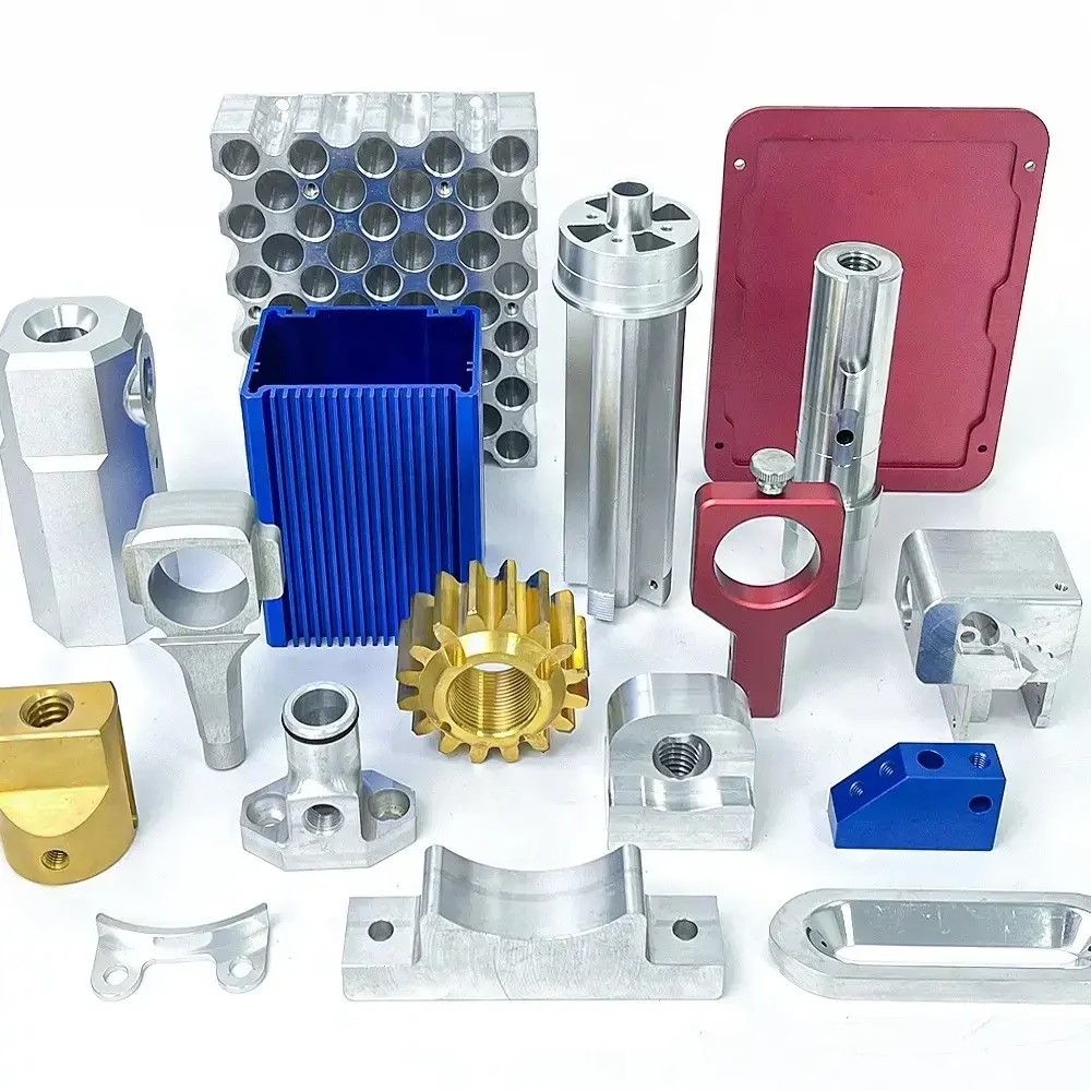
In job shops, a hand plate is the first machined sample of a part that will later be cast, forged, molded or stamped. The drawing arrives, no tooling exists yet, and you still need a real part in your hands to test fit, weight and function. The term covers both the workflow and the output.
The workflow starts from a 2D drawing, a 3D model or even a marked-up sketch. An engineer turns that into toolpaths, and a machinist cuts the geometry from billet. The output is a single aluminum piece that matches the intended production dimensions closely enough to assemble and measure.
Hand plates exist because tooling is expensive and slow. A die for a die-cast housing can take weeks and cost more than the first hundred machined parts combined. Cutting a plate first lets you catch a wrong boss height or a missed clearance before anyone commits to steel.
The name comes from an older practice. Patternmakers once shaped these first samples by hand, filing and fitting until the part worked. The intent has not changed. Only the tools have, and a CNC spindle now holds tolerances a file never could.
Which Part Features Suit Hand Plate Machining
Not every design is a good fit for this route. The method rewards parts that are small enough to hold on a vise or fixture and simple enough that most features can be reached from a few directions. If the part fits inside a 500 × 500 × 450 mm envelope, a 3-axis or 4-axis setup usually covers it.
Undercuts, deep internal channels and features on five faces push the job toward a 5-axis machine or multiple setups. Each extra setup adds a re-clamp, and each re-clamp adds stack-up error. A part with six critical faces is workable, but the cost and risk climb fast.
Wall thickness matters more than overall size. Thin aluminum walls deflect under cutting force. Below about 1 mm, chatter and spring-back start to show in the finish, and the part may need light finishing passes or a support fixture to hold shape.
Cosmetic surfaces are another boundary. A hand plate is machined, so it will show tool marks unless you specify bead blasting, brushing or anodizing. If the final product is a molded shell with a textured finish, the plate can only approximate that look.
How the Cutting Process Actually Removes Material
Aluminum cuts fast and generates heat quickly. A two-flute or three-flute carbide end mill at 8,000 to 12,000 rpm with a chipload of 0.05 to 0.15 mm per tooth clears material efficiently, but only if chip evacuation keeps up. Recutting a chip is the fastest way to break a tool and burnish the wall.
The alloy choice changes the cutting behavior. 6061-T6 machines cleanly and holds a good finish. 7075 is stronger but more abrasive and prone to chipping at the edges. 2024 tends to gum if the coolant is weak. Cast alloys such as ADC12 cut easily but may contain porosity that shows up after the final pass.
Heat is the real limit. Aluminum conducts heat away from the cut zone quickly, so the tool edge stays cooler than in steel, but the workpiece grows. On a long plate, thermal expansion of 0.02 mm across a 300 mm length is normal. Rough, cool, then finish, and measure at room temperature.
Clamping force is the quieter problem. Over-tightening a vise bows a thin plate upward in the middle. The cut looks fine on the machine and the part springs flat after unclamping, leaving a concave face. Support the underside and use light clamping pressure on anything under 6 mm thick.
How to Check a Hand Plate Before You Trust It
A hand plate is only useful if you know what it tells you and what it does not. Dimensional checks confirm the geometry. They say nothing about fatigue life, corrosion behavior or how the part performs once it is cast instead of machined.
Start with the interfaces. Measure the mating faces, hole positions and clearances first, because those decide whether the part assembles at all. Then check the critical tolerances from the drawing. Everything else can be verified with a caliper and a height gauge.
Record the measurement temperature. Aluminum expands by roughly 23 μm per meter per degree Celsius. A plate measured at 30 °C reads about 0.07 mm longer over 100 mm than the same plate at 20 °C. That is larger than many of the tolerances on the drawing.
Do not read the finish as a production spec. A machined face at Ra 0.8–1.6 μm is smooth, but a cast or molded surface will not look the same. Judge the plate on geometry and function, and treat surface appearance separately.
When Hand Plate Processing Is the Wrong Choice
The method loses its advantage once volume enters the picture. Machining a part from billet makes sense for one to a few hundred pieces. Past that, the per-part cycle time and material waste start to outweigh the tooling savings of a cast or molded route.
Very large parts also push the limits. Our largest travel reaches 4,000 × 400 × 150 mm, which covers long rails and panels. Beyond that envelope, the part must be split, welded or moved to a different process entirely.
Parts with internal cavities, thin shells or drafted walls designed for molding often cannot be machined as drawn. A mold needs draft angle and uniform wall; a machined plate needs tool access. Sometimes the drawing has to be adjusted before either route works.
Finally, material properties can differ. A machined 6061 plate is wrought and has directional grain. The same part cast in ADC12 is isotropic but more porous. If the plate is meant to predict cast behavior, the test measures the geometry, not the material.
Step by Step: Building an Aluminum Hand Plate
The sequence a shop follows from file to finished plate.
- 1Review the model and drawingCheck units, datums and tolerances. Flag any feature thinner than 1 mm, any tolerance tighter than ±0.005 mm, and any callout that cannot be measured with standard gauges.
- 2Fix the setup planDecide how many setups the part needs. Aim for one op-1 face that carries the primary datum, so later features reference a surface already cut on the machine.
- 3Choose the alloy and stock6061-T6 for general work, 7075 for loaded brackets, 2024 where fatigue matters. Order stock with 1–2 mm of allowance on each face for cleanup.
- 4Rough and stress-relieveLeave 0.3–0.5 mm on critical faces. For thin or long plates, let the part rest or run a light stress-relief pass before finishing.
- 5Finish cut and control heatUse higher spindle speed, moderate feed and flood coolant. Take light finishing passes at 0.1–0.2 mm radial depth to hold the wall straight.
- 6Deburr and inspectBreak edges, measure at 20 °C, and record the readings. Compare against the drawing before the plate goes to assembly.
- 7Apply finish if neededAnodizing, bead blasting or laser marking. Marking needs at least 1.5 mm character height to stay legible after anodizing.
Hand Plate Machining vs Production Tooling Routes
Use this to pick a route before committing budget.
| Route | Typical lead time | Best for | Main limit |
|---|---|---|---|
| CNC hand plate | Days | Fit checks, functional tests, small runs | Unit cost stays high |
| Die casting | Weeks plus tooling | High-volume housings, complex ribs | Tooling cost, no early samples |
| Sheet metal | Days | Flat brackets, enclosures, panels | Limited 3D geometry |
| Vacuum casting | Days | Urethane copies of a master pattern | Not a metal part |
| Injection molding | Weeks plus tooling | Plastic parts at volume | Wrong material for metal duty |
| 3D printing | Hours to days | Form and fit only, no load | Weak layer direction, poor tolerance |
The Short Version
If you need one to a few hundred aluminum parts to prove fit and function before tooling, machine the hand plate. If the part is already at volume, or its walls and draft exist only for molding, skip the plate and go straight to the production process.
Hand Plate Questions Engineers Ask
Can you machine a hand plate directly from a hand drawing?
Yes, if the drawing carries enough information. We need dimensions, tolerances, datum callouts and material. A sketch with a few overall sizes and no tolerance scheme will need clarification first.
We return a DFM note within 12 hours listing the missing values and any feature that cannot be cut as drawn.
What tolerance can a machined aluminum hand plate hold?
Down to ±0.005 mm on critical features under good conditions. That is not automatic on every dimension. Thin walls, long spans and deep pockets open up the tolerance band.
Tell us which dimensions matter and we will focus the setup and inspection on those.
How many setups does a typical hand plate need?
Most 3D parts need two or three: a primary face, a secondary face, and one for side holes or slots. A 5-axis machine can collapse several of these into one setup.
Fewer setups mean less stack-up error. If a feature is critical, we try to cut it in the same setup as its datum.
Which aluminum alloy should the hand plate use?
6061-T6 for general parts, 7075 for high-load brackets, 2024 where fatigue resistance matters, 5083 or 5052 for weldments. We stock all of these.
If the production part will be a different alloy, test the hand plate for geometry and fit, then confirm the material change separately.
Can the hand plate be anodized or marked?
Yes. Clear, color and hardcoat anodizing are available, along with bead blasting, brushing and laser marking.
Laser marking needs a minimum character height of 1.5 mm, and anodizing adds a thin oxide layer that shifts tight tolerances slightly. Plan for that in the drawing.
What is the smallest quantity you will run?
One piece. There is no minimum order quantity, and the same setup supports runs up to 10,000 parts and beyond.
For a single plate we still inspect 100% before shipment and can supply measurement reports on request.
Send the Drawing, Get a Machined Plate
Upload your file and we return a quotation with free DFM analysis within 12 hours. Prototypes can start production within 24 hours.
12-hour quote100% inspectionNo minimum order
Follow GreatLight
We publish setup notes, tooling trials and inspection data from the factory floor.











