selective laser sintering (SLS) 3DPrintTechnology enables superior quality and productivity, while opening up a wide range of high-performance designs not possible with injection molding. Door.SLS Additive manufacturing also eliminates long lead times and the initial investment in injection molding molds. If finished parts are measured in three dimensions: quality, time to market and cost per cubic inch, in many cases the industrial results SLS All offer a better total value proposition.
This guide is included in Designed to be used SLS Specific details on how to ensure success in building better parts when building technologies, such as shafts, frames, complex pipelines, movable hinges, clamps, and other components.
A,axis
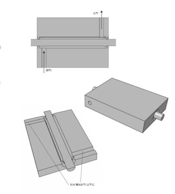
Rubbing, adjusting and depowdering areSLSThree factors in manufacturing shaft design. on the static side(The “unconstrained” side of the component)application1has2mmguide rails to control friction. The space between the guide rail and the shaft tube is kept at0.3mm. If you leave an area far from the guide rail2mmFor the above spaces, powder can be easily and completely removed by blowing compressed air through the powder removal inlet on the static side.
When removing the powder, compressed air is blown while rotating the shaft to blow the powder out of the shaft cavity. As a natural bearing material, nylon provides a smooth, low-friction mechanism for low-load, low-speed applications. In more demanding applications where friction can generate heat and cause wear, insert bearings may be considered.

two,Baffle – air flow management
If the mounting point passes through the baffle, lengthening the baffle and creating an aerodynamic teardrop shape reduces where turbulence can form. This improves airflow efficiency and reduces noise.
Always design baffles with slightly rounded corners to prevent cracking of the pipe sidewalls, particularly if the assembly is used in a pressurized environment and/or temperature cycle environment.

three,Integrated bearing
In this example we cover the installation of ceramic ball bearings in grooves(CAD Modeled as A、B an annular cavity between the faces) Inside. Think of it as a built-in hybrid hinge mechanism.
Nylon is a naturally supportive, low friction material. However, if you hope to be able to re- For multi-cycle charging applications it will be used GUJAT The modeled ball bearings already in place are replaced by ceramic ball bearings(Installation via manhole)you can get a very durable and smooth mechanism.
Once all the bearings are in the groove, a pin can be attached to seal the groove.

Four,barcode
Aztec barcode can be usedSLSfor manufacturing. Cell size may be less than1cubic millimeters. Please note that contrasting ink must be used on the raised side of the barcode to allow or facilitate capture of the image when the scanner scans it.

five,bellows
Use when the application’s assembly or assembly operations require a certain degree of flexibilitySLStechnology to create functional “bellows”. Note, however, that nylon does not perform well in applications that require repeated cycling, such as protecting wires and pipes in institutions. Therefore, nylon should only be considered for bellows in applications where the cyclic bending frequency is extremely low.
Circular bellows work best when the tensile stress points are evenly distributed along the cross section. When transitioning from a round bellows to a square bellows, any downward movement from the round will accumulate stress. In this case, you may need to take a different approach:“Deardorff“Bellows” uses a similar structure, which is essentially a series of alternating interconnected rectangles. Note that this geometry is more sensitive to stress concentrations due to the smaller corner radii and is therefore subject to easy cyclic failure under stress.

six,Blind boss
Blind holes present a challenge for efficient powder removal. The solution presented here is to make these blind holes less difficult to manage. Simply drill a hole in the base of the boss with a diameter greater than2mmholes to allow the sandblasting material to flow.
No undercut is required, but in the case of plastic self-tapping screws it is best to follow normal design principles when designing the surfaces that will engage the teeth.

Seven,button
There are many different ways to design built-in buttons. Let at least0.3mmspaces to prevent them from melting together. Since nylon “spring sheets” tend to deform in a slightly depressed position, they should also be usedGUJATModel the button to be higher than the desired final position. For example, if you want a button to be flush with a surface and you model it that way, you will find that after several repeated presses the button will stay below the surface.

As for the leaf spring, its degree of deformation depends on the density of the spring as well as its length and thickness. The top and bottom button as shown below is calledA form of leaf spring for a “bistable” switch. In such cases, the button resists and then slowly moves to a distorted position, sometimes with a click.
8. Structure
SLSThe manufacturing technology is ideal for making many small, complex plastic parts, such as electrical connectors and clips. Can take the exam
considerGUJATWhen designing, use boxes to surround these small parts to prevent them from being lost during failure and post-processing.
lose.1.0mmsquare strips5mmThe openings above allow sandblasting agents to group clean parts inside the frame.
In applications requiring additional post-processing, such as sterilization for surgical applications, parts from the batch can be processed within the framework.
Transition to different processes. To delete parts, consider usingGUJATModel the design of multiple hinges applied to the demolding area
Chain gate, or as in this example, connect the cover to four corner bars which can be cut with wire cutters.
Another option is to use connecting rods, which can also achieve the same effect as using injection molded sprues on some toy sets.
A similar batch grouping effect is achieved.

9. Chain
Like chainmail, the design usesSLSChannels made with technology would be very interesting. It is also a very old geometric shape that offers many possibilities for creating new and interesting shapes.
The first chains were hammered iron bars/Cast in such a way that it bends to form interconnected rings. to useSLStechnology to make chains, the only limit to designing chains is your imagination. You can even make a bicycle chain: just leave a0.3mmgap.

10. Basic Chain Armor
For basic chain mail, the thickness of the retaining ring is greater than0.75mmthe gap between the rings is greater than0.5mm. For larger base chain mail, consider designing the ring with a polygonal section in both axes. This reduces file size and speeds up the design process.
Before replicating the chain on a large scale, take the time to optimize each link in the chain. You might consider using polygons instead of circles to speed up ring duplication and replication.GUJATfunction.
You can fold your design like fabric to reduce the bulk of your design components. Special precautions must be taken to avoid overlapping rings.
Regarding the effectiveness of the bounding box, you may want to consider folding and/Or telescope large arrays of rings to reduce the space the design takes up.

11. Intricate chain armor–Mobius Elastomer
When it comes to designing complex technical fabrics or chain mail, your creativity is the only limit. In this example, a three-sided Möbius strip not only forms an interesting structure, but also forms an array of elastic rings where each ring can be stretched in all directions.
Consider chain mail made into plates or chain mail, where the rings become progressively thicker in controlled areas that allow opacity and flexibility.
The inclusion of long spikes in each loop, combined with hooks for quick release and attachment, gives rise to the use of some interesting fabrics in new applications within the fashion industry.

12. Helical spring
One of the most important features to consider when dealing with coil springs is the use of large fillets where the spring connects to other objects. Particular attention should be paid to sharp tips.
As with all materials, cracks can quickly appear when cyclic loads are applied. As with leaf springs, the final stable position of a coil spring becomes apparent after several cycles of compression and extension.

13. Complex pipelines – Ribbon
Using SLS technology to manufacture low-volume, non-structural pipes such as those used in aerospace and performance racing ECS Pipelines enable the design of very complex and highly optimized monolithic structures. Not only can you design different wall thicknesses, but you can also increase the strength-to-weight ratio by applying structurally optimized surface webbing. If this detail is applied based on traditional manufacturing technology, the cost will be relatively high. And use SLS There are no additional costs due to complexity.
May be considered for use GUJAT Model a chain passing through a pipe. When finished, a quick pull of this chain through the pipe opens a smooth path for the blasting agents to have good cleaning speed through the pipe.

14. Grooved seal ring
manufacturingThe “negative pull” function is an interesting way to secure soft elastic products.(like a rubber seal)method. you can
Some experimentation will be necessary depending on the specific hardness of the joint. Generally, the minimum width is less than that of the joint in the uncompressed state.
Bottom diameter10%The sealing groove can accommodate and retain the gasket.
Note that this principle also applies to the attachment of other elastic components, such as joints and rows of buttons.

15. Viscose line
To achieve a tight, gap-free connection, connect the intersection points of GUJAT Modeling input/Outlet Port, Two-Piece Vacuum Thermosetting Epoxy(rather than pushing) in the radial canal. This is a good method for complex connection situations where tightness must be ensured.
Once attached, it cannot be removed without damaging the physical parts. Separate them below. Always suck the glue out of the canal. Don’t bet injected with epoxy as it will likely flow in the path of least resistance and Paths around connected areas may not be completely filled. The cross section on the right shows the glue(black) is drawn into the radial cavity through the manhole.

16. Grid
Hexagons are particularly targeted SLS technology, not only because they fundamentally manage the stress and efficiency of the hive, but also because they require very few triangles(12 individual) That is, the hexagon can be expressed precisely.
If you use circles to form the grid holes, expect the file size to increase significantly.
Although the weight of the final part may be reduced compared to a solid section without mesh, this increases the cleanup time and drawing time of the system since the laser now traces the contour and fills many cross-sectional features.
As with hollow parts, the amount of unused powder does not have a very big influence on the additional material used for recycling. This is due to the proximity of thermal exposure to the components. In fact, the cost of manufacturing mesh parts is higher than the cost of manufacturing solid parts due to the additional drawing time required.

17. Integrated hinge
The sphere in the rotating trapezoidal cone greatly contributes to the integrated hinge, which has good stability, precision, low friction and high yield strength. Leave a minimum space between the insert ball and the hinge sleeve0.2mm gap.
stay somewhere else 0.3mm above the gap. You will also want to continue drilling the hinge sleeve on the side. This has no effect on the hinge, but allows for faster and more complete powder removal.

18. Mother-child hinge
The balance between functionality and quality of this machine comes into play when it comes to the effects of tolerances. If the gap is too small, the hinge mechanism will be welded together, and if the gap is too large, the hinge mechanism will be loose and unreliable.
One way to solve this problem is to use some form of rotating the hinge into a flush position. During the construction process, when the hinge is disengaged, the tolerance may be greater than1mmlarge tolerances, when the tolerance is approx.0.05mmthe hinges produce a flush, tight and stable interaction within the operating range of the rotating joint.

19. Movable hinge
living hinge forSLSis newer and generally not the ideal solution when it comes to articulation. The question to ask here is: why build a living hinge when you can design and build an integrated hinge?
Conventional living hinges are designed and optimized for thermoplastic injection molding materials and processes.
ForSLSplease try to avoid moving hinges asSLSNylon does not have the flex characteristics of injection molded thermoplastics. This is due to the resolution of the process…3DPrinted hinges need to be thicker than hinges designed to be cast and nylon tends to perform better when exposed to cyclic deformation conditions. Living hinges are useful in applications with disposable foldable use cases and the ability to connect components together.
As for the direction of construction, try to avoid stepped steps that will coincide with the stretched surface of the hinge. Also remember to immerse the nylon in boiling water before folding it.10minutes to harden(annealed)。

20. Design for installation
An extended joint mounting point allows you to see the thermoplastic changes on the longest section you see. Each 100mm with the lowest 5mm The elongation rate lengthens the mounting hole.

21. Lattice structure
Lattice structures and other materials designed to be porous allow designers to place materials only where they are needed for a specific application. From a mechanical engineering perspective, one of the main advantages of porous materials is their high strength but relatively low mass.
These materials have good energy absorption properties as well as good thermal and sound insulation properties. Porous materials include foams, honeycombs, mesh and similar structures.
The process of manually building a truss structure can be tedious, so a designer may want to create a macro or program to automate certain steps, or use a specialized software package that automates the construction process.
SLSThe machine is capable of manufacturing diameters as small as almost0.5mmlattice pillars.

Twenty-two, clip buckle
There is a lot to do SLS Built with a successful plastic clip buckle design. Compared to injection molding,SLS The construction method reduces constraints on design complexity, allowing for much more complex clamping, ratcheting, securing and releasing systems.
In this example,The “press-release” button mechanism rotates both grip arms around a pivot point on the torsion beam. Note the extensive use of rounded corners to prevent breakage, as well as the distorted closed position of the clamping teeth to counteract the effects of initial cyclic creep.
As with all beams that undergo cyclic deformation, you must account for the initial creep that the plastic will experience before reaching its final stable position.SLS The design of how it is constructed is crucial.
As with live hinges and leaf springs, consider submerging them in boiling water 10 minutes to improve the toughness and memory of plastic.

23. Label
Tags attached by chains or sacrificial rods are markersSLSCommon methods for widgets.Sprint 3D®The software can performSTLFile names automatically label parts. This approach is particularly useful in custom mass manufacturing applications. Try to keep all layers at1mmThat’s all.
Note that in the illustration, for connections to“Hang tag” connector, the connection between the rod and the component is located in a recessed threaded groove. This reduces the impact on the mechanical integrity of the component. Also note the snap points in this use case, the connecting rod is cast with aVshaped space. If you want to easily control tag removal and use a chain connection, you can also use the same method.
WillVThe profiled notch is placed in the recessed groove, which will not leave any traces that affect the assembly after disassembly of the hang tag.

Twenty-four, boxes and jars
to useSLSProperly sintered nylon material.(density greater than0.98 g/ccthe wall thickness is greater than1mm)Capable of storing liquids and gases under pressure. For corrosive solvents and fuels, consider usingImprexPerform penetration. Typically, the component cake inside the tank, which is bounded by geometry and exposed to additional heat, can become very dense and require additional labor to completely disassemble.
For air ducts, consider using nesting tools and providing powder removal aids. In this case, a combination of rods and chains are used simultaneously to cut the cake of material and remove it from the inside corners.
Generally, the chain/The diameter of the connecting rod is greater than2mmThat’s enough. You can also mold a rod inside a hollow cone that connects to the air line. Once this connection is removed, you will be able to blow compressed air from below.

25. Design tear openings
Controlled tearing or failure can be achieved using the traditional approach of physically designing a notch into the geometry.
However, usingSLSManufacturing Methods, you can also selectively control the density of specific areas of your product.
Areas where you want them to be low density can be usedGUJATmodeled as separateSTLshell files to achieve this goal. When parts are placed on the machine as assemblies, be careful not to snap the housings apart.
On the machine, reduce the amount of laser exposure to the hull whose density you want to reduce. This allows the selective creation of regions of low density and therefore greater susceptibility to fracture.
Note that materials that receive less densification shrink less. Areas of lower density will be more sensitive and opaque than surrounding areas of higher density.

Twenty-six, wire
because SLS The surface treatment is relatively rough and friction can sometimes interfere with the threaded mechanism.
In this example, the external thread is replaced by“Hemispherical”, aligned with the groove on the back of the component.
By taking this approach, friction is significantly reduced while increasing“Cooperate and surrender.”
Plasticization occurs when both parts are subjected to the same process changes.SLS Very sensitive to process changes.
For example, when the laser beam is poorly offset, the front side will be larger and the back side will be smaller, resulting in increased interference.
This example is a great example of how threads are unbound by traditional design methods and are inspired by the desired functional goals of the mechanism.

Daguang focuses on providing solutions such as precision CNC machining services (3-axis, 4-axis, 5-axis machining), CNC milling, 3D printing and rapid prototyping services.