This information is based on the FANUC system tour and I hope it will be useful to gold enthusiasts in their work and studies.
1. G00 rapid positioning command
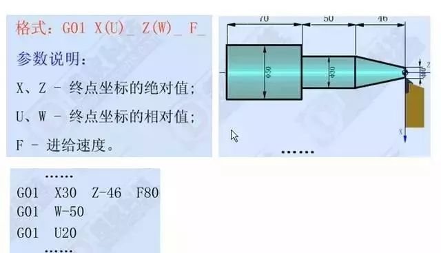
2. Linear interpolation command G01
3. G02 clockwise arc interpolation command
4. Counterclockwise arc interpolation command G03
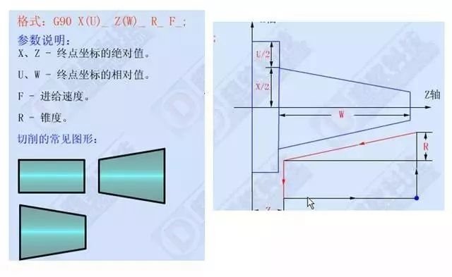
5. G90 outer circle and inner circle turning cycle control
6. Outer circle rough turning cycle control G71
O0001;
G98;
M03 S500 T0101;
G00 X82 Z3;
G71 U1.5 R0.5;
G71 P1 Q2 U0.5 W0.1 F120;
N1G00X0 ;
G01 Z0 F80 S1000;
X20;
X24 Z-2;
Z-20;
X30;
X32 W-1;
Z-40;
X42;
X48;
W-11;
G02 X58 Z-55 R5;
G01 X72;
X76 W-2;
N2X82;
G70 P1 Q2;
G00 X100 Z100;
M05;
M30;
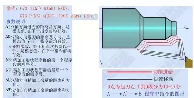
7. Closed cutting cycle control G73
O0001;
G98;
M03 S500 T0101;
G00 X48 Z3;
G73U5R5;
G73 P1 Q2 U0.5 W0 F150;
N1 G00 X44 Z1;
G01 Z-15 F100 S1000;
G03 X34 Z-35 R45;
G01 W-5;
X44 W-1;
N2X46;
G70 P1 Q2;
G00 X100 Z100;
M05;
M30;
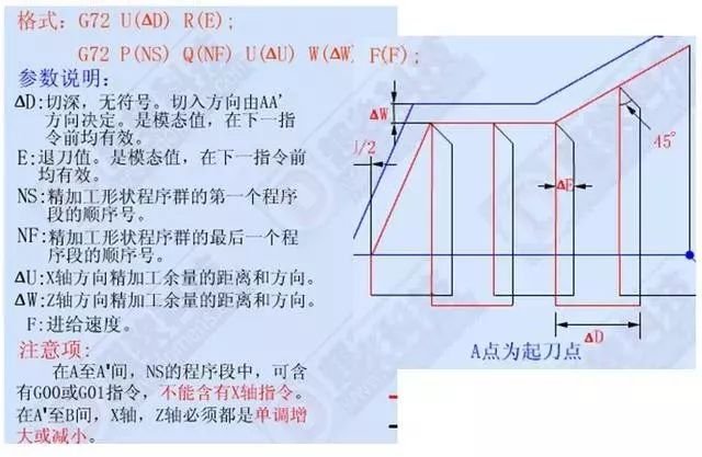
8. G72 end face roughing turning cycle control
G00 X52 Z2;
G72 W1 R0.3;
G72 P1 Q2 U0.05 W0.3 F100;
N1 G00 Z-12;
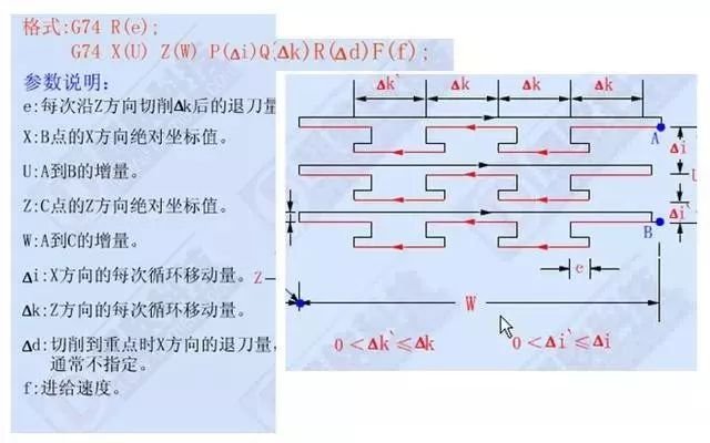
9. G74 end face deep hole machining cycle control
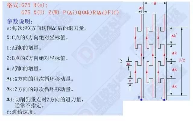
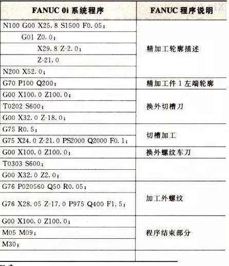
10. Outer circle and inner circle grooving cycle control G75
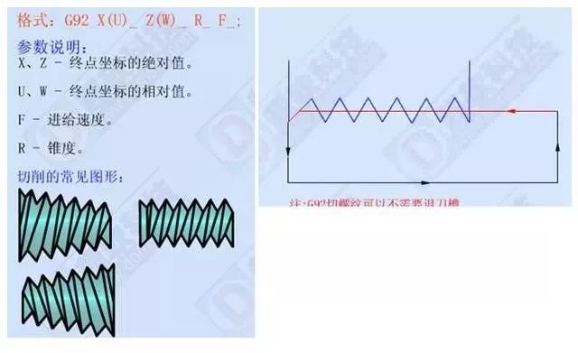
11. Threading cycle control G92
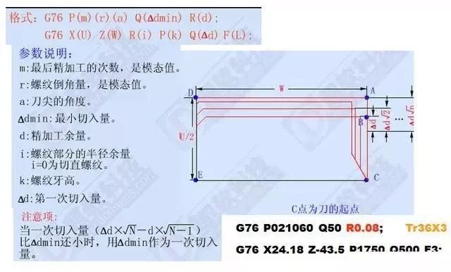
12. G76 compound thread cutting cycle control
Related knowledge points:
3) Determining the position of the cutting edge of the arc turning tool
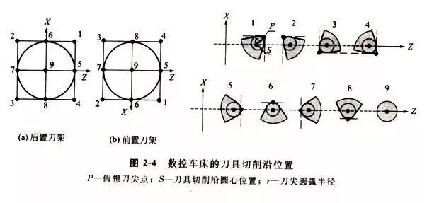
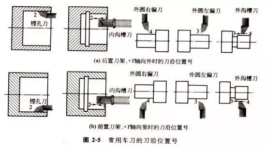
When a CNC lathe uses tool tip arc compensation for processing, if the shape of the tool tip is different from the tool position during cutting (i.e. i.e. the position of the tool cutting edge), then the amount of compensation and the direction of the tool compensation will also be different. According to the different tool tip shapes and tool tip positions, there are 9 types of tool tip positions for CNC turning tools, as shown in the figure. The cutting edge position numbers of commonly used turning tools are shown below.
4) Precautions for tool nose arc radius compensation
① The tool radius compensation mode set and cancel blocks are only valid in G00 or G0l motion control mode.
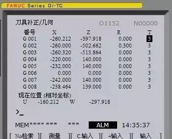
② G41/G42 has no parameters, and its compensation number (representing the tool nose radius compensation value corresponding to the tool used) is specified by the T command. The tool nose radius compensation number The arc of the tool nose corresponds to the tool offset compensation number.
③ Use tangential cutting method or normal cutting method to set or cancel knife compensation.
④ In order to prevent the tool from cutting too much during the setting and cancellation of the tool radius compensation, when setting and canceling the compensation, the starting position and the position end of the program segment must be on the same side as the compensation direction.
⑤ In tool compensation mode, it is generally not allowed to have more than two consecutive no-move instructions in the compensation plane, otherwise the tool will also cause dangerous actions such as overcutting. Compensation plan still instructions generally refer to: blocks with only G, M, S, F, T instructions (such as G90, M05) and program pause blocks (G04 X10.0).
Daguang focuses on providing solutions such as precision CNC machining services (3-axis, 4-axis, 5-axis machining), CNC milling, 3D printing and rapid prototyping services.

