
What Software Is Used to Control the CNC Machine?
Four software layers sit between a CAD model and a finished metal part: CAD, CAM, the NC kernel inside the machine, and shop-floor tools for probing and inspection. This page explains what each layer does, where it stops being accurate, and how to tell which one is causing a problem on your part.
In this article
- 1
- 2
- 3
- 4
- 5
The NC Kernel: What Software Is Used to Control the CNC Machine in Real Time
When people ask what software is used to control the cnc machine, they usually mean the NC kernel. This is the real-time program running on the machine control unit. It reads G-code blocks, interpolates the axis motion, closes the position loop on the servo drives, switches the spindle speed, and fires the tool changer. It is not a design tool. It does not know what the part is.
A G-code line like G01 X50.0 Y20.0 F800 tells the kernel to move two axes at a feed of 800 mm/min along a straight line. The kernel turns that into a stream of position commands, thousands per second, and blends them so the machine does not stop at every block boundary. Look-ahead buffering is what allows a 5-axis tool path with 20,000 short segments to run smoothly instead of jerking.
Three control families cover most of the machines we run. Fanuc is the default on mills and lathes, with a large installed base and predictable behavior. Siemens 840D is common where high-speed contouring and 5-axis kinematic transforms matter. Heidenhain is strong on mold work because its conversational layer and fast block processing suit long finishing passes. The kernel is chosen when the machine is bought. You rarely change it later.
The kernel sets a hard ceiling on accuracy. If the servo loop and encoder resolution cannot resolve 1 μm, no CAM setting will produce a ±0.005 mm feature. This is why we match machine and control to the feature tolerance before quoting, not after the first article fails.
CAM Software: Turning a Model into Machine-Readable Code
CAM software is the translation layer. It imports a 3D model, lets a programmer define stock, fixtures and tool assemblies, then calculates tool paths and posts them into G-code for a specific machine and control. Everything the kernel executes was decided here: stepover, stepdown, feed, speed, lead-in, lead-out, entry style.
The choice of CAM package follows part geometry, not brand preference. Mastercam and NX handle complex 5-axis surfacing and blade-type geometry well, with mature collision checking against holder and fixture. Fusion 360 is a reasonable fit for simpler 3-axis and 4-axis work and for design iteration early in a project. Powermill-type packages target deep cavity finishing where constant tool engagement matters.
Post-processor quality decides whether the code runs the first time. A generic post may output valid G-code that still crashes, because it ignores the machine's rotary pivot distance, tilt limits, or spindle orientation. We verify posts against each machine's kinematic model before a new part family is released to the floor.
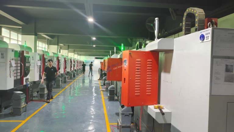
For simultaneous 5-axis work on our 16 machining centers, CAM also has to manage the rotary table and tool axis vector. A poorly chosen tool axis creates chatter at the tool tip even when the path looks clean in simulation. Simulation catches collisions. It does not catch poor cutting dynamics.
CAD Software: Setting the Geometry the Machine Will Chase
CAD defines the nominal shape. Every tolerance, datum and surface the shop works to comes from this file. In practice the file format matters as much as the modeling tool, because translation errors silently shift geometry. STEP AP242 carries PMI tolerance data. Native formats carry construction history, which helps when we need to adjust a feature for manufacturability.
Most engineering teams send SolidWorks, Creo, NX, Inventor or STEP files. We work from whatever is native to the customer and keep a translated STEP copy for the shop floor. When a model is only available as an STL mesh, the surfaces are faceted and the CAM system has to fit curves to triangles, which adds uncertainty to tight tolerances.
Modeling intent has a direct cost effect. A fillet modeled as a sharp corner forces the CAM programmer to add a radius manually, and the tool must reach it. A small internal radius that no standard end mill can enter will drive the part to EDM or to a smaller tool with a longer cycle time. Design for machining starts in CAD, well before a quote.
At GreatLight we run a free DFM analysis on every uploaded model, usually within 12 hours. The review flags thin walls, deep pockets, unreachable features and tolerance stacks that the process cannot hold, so the CAD file gets fixed before chips are cut.
Shop-Floor Software: Probing, Verification and Data
A fourth layer rarely appears in software lists but decides whether parts ship. Probe routines in the control measure the workpiece after clamping, find the actual stock position, and update work offsets. On a casting with ±0.5 mm stock variation, this step is what keeps the first cut safe and the wall thickness on nominal.
Inspection software closes the loop. CMM programs compare measured points to the CAD nominal, and the deviation report tells us whether the machine drifted, the tool wore, or the fixture moved. We inspect 100% of parts before shipment, with raw material checks, in-process monitoring and a final inspection, and reports are available on request.
Tool management and scheduling tools sit alongside. They track tool life by cutting time, warn before a finishing tool dulls, and sequence jobs across 127 machines. These are not glamorous, but a worn 6 mm end mill will destroy a Ra 0.8–1.6 μm finish far faster than any programming error.
The layers only work when they agree. A CAM file built on the wrong stock model, a probe routine measuring against the wrong datum, or a post that outputs the wrong rotary sign all produce the same symptom: a part that is dimensionally consistent but wrong.
What Each Software Layer Decides and Where It Fails
Use this table to route a problem to the right layer before changing settings.
| Layer | Owns | Typical failure |
|---|---|---|
| CAD | Nominal geometry, datums, tolerances | Sharp internal corners, unreachable pockets |
| CAM | Tool paths, feeds, speeds, G-code | Wrong tool axis, missed collision, bad post |
| NC kernel | Motion, servo loop, tool change | Resolution limit, look-ahead starvation |
| Probing / CMM | Work offsets, measured deviation | Wrong datum, uncalibrated probe stylus |
| Tool management | Tool life, offsets, job sequencing | Dull finishing tool, wrong length offset |
Where to Look First
If the part is dimensionally wrong but repeatable, fix CAD or CAM. If it is dimensionally inconsistent, look at the NC kernel, probing and tool life. Change one layer at a time and re-measure.
Common Questions
Can a machine run parts without CAM software?
Yes, for simple work. Conversational programming at the control, or manual G-code written by hand, is common for one-off fixtures, simple turned parts and repair work.
The limit is geometry complexity. As soon as the part needs 3D surfacing, multiple setups or simultaneous 5-axis motion, hand-written code becomes slower and riskier than a CAM path.
Does the CAM brand affect the price of my part?
Not directly. The price follows cycle time, setup count, tooling and inspection effort.
It affects price indirectly through path efficiency. A well-tuned path with constant tool engagement can cut finishing time noticeably compared with a naive raster path on the same geometry.
Can you work from a STEP file only?
Yes. STEP is our most common input format and it is enough to quote and machine most parts.
If the part has tight tolerance stacks or freeform surfaces, a native file or a drawing with datums and tolerances removes ambiguity and shortens the DFM review.
How do you handle a machine with an older control?
Older controls still machine good parts. The constraints are memory size, block processing speed and sometimes a smaller look-ahead buffer.
We adjust by shortening programs, splitting operations across setups and reducing the number of tiny segments in finishing paths. On tight-tolerance features we may move the job to a newer machine.
Is post-processor testing really necessary for every machine?
For new part families on a machine we have not run before, yes. Rotary pivot distance, tilt limits and spindle orientation are machine-specific values that a generic post gets wrong.
Once a post is verified against the machine kinematic model, it is reused. We keep a verified post per machine and control combination.
What tolerance can the software chain hold in production?
Our standard machining tolerance is ±0.005 mm (±0.0002 in), with surface finish from Ra 0.2–0.8 μm on fine work to Ra 1.6–3.2 μm as-machined.
Holding that in production depends on the whole chain: model accuracy, post correctness, machine condition, probing and tool life. Software alone does not hold a tolerance.
Send Us Your Model and Drawing
Upload a STEP or native CAD file and we return a quotation with a free DFM analysis, usually within 12 hours. Production can start within 24 hours, and there is no minimum order quantity, from one prototype to 10,000+ part runs.
12-hour quote100% inspectionNDA on request
More from GreatLight
We publish setup notes, tooling trials and inspection data from the factory floor.











