
What Is Mean by CNC Machine?
What is mean by cnc machine comes down to one idea: a computer reads a program and drives the cutting tool along a defined path. This page explains the mechanism, the machine types, the tolerances you can hold, and when CNC is not the right process for a part.
In this article
- 1
- 2
- 3
- 4
- 5
- 6
What Is Mean by CNC Machine in Plain Engineering Terms
CNC stands for computer numerical control. The machine does not cut from a drawing. It cuts from a list of coordinates that a controller turns into motor commands. Every straight line, arc, and drilled hole is a block of code with a position, a feed rate, and a spindle speed.
That is the whole idea behind what is mean by cnc machine. A human decides the geometry and the cutting strategy. The controller repeats the motion thousands of times with the same result. Manual machining depends on an operator turning handwheels and watching a dial. CNC machining depends on the program and the setup being correct before the first chip is cut.
The practical consequence is repeatability. Part one and part five hundred come off the machine within the same tolerance band, because the tool follows the same path at the same feed. A skilled operator still matters. They choose the tool, set the work offset, and listen for chatter. The difference is that their skill goes into the setup, not into every single cut.
- 1ProgramG-code and M-code define position, feed, spindle speed, and tool changes.
- 2ControllerReads the program and sends pulses to servo motors on each axis.
- 3Servo and ball screwConverts motor rotation into linear movement with low backlash.
- 4FeedbackEncoders or glass scales report actual position back to the controller.
The Control Loop That Turns Code Into a Cut
A CNC machine is a closed-loop positioning system. The controller compares the commanded position with the position reported by the encoder. If the axis lags, the controller increases motor current until the error closes. This happens many times per second, on every axis, for the whole cycle.
The mechanical chain matters as much as the electronics. A servo motor turns a ball screw, the ball screw moves a linear guide, and the guide carries the table or the spindle. Preloaded ball nuts and linear guide blocks keep backlash small, which is why a well-maintained machine can hold ±0.005 mm on a feature while a worn machine cannot.
Thermal growth is the quiet variable. A spindle running at 12,000 rpm warms up and grows in Z by a few micrometres. On tight work we let the machine warm up and, where the geometry allows, take a roughing pass, measure, then take the finishing pass with a fresh offset. That is a process decision, not a machine specification.
- 1RoughingRemoves most of the stock, leaves 0.3–0.5 mm for finishing.
- 2Semi-finishingBrings the wall close to nominal, controls stock variation.
- 3FinishingLight radial engagement, higher spindle speed, better Ra.
Machine Types and What Each One Is Good At
A 3-axis mill moves in X, Y, and Z only. The tool always approaches from one direction. That is enough for brackets, plates, housings, and most flat work. It is the cheapest way to remove metal, and on simple geometry it is also the fastest.
A 4-axis mill adds one rotary axis, usually A or B. The part turns while the tool cuts, so features on four sides can be reached in one setup. This removes the re-fixturing error that creeps in when you flip a part by hand. Gears, valve bodies, and long shafts with cross features are typical work.
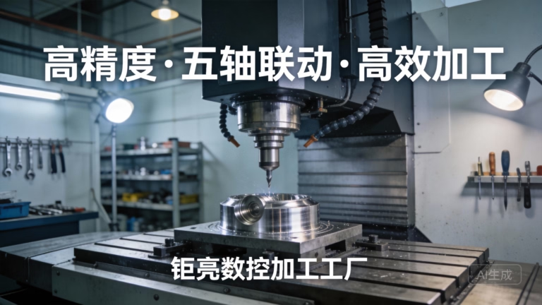
A 5-axis machine adds a second rotary axis, so the tool can tilt relative to the part. Two things become possible. You can reach undercuts and deep pockets that a straight tool cannot enter. And you can keep the tool axis normal to a curved surface, which lets a ball nose cutter use its tip instead of its flank. That second benefit is why impellers and medical implants are cut on 5-axis centers.
Turning is a different motion. On a lathe the part rotates and a single-point tool feeds along X and Z. Swiss-type lathes add a sliding guide bushing, so the tool always cuts close to the support. That is how small diameter parts with long length-to-diameter ratios avoid deflection. Mill-turn centers combine both motions, which lets a part be turned and milled without leaving the machine.
EDM removes material with sparks instead of a cutter. Wire EDM cuts through hardened steel with a thin wire and leaves no cutting force. Sinker EDM burns a shaped electrode into a cavity. Both are slow, and both reach geometry that no rotating tool can. Use them when the material is too hard to mill or the corner radius is too sharp.
In practice, most parts are routed by geometry first. If the part fits in three orthogonal setups, a 3-axis machine will usually be the lowest cost. If it has features on many faces or a free-form surface, the setup count decides between 4-axis and 5-axis.
- 13-axisFlat plates, brackets, simple pockets, one direction of approach.
- 24-axisMultiple faces, cross holes, long parts, fewer setups.
- 35-axisUndercuts, sculpted surfaces, tight angular features.
- 4Turning and mill-turnRound parts, threads, shafts, turned-then-milled features.
- 5EDMHardened steel, sharp internal corners, thin slots.
Tolerances, Surface Finish, and Material Behaviour
A general machining tolerance of ±0.005 mm is achievable on a rigid setup with the right tool. It is not achievable on every feature of every part. A deep pocket wall 80 mm tall will deflect more than a 10 mm wall. A thin floor will spring. The tolerance you can hold depends on the feature, not just on the machine.
Surface finish is specified as Ra, the arithmetic mean roughness. As-machined finish on aluminium usually lands around Ra 1.6–3.2 μm. With a finishing pass and a sharp cutter, Ra 0.8–1.6 μm is normal. Below that, you are in the range where polishing, lapping, or a different process becomes more practical than chasing the number with a milling cutter.
Material changes the whole calculation. Aluminium 6061 and 7075 cut freely and hold a good finish. Stainless 304 work-hardens, so the cutter must keep moving and never rub. Titanium Ti-6Al-4V conducts heat poorly, so most of the heat goes into the tool edge. Inconel is worse again. On these materials, tool path strategy and coolant delivery decide whether the part is economical.
Wall thickness is a common failure point. Below roughly 0.8 mm on aluminium and 1.0 mm on stainless, the wall starts to vibrate and the cutter pushes it instead of shearing it. If the design needs a thinner wall, expect to rough the part, stress-relieve it, and finish it in a second operation.
- 1Tight toleranceSpecify only where the function needs it, not on every dimension.
- 2Deep pocketsKeep depth below 4× tool diameter where possible.
- 3Thin wallsBelow 0.8 mm on aluminium, plan a second operation.
- 4Sharp cornersA rotating cutter always leaves a corner radius.
Where CNC Fits and Where It Does Not
CNC is a subtractive process. You start with a block or bar and remove what you do not want. That makes it strong and dimensionally stable, because the part is one solid piece with no layer lines and no tooling seam. It also makes it wasteful on material and slow on large volumes.
For one to a few thousand parts, CNC is usually the right answer. Setup cost is low, no hard tooling is needed, and design changes can be made between runs. For tens of thousands of identical parts with simple geometry, die casting or injection moulding will beat CNC on unit cost once the tooling is amortised.
There are also shapes CNC cannot produce. A sharp internal corner cannot be cut by a round tool. A hollow closed cavity with no opening cannot be reached. A part with extreme undercuts on every face may need EDM, or it may need to be split into two parts and joined. These are geometry limits, not machine limits.
Prototypes behave differently from production parts. A prototype is often machined from a solid billet for speed. A production part may be cast and then machined only on the critical faces. The tolerances that matter are usually the same, but the cost structure is not. Knowing which faces carry function keeps the machining scope small.
- 1Good fitPrototypes, low to mid volume, tight tolerance, complex geometry.
- 2Poor fitVery high volume, simple shape, sharp internal corners.
- 3Material wasteBillet removal can exceed 70% on some aerospace parts.
Choosing a Machine Type by Part Geometry
Match the setup count and the surface to the machine, not the other way around.
| Machine type | Best for | Setup count | Typical limit |
|---|---|---|---|
| 3-axis mill | Plates, brackets, flat pockets | 1–2 | One approach direction |
| 4-axis mill | Multi-face parts, cross holes | 1 | No tilted tool axis |
| 5-axis mill | Sculpted surfaces, undercuts | 1–2 | Higher hourly rate |
| CNC lathe | Shafts, threads, round parts | 1–2 | Prismatic features need a mill |
| Swiss-type lathe | Small diameter, long L/D | 1 | Diameter usually under 32 mm |
| Mill-turn | Turned and milled in one cycle | 1 | Limited Y-axis travel |
| Wire EDM | Hardened steel, sharp corners | 1–2 | Through-cuts only |
| Sinker EDM | Cavities, sharp internal radii | 1–2 | Slow, electrode cost |
When to Choose Which
If the part fits in three orthogonal setups and the geometry is prismatic, choose 3-axis. If it has features on four or more faces, choose 4-axis or 5-axis and cut the setup count. If the material is hardened above 45 HRC or the corner radius is sharper than any cutter can reach, choose EDM.
Common Questions
What is the difference between CNC and manual machining?
Manual machining uses handwheels and dials, so the operator controls the cut directly. CNC machining runs from a program, so the motion is defined before the cut starts.
The result is repeatability. Two parts made on a CNC machine follow the same path. Two parts made by hand depend on the operator's attention on the day.
How precise can a CNC machine actually hold?
On a rigid setup with a sharp tool, ±0.005 mm is achievable on a defined feature. That is a general capability, not a promise on every dimension of every part.
Tolerance interacts with feature size, wall thickness, and material. A tight tolerance on a thin wall costs far more than the same tolerance on a solid boss.
What does the controller actually do?
The controller reads the program block by block and translates each block into a target position for every axis. It compares that target with the feedback from the encoder.
If the axis lags, the controller increases motor current to close the gap. This loop runs continuously, which is why the machine can follow a curved path at a constant feed.
Which materials are commonly machined?
Aluminium alloys such as 6061 and 7075, stainless steels including 303, 304, 316, and 17-4PH, and alloy steels like 4140 and 4340 are routine. Copper, brass, titanium, and engineering plastics are also common.
Hardened tool steel and Inconel are machined with slower parameters and more tool changes. That raises the cost per part but does not make the part impossible.
Can CNC produce a sharp internal corner?
No. A rotating cutter leaves a radius equal to its own radius. If the drawing calls for a sharp internal corner, the corner must either be relieved or cut by EDM.
In most designs the corner radius can be increased to match an available cutter. That single change often removes the need for a second process.
What happens after machining?
Parts are deburred, cleaned, and measured. Surface finishing such as anodizing, plating, powder coating, bead blasting, or laser marking can follow.
Inspection reports are available on request, and every batch is checked before it ships.
Send a Drawing, Get a Process Route
Upload your CAD file and we will return a quotation with a free DFM analysis within 12 hours. Production can start within 24 hours, and parts ship in 3–5 days.
12-hour quoteFree DFM analysisNo MOQ100% inspection
More from GreatLight
We publish setup notes, tooling trials and inspection data from the factory floor.











